EN
W415-1343 / A / 11.18.16
FR
PG
43
$10.00
INSTALLER: LEAVE THIS MANUAL WITH THE APPLIANCE.
CONSUMER: RETAIN THIS MANUAL FOR FUTURE REFERENCE.
NEVER LEAVE CHILDREN OR OTHER AT RISK INDIVIDUALS ALONE WITH THE APPLIANCE.
INSTALLATION AND
OPERATING INSTRUCTIONS
Wolf Steel Ltd., 24 Napoleon Rd., Barrie, ON, L4M 0G8 Canada /
103 Miller Drive, Crittenden, Kentucky, USA, 41030
Phone (705)721-1212 • Fax (705)720-9081 • www.napoleonfireplaces.com • [email protected]
SAFETY INFORMATION
!
WARNING
- Do not store or use gasoline or other
flammable vapors and liquids in the vicinity of
this or any other appliance.
- WHAT TO DO IF YOU SMELL GAS:
• Do not try to light any appliance.
• Do not touch any electrical switch; do not
use any phone in your building.
• Immediately call your gas supplier from a
neighbour’s phone. Follow the gas
supplier’s instructions.
• If you cannot reach your gas supplier, call
the fire department.
- Installation and service must be performed
by a qualified installer, service agency or the
supplier.
This appliance may be installed in
an aftermarket, permanently located,
manufactured home (USA only) or mobile
home, where not prohibited by local codes.
This appliance is only for use with the type
of gas indicated on the rating plate. This
appliance is not convertible for use with
other gases, unless a certified kit is used.
If the information in these
instructions are not followed exactly,
a fire or explosion may result
causing property damage, personal
injury or loss of life.
HOT GLASS WILL CAUSE
BURNS.
DO NOT TOUCH GLASS UNTIL
COOLED.
NEVER ALLOW CHILDREN TO
TOUCH GLASS.
!
DANGER
AVERTISSEMENT
A barrier designed to reduce the risk of burns from
the hot viewing glass is provided with this appliance
and shall be installed for the protection of children
and other at-risk individuals.
CERTIFIED
WARNING : FOR INDOOR USE ONLY
CERTIFIED TO CANADIAN AND AMERICAN NATIONAL STANDARDS: CSA 2.22 AND ANSI Z21.50 FOR VENTED GAS FIREPLACES.
SAFETY BARRIER
XIR3N
NATURAL GAS
XIR3P
PROPANE

TABLE OF CONTENTS
1.0 INSTALLATION OVERVIEW 3
2.0 INTRODUCTION 4
2.1 DIMENSIONS 5
2.2 MINIMUM CLEARANCE TO COMBUSTIBLES 5
2.3 GENERAL INSTRUCTIONS 5
2.4 GENERAL INFORMATION 6
2.5 RATING PLATE INFORMATION 7
3.0 INSTALLATION 8
3.1 LEVELLING THE APPLIANCE 8
3.2 CHIMNEY CONNECTION 9
3.3 GAS INSTALLATION 10
4.0 FINISHING 11
4.1 MINIMUM COMBUSTIBLE MANTEL CLEARANCES 11
4.2 SAFETY SCREEN & DOOR REMOVAL / INSTALLATION 12
4.3 LOG PLACEMENT 13
4.4 OPTIONAL ROCK PLACEMENT 14
4.5 GLOWING EMBERS 14
4.6 LOGO PLACEMENT 14
4.7 BATTERY INSTALLATION 15
5.0 ELECTRICAL INFORMATION 16
5.1 WIRING DIAGRAM 16
6.0 OPERATION 17
6.1 OPERATING AND LIGHTING INSTRUCTIONS 17
6.2 XIR3 OPERATION 18
6.2.1 GENERAL TRANSMITTER LAYOUT 18
6.2.2 APPLIANCE OPERATION 18
6.2.3 HAND HELD REMOTE OPERATIONS 18
6.2.4 TEMPERATURE DISPLAY 19
6.2.5 ROOM THERMOSTAT 19
6.2.6 SMART THERMOSTAT 19
6.2.7 FLAME HEIGHT 19
6.2.8 CHILD PROOF FUNCTION 20
6.2.9 NIGHT LIGHT 20
6.2.10 LOW BATTERY / MANUAL BYPASS 20
6.2.11 IN THE EVENT OF A POWER FAILURE 20
6.2.12 CONTROL MODULE 20
6.2.13 SPLIT FLOW VALVE 21
6.2.14 TIMED BLOWER 21
6.3 ANTI CONDENSATION CONTROL SWITCH 21
7.0 ADJUSTMENTS 22
7.1 PILOT BURNER ADJUSTMENT 22
7.2 VENTURI ADJUSTMENT 22
7.3 FLAME CHARACTERISTICS 23
8.0 MAINTENANCE 24
8.1 ANNUAL MAINTENANCE 24
8.2 CARE OF GLASS 25
8.3 CARE OF PLATED PARTS 25
8.4 DOOR GLASS REPLACEMENT 25
8.5 BURNER REMOVAL 26
8.6 FCM REPLACEMENT 26
8.7 NIGHT LIGHT™ REPLACEMENT 27
8.8 VALVE TRAIN REPLACEMENT 27
9.0 REPLACEMENTS 28
9.1 OVERVIEW 29
9.2 OVERVIEW (PG. 2) 30
9.3 VALVE TRAIN ASSEMBLY 31
9.4 FIREBOX TOP ASSEMBLY 32
10.0 ACCESSORIES 33
10.1 ACCESSORIES (PG. 2) 34
11.0 TROUBLESHOOTING 35
12.0 WARRANTY 38
13.0 SERVICE HISTORY 39
14.0 NOTES 40
NOTE: The camera icon indicates video tutorials are available as additional reference, visit
http://mynapoleon.napoleonproducts.com/download/index/44/1
W415-1343 / A / 11.18.16
2
EN
NOTE: changes, other than editorial, are denoted by a vertical line in the margin.
W415-1343 / A / 11.18.16
3
EN
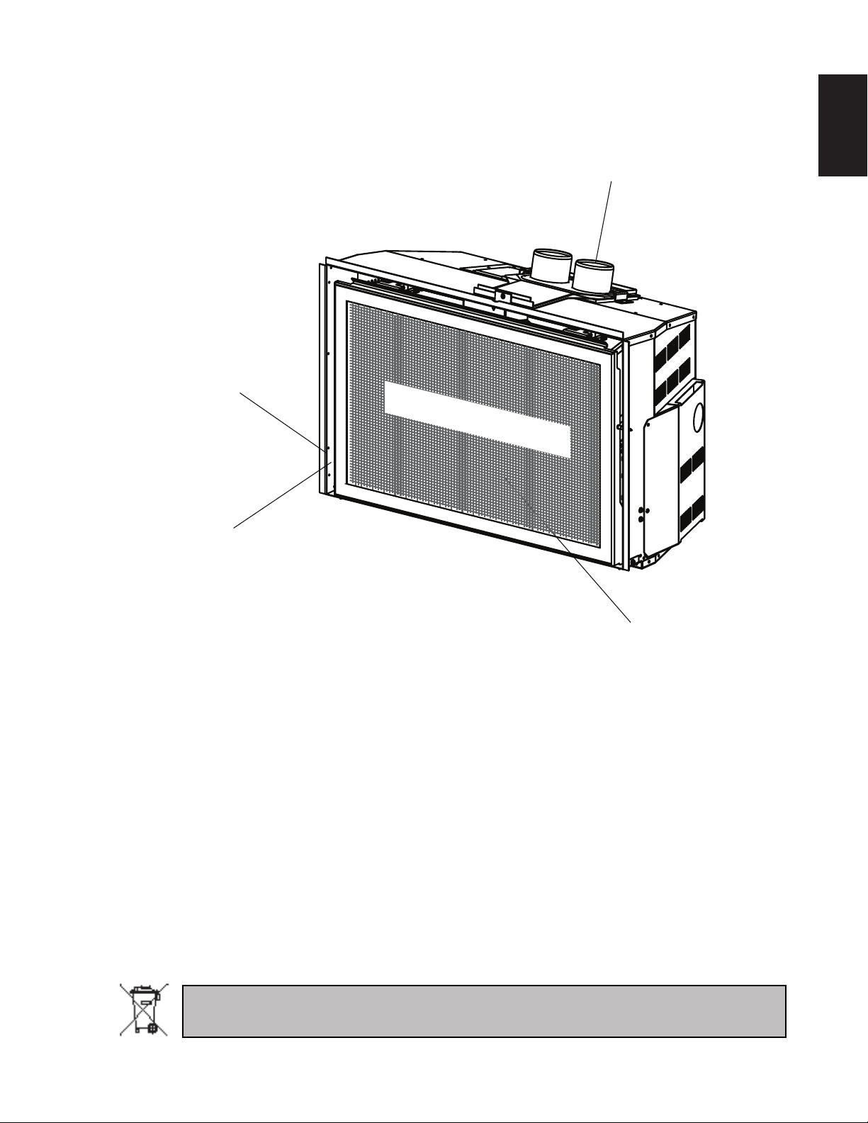
Venting, see “INSTALLATION
- CHIMNEY CONNECTION”
section.
Rating Plate, see “RATING
PLATE INFORMATION”
section.
Logs, see “FINISHING - LOG
PLACEMENT” section.
Batteries, see “BATTERY INSTALLATION” section.
Receiver, see “PROGRAMMING” section.
SAFETY BARRIER
1.0 INSTALLATION OVERVIEW
Batteries must be disposed of according to the local laws and regulations. Some batteries may be
recycled, and may be accepted for disposal at your local recycling center. Check with your municipality
for recycling instructions.

W415-1343 / A / 11.18.16
4
EN
2.0 INTRODUCTION
3.2C
!
WARNING
• THIS APPLIANCE IS HOT WHEN OPERATED AND CAN CAUSE SEVERE BURNS IF CONTACTED.
• ANY CHANGES OR ALTERATIONS TO THIS APPLIANCE OR ITS CONTROLS CAN BE DANGEROUS AND IS
PROHIBITED.
• Do not operate appliance before reading and understanding operating instructions. Failure to operate appliance
according to operating instructions could cause fi re or injury.
• Risk of fi re or asphyxiation do not operate appliance with fi xed glass removed.
• Do not connect 110 volts to the control valve.
• Risk of burns. The appliance should be turned off and cooled before servicing.
• Do not install damaged, incomplete or substitute components.
• Risk of cuts and abrasions. Wear protective gloves and safety glasses during installation. Sheet metal edges may
be sharp.
• Do not burn wood or other materials in this appliance.
• Children and adults should be alerted to the hazards of high surface temperature and should stay away to
avoid burns or clothing ignition.
• Young children should be carefully supervised when they are in the same room as the appliance.
Toddlers, young children and others may be susceptible to accidental contact burns. A physical barrier
is recommended if there are at risk individuals in the house. To restrict access to an appliance, install an
adjustable safety gate to keep toddlers, young children and other at risk individuals out of the room and
away from hot surfaces.
• Clothing or other fl ammable material should not be placed on or near the appliance.
• Due to high temperatures, the appliance should be located out of traffi c and away from furniture and
draperies.
• Ensure you have incorporated adequate safety measure to protect infants/toddlers from touching hot surfaces.
• Even after the appliance is out, the glass and/or screen will remain hot for an extended period of time.
• Check with your local hearth specialty dealer for safety screens and hearth guards to protect children from hot
surfaces. These screens and guards must be fastened to the fl oor.
• Any safety screen, guard or barrier removed for servicing the appliance, must be replaced prior to operating
the appliance.
• The appliance is a vented gas-fi red appliance. Do not burn wood or other materials in the appliance
• It is imperative that the control compartments, burners and circulating blower and its passageway in the appliance
and venting system are kept clean. The appliance and its venting system should be inspected before use and at
least annually by a qualifi ed service person. More frequent cleaning may be required due to excessive lint from
carpeting, bedding material, etc. The appliance area must be kept clear and free from combustible materials,
gasoline and other fl ammable vapors and liquids.
• Under no circumstances should this appliance be modifi ed.
• This appliance must not be connected to a chimney fl ue pipe serving a separate solid fuel burning appliance.
• Do not use this appliance if any part has been under water. Immediately call a qualifi ed service technician to
inspect the appliance and to replace any part of the control system and any gas control which has been under
water.
• Do not operate the appliance with the glass door removed, cracked or broken. Replacement of the glass should be
done by a licensed or qualifi ed service person.
• Do not strike or slam shut the appliance glass door.
• When equipped with pressure relief doors, they must be kept closed while the appliance is operating to prevent
exhaust fumes containing carbon monoxide, from entering into the home. Temperatures of the exhaust escaping
through these openings can also cause the surrounding combustible materials to overheat and catch fi re.
• Only doors / optional fronts certifi ed with the appliance are to be installed on the appliance.
• Keep the packaging material out of reach of children and dispose of the material in a safe manner. As with all
plastic bags, these are not toys and should be kept away from children and infants.
• As with any combustion appliance, we recommend having your appliance regularly inspected and serviced as well
as having a Carbon Monoxide Detector installed in the same area to defend you and your family against Carbon
Monoxide.
• Ensure clearances to combustibles are maintained when building a mantel or shelves above the appliance.
Elevated temperatures on the wall or in the air above the appliance can cause melting, discolouration or damage of
decorations, a T.V. or other electronic components.
• A barrier designed to reduce the risk of burns from the hot viewing glass is provided with this appliance and
shall be installed.
• If the barrier becomes damaged, the barrier shall be replaced with the manufacturer’s barrier for this
appliance.
• Installation and repair should be done by a qualifi ed service person. The appliance should be inspected
before use and at least annually by a professional service person. More frequent cleaning may be required
due to excessive lint from carpeting, bedding material, etc. It is imperative that control compartments,
burners and circulating air passageways of the appliance be kept clean.
W415-1343 / A / 11.18.16
5
EN
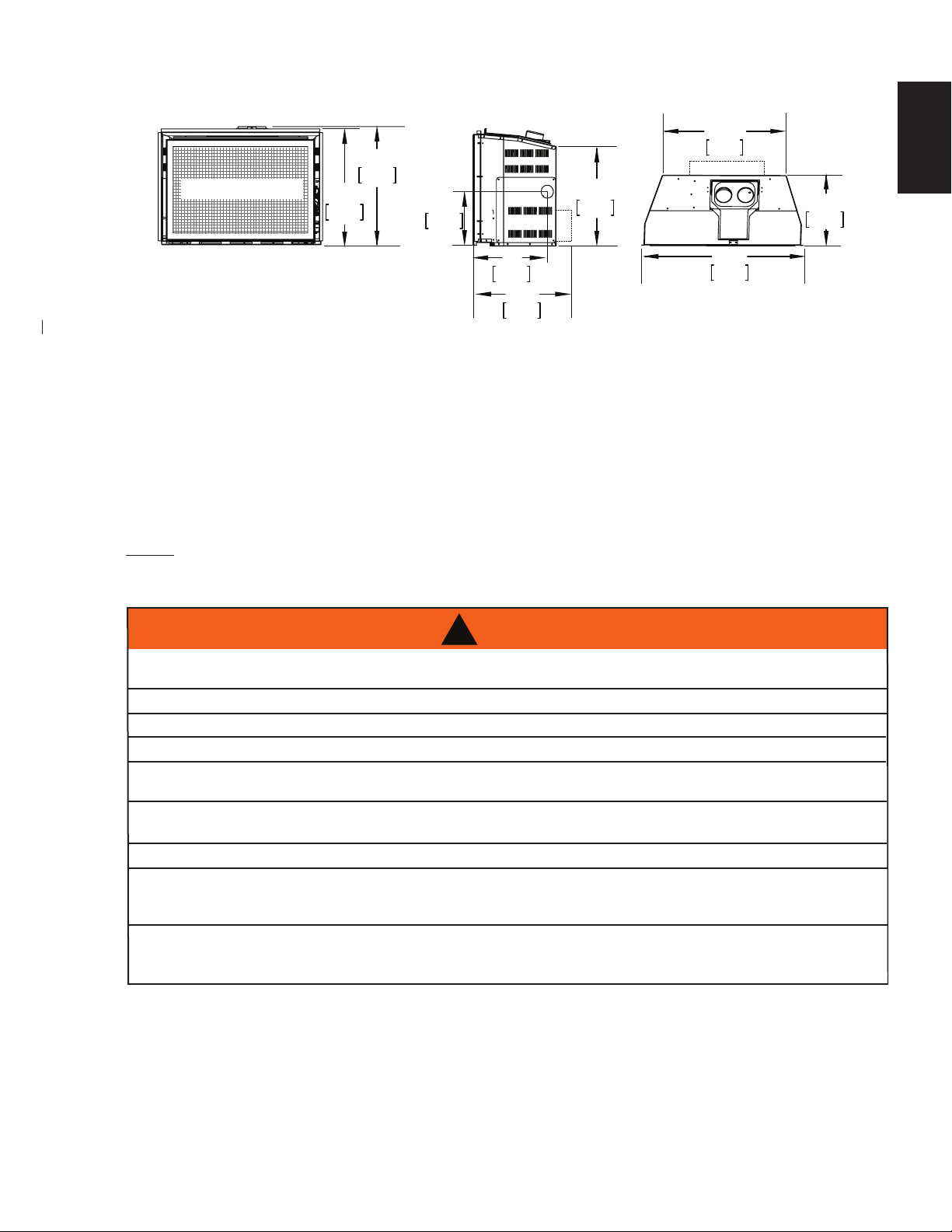
2.1 DIMENSIONS
THIS GAS APPLIANCE SHOULD BE INSTALLED AND SERVICED BY A QUALIFIED INSTALLER
to
conform with local codes. Installation practices vary from region to region and it is important to know the
specifi cs that apply to your area, for example in Massachusetts State:
• This product must be installed by a licensed plumber or gas fi tter when installed within the commonwealth
of Massachusetts.
• The appliance damper must be removed or welded in the open position prior to installation of an appliance
insert or gas log.
•
The appliance off valve must be a “T” handle gas cock.
•
The fl exible connector must not be longer than 36 inches (91.4cm).
• A Carbon Monoxide detector is required in all rooms containing gas fi red appliances.
• The appliance is not approved for installation in a bedroom or bathroom unless the unit is a direct vent
sealed combustion product.
The installation must conform with local codes or, in
absence of local codes, the National Gas and Propane
Installation Code CSA B149.1 in Canada, or the National
Fuel Gas Code, ANSI Z223.1 / NFPA 54 in the United
States. Suitable for mobile home installation if installed in
accordance with the current standard CAN/CSA Z240MH
Series, for gas equipped mobile homes, in Canada or
ANSI Z223.1 and NFPA 54 in the United States.
Some appliances have optional fans or blowers. If an optional fan or blower is installed, the junction box must
be electrically connected and grounded in accordance with local codes, use the current CSA C22.1 Canadian
Electrical Code in Canada or the ANSI/NFPA 70 National Electrical code in the United States.
ALWAYS LIGHT THE PILOT WHETHER FOR THE FIRST TIME OR IF THE GAS SUPPLY HAS RUN OUT,
WITH THE GLASS DOOR OPENED OR REMOVED.
PROVIDE ADEQUATE CLEARANCE FOR SERVICING AND OPERATING THE APPLIANCE.
PROVIDE ADEQUATE VENTILATION.
NEVER OBSTRUCT THE FRONT OPENING OF THE APPLIANCE.
OBJECTS PLACED IN FRONT OF THE APPLIANCE MUST BE KEPT A MINIMUM OF 48 INCHES
(121.9cm) FROM THE FRONT FACE OF THE APPLIANCE.
SURFACES AROUND AND ESPECIALLY ABOVE THE APPLIANCE CAN BECOME HOT. AVOID CONTACT
WHEN THE APPLIANCE IS OPERATING.
FIRE RISK. EXPLOSION HAZARD.
HIGH PRESSURE WILL DAMAGE VALVE. DISCONNECT GAS SUPPLY PIPING BEFORE PRESSURE TESTING GAS
LINE AT TEST PRESSURES ABOVE 1/2 PSIG. CLOSE THE MANUAL SHUT-OFF VALVE BEFORE PRESSURE
TESTING GAS LINE AT TEST PRESSURES EQUAL TO OR LESS THAN 1/2 PSIG (35mb).
USE ONLY WOLF STEEL APPROVED OPTIONAL ACCESSORIES AND REPLACEMENT PARTS WITH THIS APPLIANCE.
USING NON-LISTED ACCESSORIES (BLOWERS, DOORS, LOUVRES, TRIMS, GAS COMPONENTS, VENTING
COMPONENTS, ETC.) COULD RESULT IN A SAFETY HAZARD AND WILL VOID THE WARRANTY AND CERTIFICATION.
THE APPLIANCE MUST NOT BE OPERATED AT TEMPERATURES BELOW FREEZING (32°F / 0°C).
!
WARNING
This appliance must be recessed into a vented noncombustible wood-burning appliance (prefabricated or
masonry) only. The minimum appliance opening size in which the appliance is to be installed is:
HEIGHT 21
1
/
2
" (54.6cm) WIDTH 29" (73.7cm) DEPTH *13
1
/
2
" (34.3cm)
The minimum allowable chimney flue size is 7" (177.8mm) round.
*Add 4" (102mm) for optional blower.
The minimum distance, from the bottom of a combustible mantel projecting 3" (76mm) maximum from the
wall to the top of the appliance, is 14" (35.6cm) (See MINIMUM MANTEL CLEARANCES section).
NOTE: A NON-COMBUSTIBLE HEARTH MUST PROTRUDE A MINIMUM OF 12" (30.5cm) FROM THE
APPLIANCE.
2.2 MINIMUM CLEARANCE TO COMBUSTIBLES
21"
533mm
20 1/2"
521mm
12"
305mm
17 1/2"
445mm
9 1/2"
241mm
17 1/2"
445mm
29 5/8"
753mm
22 7/8"
581mm
13 1/4"
337mm
SAFETY BARRIER
2.3 GENERAL INSTRUCTIONS
*
*REQUIRED DIMENSION WITH THE OPTIONAL BLOWER KIT INSTALLED.
W415-1343 / A / 11.18.16
6
EN
2.4 GENERAL INFORMATION
4.12A
conform with local codes. Installation practices vary from region to region and it is important to know the
specifi cs that apply to your area, for example in Massachusetts State:
• This product must be installed by a licensed plumber or gas fi tter when installed within the commonwealth
of Massachusetts.
• The appliance damper must be removed or welded in the open position prior to installation of an appliance
insert or gas log.
• The appliance off valve must be a “T” handle gas cock.
• The fl exible connector must not be longer than 36 inches (91.4cm).
• A Carbon Monoxide detector is required in all rooms containing gas fi red appliances.
•
The appliance is not approved for installation in a bedroom or bathroom unless the unit is a direct vent
sealed combustion product.
The installation must conform with local codes or, in
absence of local codes, the National Gas and Propane
Installation Code CSA B149.1 in Canada, or the National
Fuel Gas Code, ANSI Z223.1 / NFPA 54 in the United
States. Suitable for mobile home installation if installed in
accordance with the current standard CAN/CSA Z240MH
Series, for gas equipped mobile homes, in Canada or
ANSI Z223.1 and NFPA 54 in the United States.
Some appliances have optional fans or blowers. If an optional fan or blower is installed, the junction box must
be electrically connected and grounded in accordance with local codes, use the current CSA C22.1 Canadian
Electrical Code in Canada or the ANSI/NFPA 70 National Electrical code in the United States.
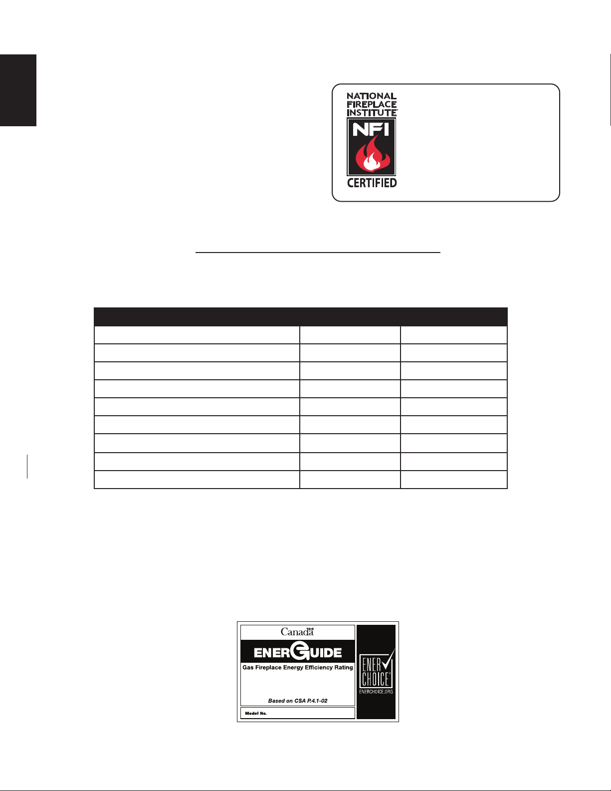
We suggest that our gas
hearth products be installed
and serviced by professionals
who are certified in the U.S.
by the National Fireplace
Institute
®
(NFI) as NFI Gas
Specialists
www.nficertified.org
FOR YOUR SATISFACTION, THIS APPLIANCE HAS BEEN TEST-FIRED TO ASSURE ITS OPERATION AND
QUALITY!
XIR3
NG P
Altitude (FT) 0-4,500 0-4,500
Max. Input (BTU/HR) 31,000 31,000
Max. Output (BTU/HR) 24,800 24,800
Efficiency (w/the fan on) 80% 80%
A.F.U.E. (maximum value) 77% 77%
Min. Inlet Gas Supply Pressure 4.5"(11mb) WC 11"(27mb) WC
Max. Inlet Gas Supply Pressure 13"(32mb) WC 13"(32mb) WC
Manifold Pressure (Under Flow Conditions) 3.5"(9mb) WC 10"(25mb) WC
When the appliance is installed at elevations above 4,500ft (1371m), and in the absence of specific
recommendations from the local authority having jurisdiction, the certified high altitude input rating shall be
reduced at the rate of 4% for each additional 1,000ft (305m). Expansion / contraction noises during heating
up and cooling down cycles are normal and to be expected.
This appliance is not approved for closet or recessed installations. It is approved for bathroom, bedroom
and bed-sitting room installations and is suitable for mobile homes. The natural gas model is suitable for
installation in a mobile home that is permanently positioned on its site and fuelled with natural gas.
A barrier designed to reduce the risk of burns from the hot viewing glass is provided with the
appliance and must be installed.
67.0%
XIR3
W415-1343 / A / 11.18.16
7
EN
2.5 RATING PLATE INFORMATION
INSTALLER: It is your responsibility to check off the appropriate box on the rating plate according to
the model, venting and gas type of the appliance.
For rating plate location, see “INSTALLATION OVERVIEW” section.
This illustration is for reference only. Refer to the rating plate on the appliance for accurate information.
NOTE: The rating plate must remain with the appliance at all times. It must not be removed.
SERIAL NUMBER/NO. DE SERIE:
XIR3/CXIR3
AVERTISSEMENT:
N'A JOUTEZ PAS A CET APPAREIL AUCUN MATERIAU DEVANT
ENTRER EN CONTACT AVEC LES FLAMMES AUTR
E QUE CELUI QUI EST FOURNI AVEC CET
APPAREIL PAR LE FABRICANT.
PRODUIT DÉCORATIF: NE PAS UTILSER COMME APPAREIL DE CHAUFFAGE.
W385-1972 / A
ROF DEIFITREC
RUOP EEIFITREC
ASU ADANAC
XIR3N XIR3PCXIR3N
CXIR3P
MODEL
C ER TIFIED
647161# ECNEREFER
CONFORMS TO / CONFORME AUX: ANSI Z21.50-2014, CERTIFIED TO / CERTIFIE CSA 2.22-2014 VENTED GAS FIREPLACE / FOYER À GAZ VENTILÉ.
WOLF STEEL LTD.
24 NAPOLEON ROAD, BARRIE. ONTARIO L4M 0G8 CANADA
ELECTRICAL RATING:
115V 1.5AMP 60HZ
THE APPLIANCE MUST BE VENTED USING THE APPROPRIATE WOLF STEEL VENT KITS. SEE
OWNER’S INSTALLATION MANUAL FOR VENTING SPECIFICS. PROPER REINSTALLATION AND
RESEALING IS NECESSARY AFTER SERVICING THE VENT-AIR INTAKE SYSTEM.
WARNING:
FOR INSTALLATION INTO A VENTED NON-COMBUSTIBLE FIREPLACE ONLY. THE
MINIMUM FIREPLACE SIZE IS: HEIGHT 20.5”, DEPTH 13.5”, WIDTH 29”. THE MINIMUM INSIDE
FLUE SIZE IS 7”. THE MINIMUM DISTANCE FROM THE BOTTOM OF A COMBUSTIBLE MANTEL
PROJECTING A MAXIMUM 3” FROM THE WALL TO THE TOP OF THE UNIT IS 14”. SEE OWNER’S
MANUAL FOR GREATER EXTENSIONS.
OPTIONAL FAN KIT - GZ550-KT, GD65.
CLASS :
115V, 1.5AMP, 60HZ
L’APPAREIL DOIT EVACUER SES GAZ EN UTILISANT L’ENSEMBLE D’EVACUATION PROPRE A WOLF STEEL.
REFERER AU MANUEL D’INSTALLATION DE PROPRIETAIRE POUR L’EVACUATION PRECISE. IL EST IMPORTANT DE
BIEN REINSTALLER ET RESCELLER L’EVENT APRES AVOIR ASSURE LE MAINTIEN DU SYSTEME DE PRISE D’AIR.
ATTENTION :
POUR INSTALLATION DANS UN FOYER VENTILE EN MACONNERIE. LES DIMENSIONS MINIMUMS
SONT: HAUTER 21.5”, PROFONDEUR 13.5”, LARGEUR 29”. LE DIAMETRE INTERIEUR MINIMUM DE CONDUIT
D’EVACUATION EST DE 7”. LA DISTANCE MINIMALE, DU BAS DU MANTEAU COMBUSTIBLE FORMANT UNE
PROJECTION MAXIMALE DE 3” DU MUR AU DESSUS DE LA GARNITURE NORMALE EST 14”. REFERER AU MANUEL
D’INSTALLATION POUR DES EXTENSIONS PLUS GRANDES.
SOUFFLERIE OPTIONELLE
GZ550-KT, GD65.
4500FT (0-1370m) ALTITUDE/ELEVATION 4500FT (0-1370m)
h/UTB 000,13 NOITATNEMILA/TUPNI h/UTB 000,13
11,000 BTU/h REDUCED INPUT/ALIMENTATION REDUITE 16,000 BTU/h
MANIFOLD PRESSURE: 3.5” WATER COLUMN
PRESSION AU COLLECTEUR: 3.5” D’UNE COLONNE D’EAU
MINIMUM SUPPLY PRESSURE: 4.5” WATER COLUMN
PRESSION D’ALIMENTATION MINIMALE: 4.5” D’UNE COLONNE D’EAU
MAXIMUM SUPPLY PRESSURE:
7.0” WATER COLUMN
PERSSION D’ALIMENTATION MAXIMALE:
7.0” D’UNE COLONNE D’EAU
MANIFOLD PRESSURE: 10” WATER COLUMN
PRESSION AU COLLECTEUR: 10” D’UNE COLONNE D’EAU
MINIMUM SUPPLY PRESSURE: 11” WATER COLUMN
PRESSION D’ALIMENTATION MINIMALE: 11” D’UNE COLONNE D’EAU
MAXIMUM SUPPLY PRESSURE: 13” WATER COLUMN
PERSSION D’ALIMENTATION MAXIMALE: 13” D’UNE COLONNE D’EAU
THIS VENTED GAS FIREPLACE IS NOT FOR USE WITH
AIR FILTERS. FOR USE WITH GLASS DOORS CERTIFIED
FOR THIS UNIT ONLY. NOT FOR USE WITH SOLID FUEL.
CE FOYER À GAZ VENTILÉS NE DOIT PAS ÊTRE UTILISÉ
CONJOINTEMENT AVEC DES FILTRES À AIR. UTILISER AVEC LES
PORTES VITRÉES HOMOLOGUÉES AVEC CETTE UNITÉ SEULE-
MENT. UN COMBUSTIBLE SOLIDE NE DOIT PAS ETRE UTILISE
AVEC CET APPAREIL.
NE PAS ALLUMER SI DES ENFANTS OU D’AUTRES INDIVIDUS À RISQUE
SONT À
PROXIMITÉ DU FOYER. FOYER À GAZ VENTILÉ HOMOLOGUÉ POUR INSTALLATION
DANS UNE CHAMBRE À COUCHER, UNE SALLE DE BAIN ET UN STUDIO. APPROPRIÉ
POUR INSTALLATION DANS UNE MAISON MOBILE SI SON INSTALLATION EST
CONFORME AUX EXIGENCES DE LA NORME CAN/CSA Z240MH SÉRIE DE MAISONS
MOBILES ÉQUIPÉES AU GAZ, EN VIGUEUR AU CANADA, OU AUX ÉTATS-UNIS, SELON
LA NORME DE SÉCURITÉ ET DE CONSTRUCTION DE MAISONS MANUFACTURÉES,
TITRE 24 CFR, SECTION 3280. DANS LE CAS OÙ CETTE NORME DES ÉTATS-UNIS
NE PEUT ÊTRE APPLIQUÉE, SE RÉFÉRER À LA NORME RELATIVE AU CRITÈRE DE
MESURES DE SÉCURITÉ CONTRE L'INCENDIE POUR LES INSTALLATIONS DANS LES
MAISONS MANUFACTURÉES, LES SITES ET LES COMMUNAUTÉS, ANSI/NFPA 501A.
POUR UNE UTILISER AVEC BARRIÈRE W565-0133. SUIVEZ LES INSTRUCTIONS
D'INSTALLATION SE TROUVENT DANS LE MANUEL D'INSTALLATION
.
DO NOT TURN ON IF CHILDREN OR OTHER AT RISK INDIVIDUALS
ARE NEAR THE FIREPLACE. DIRECT VENT GAS FIREPLACE.
SUITABLE FOR BEDROOM, BATHROOM AND BED-SITTING
ROOM INSTALLATION. SUITABLE FOR MOBILE HOME INSTALLATION
IF INSTALLED IN ACCORDANCE WITH THE CURRENT STANDARD
CAN/CSA Z240MH SERIES GAS EQUIPPED MOBILE HOMES, IN
CANADA OR IN THE UNITED STATES THE MANUFACTURED HOME
CONTRUCTION AND SAFETY STANDARD, TITLE 24 CFR, PART 3280.
WHEN THIS US STANDARD IS NOT APPLICABLE USE THE
STANDARD FOR FIRE SAFETY CRITERIA FOR MANUFACTURED
HOME INSTALLATIONS, SITES AND COMMUNITIES, ANSI / NFPA
501A
.
FOR USE WITH BARRIER W565-0133. FOLLOW THE INSTALLATION
INSTRUCTIONS LOCATED IN THE INSTALLATION MANUA
L.
WARNING: DO NOT ADD ANY MATERIAL TO THE APPLIANCE THAT WILL COME IN
CONTACT WITH THE FLAMES, OTHER THAN THAT SUPPLIED BY THE MANUFACTURER
WITH THE APPLIANCE.
DECORATIVE PRODUCT: NOT FOR USE AS A HEATING APPLIANCE
P.4: 67%
P.4: 67%
NATURAL GAS / GAZ MODEL
PROPANE MODEL
SAMPLE
W415-1343 / A / 11.18.16
8
EN
3.0 INSTALLATION
3.1 LEVELLING THE APPLIANCE
68.4B
Clean out ashes from the inside of the wood-burning appliance. Make sure that the chimney and wood-burning
appliance are in a clean and sound condition and constructed of non-combustible materials. If necessary have
any repair work done by a qualifi ed person before installing the insert. Remove the existing appliance damper
or lock into an open position.
Using screws, attach the appliance warning tag
to the inside of the fi rebox of the appliance into
which the insert is being installed.
The sheet-metal parts of the appliance, in which
the gas appliance insert is to be installed, must
not be cut.
If the wood-burning factory-built appliance has
no gas access hole(s) provided, an access hole of 1½ inch (38.1mm) or less may be drilled through the lower
sides or bottom of the appliance in a proper workman like manner. This access hole must be plugged with non-
combustible insulation after the gas supply line has been installed.
Ensure that existing chimney cleanouts fi t properly.
The refractory, glass doors, screen rails, screen mesh and log grates may be removed from the existing
appliance before installing the gas appliance insert.
Smoke shelves, shields and baffl es may be removed if attached by mechanical fasteners.
The ventilation openings in the existing appliance may be obstructed by the backer plates, aluminium trim etc.
but these parts are not to be applied so as to have an airtight seal.
!
WARNING
RISK OF FIRE, MAINTAIN SPECIFIED AIR SPACE CLEARANCES TO VENT PIPE AND APPLIANCE.
W385-0199_B
WARNING: THIS FIREPLACE HAS BEEN CONVERTED FOR USE WITH A GAS FIREPLACE
INSERT ONLY AND CANNOT BE USED FOR BURNING WOOD OR SOLID FUELS UNLESS ALL ORIGINAL
PARTS HAVE BEEN REPLACED AND THE FIREPLACE IS RE-APPROVED BY THE AUTHORITY HAVING
JURISDICTION.
ATTENTION: CE FOYER A ETE CONVERTI AFIN D’ETRE UTILISE SEULEMENT
COMME FOYER ENCASTRE AU GAZ ET NE PEUT ETRE UTILSE POUR BRULER DU BOIS OU
TOUT AUTRE COMBUSTIBLE SOLIDE, SANS QUE TOUTES LES PIECES ORIGINALES AIENT
ETE REMPLACEES ET QUE LE FOYER SOIT APPROUVE DE NOUVEAU PAR LES AUTORITES
AYANT JURIDICTION.
ADVERTENCIA: ESTA CHIMENEA SE REMODELÓ PARA USARSE SOLO CON UNA
INSERCIÓN DE CHIMENEA A GAS Y NO PUEDE USARSE PARA QUEMAR MADERA NI COMBUSTIBLES
SÓLIDOS, A MENOS QUE SE HAYAN REEMPLAZADO TODAS LAS PIEZAS ORIGINALES, Y LA AUTORI-
DAD JURISDICCIONAL LA HAYA VUELTO A APROBAR.
Move the appliance close to its fi nal position. This appliance is equipped with levelling screws located on the
base. Level using the levelling screws. Levelling the appliance will eliminate rocking or excessive noise when
the fan is in operation. Once the appliance is level, move it partially into place to allow for all connections to be
made. It is not practical to level the appliance once it has been installed. Determine the required depth prior to
installing the appliance and adjust the levelling screws accordingly.
67.2
W415-1343 / A / 11.18.16
9
EN
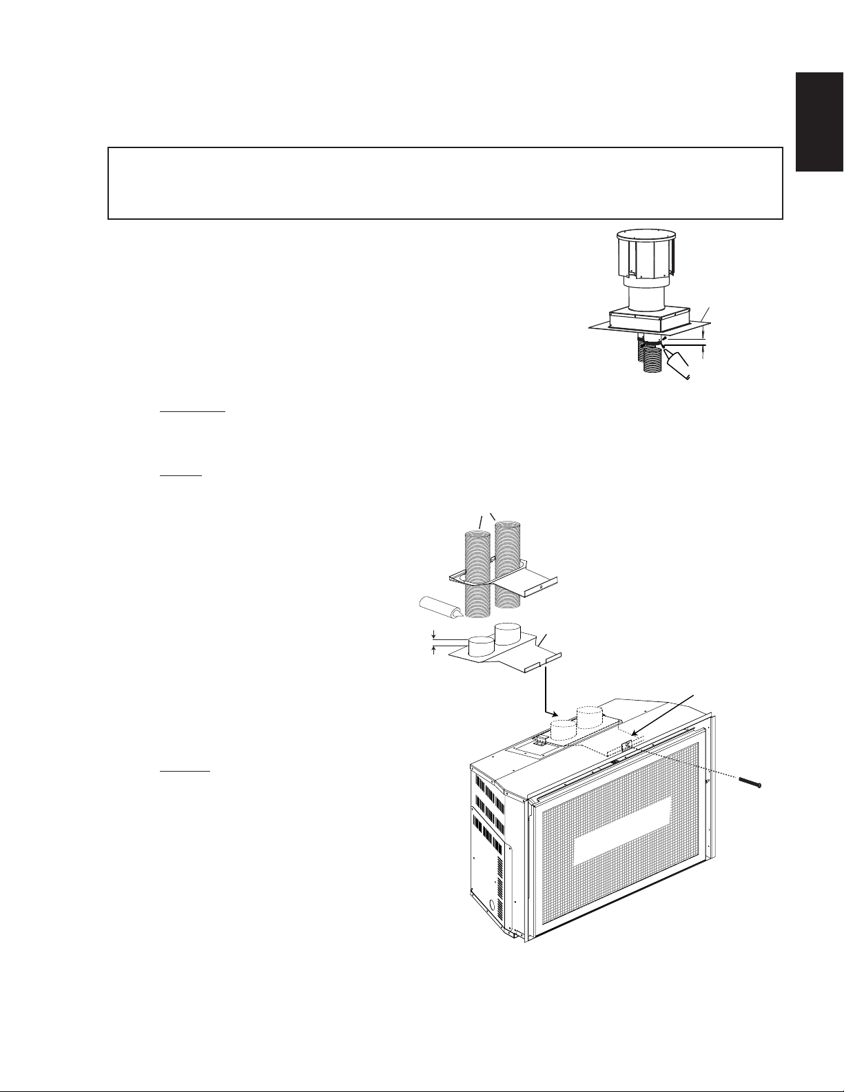
While the liners must be continuous from the appliance to the chimney cap,
to achieve the needed length, they may be coupled, using an approved
coupler.
We recommend that exhaust vents that pass through unheated spaces,
such as tall exterior chimneys, be wrapped in a protective sleeve to minimize
condensation and reverse flow symptoms. See "TROUBLESHOOTING"
section for details.
This appliance is approved for use with a 3" (76mm) exhaust and air intake.
A. OUTSIDE: Slip the one end of a liner a minimum of 2"( 51mm)
over the sleeve of the air terminal. Secure using 3 screws. Then seal the joint and screw heads with
high temperature sealant. Repeat with the other liner.
NOTE: We recommend that the other end of the exhaust liner be marked to eliminate the
exhaust liner being connected
to the intake collar at the
appliance.
B. Gently stretch the liners to the
required lengths and insert
into the chimney. Trim and fit
the flashing plate to suit the
chimney termination. Place the
air terminal onto the top of the
chimney. Make weather tight
by sealing with caulking (not
supplied). Fasten to the chimney
with screws and plugs (not
supplied).
C. INSIDE: Remove the securing
screw from the front of the vent
mounting plate. Pull the vent
mounting plate only, back into
the track, to the front stop. Start
the slider back into position. Re-
secure the screw. The appliance
may now be pushed into its
final position inside the wood
burning appliance, and the screw
tightened until the slider has
been pulled tight to the front stop.
D. Route the flex liners through the slider. Attach and secure the liners to the vent mounting plate using
the same procedure as before, ensuring that the marked exhaust liner is attached to the exhaust
collar.
FLASHING
PLATE
2” (50.8mm)
OVERLAP
SEALANT
HI-TEMP
INTAKE
EXHAUST
SECURING
SCREW
SLIDER
MOUNTING
PLATE
HIGH TEMP
SEALANT
2” (50.8mm)
OVERLAP
3” (76.2mm)
LINERS
EXHAUST
INTAKE
VENT MOUNT
ASSEMBLY
SAFETY BARRIER
3.2 CHIMNEY CONNECTION
Chimney installation must conform to both national and local code requirements. The chimney must be lined
with one 3" (76mm) diameter liner for intake and one 3" (76mm) diameter liner for exhaust. The minimum and
maximum vent lengths are 10' (3m) and 35' (10m) respectively. Recommended kits come in 3 lengths:
2-3" (50.8mm-76.2mm) DOUBLE PLY ALUMINUM LINER-INLET AND EXHAUST:
GDI-320KT VENT KIT 20FT
GDI-325KT VENT KIT 25 FT
GDI-335KT VENT KIT 35 FT
W415-1343 / A / 11.18.16
10
EN
3.3 GAS INSTALLATION
30.1A
Installation and servicing to be done by a qualifi ed installer.
•
Move the appliance into position and secure.
•
If equipped with a fl ex connector the appliance is designed to accept a 1/2” (13mm) gas supply.
Without the connector it is designed to accept a 3/8” (9.5mm) gas supply. The appliance is equipped
with a manual shut off valve to turn off the gas supply to the appliance.
•
Connect the gas supply in accordance to local codes. In the absence of local codes, install to the
current CAN/CSA-B149.1 Installation Code in Canada or to the current National Fuel Gas Code, ANSI
Z223.1 / NFPA 54 in the United States.
•
When fl exing any gas line, support the gas valve so that the lines are not bent or kinked.
• The gas line fl ex-connector should be installed to provide suffi cient movement for shifting the burner
assembly on its side to aid with servicing components.
•
Check for gas leaks by brushing on a soap and water solution. Do not use open fl ame.
!
WARNING
RISK OF FIRE, EXPLOSION OR ASPHYXIATION. ENSURE THERE ARE NO IGNITION SOURCES SUCH AS
SPARKS OR OPEN FLAMES.
SUPPORT GAS CONTROL WHEN ATTACHING GAS SUPPLY PIPE TO PREVENT DAMAGING GAS LINE.
ALWAYS LIGHT THE PILOT WHETHER FOR THE FIRST TIME OR IF THE GAS SUPPLY HAS RUN OUT
WITH THE GLASS DOOR OPENED OR REMOVED. PURGING OF THE GAS SUPPLY LINE SHOULD BE
PERFORMED BY A QUALIFIED SERVICE TECHNICIAN. ASSURE THAT A CONTINUOUS GAS FLOW IS AT
THE BURNER BEFORE CLOSING THE DOOR. ENSURE ADEQUATE VENTILATION. FOR GAS AND
ELECTRICAL LOCATIONS, SEE “DIMENSIONS” SECTION.
ALL GAS CONNECTIONS MUST BE CONTAINED WITHIN THE APPLIANCE WHEN COMPLETE.
HIGH PRESSURE WILL DAMAGE VALVE. DISCONNECT GAS SUPPLY PIPING BEFORE TESTING GAS
LINE AT TEST PRESSURES ABOVE 1/2 PSIG.
VALVE SETTINGS HAVE BEEN FACTORY SET, DO NOT CHANGE.
W415-1343 / A / 11.18.16
11
EN
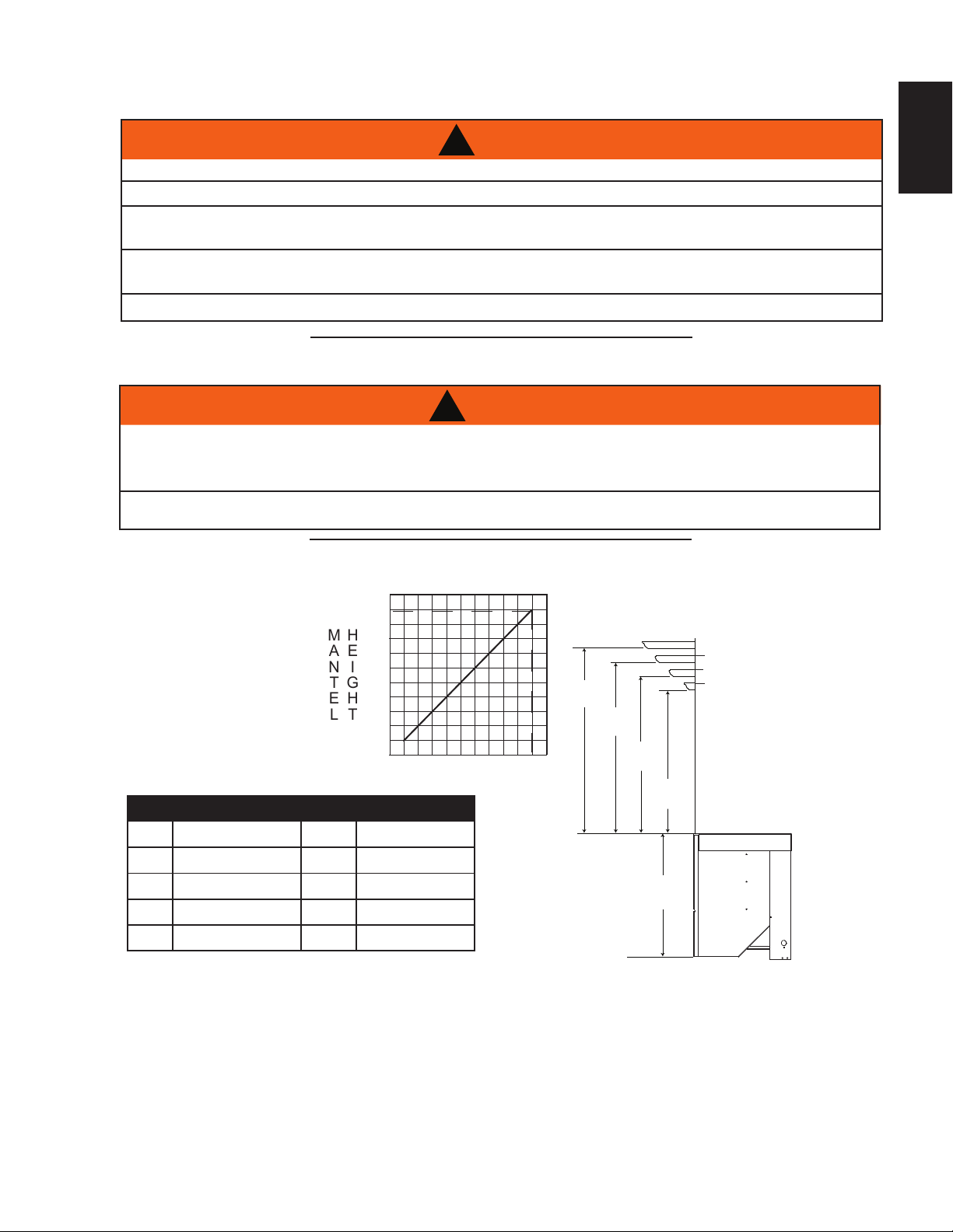
Combustible mantel clearance can vary according to the mantel depth. Use the graph to help evaluate the
clearance needed. These same requirements apply to any combustibles protruding on either side of the
appliance.
H
D
F
G
MANTEL DEPTH
0” (mm)
H
E
I
G
H
T
M
A
N
T
E
L
E
C
B
A
!
WARNING
RISK OF FIRE, MAINTAIN ALL SPECIFIED AIR SPACE CLEARANCES TO COMBUSTIBLES. FAILURE
TO COMPLY WITH THESE INSTRUCTIONS MAY CAUSE A FIRE OR CAUSE THE APPLIANCE TO
OVERHEAT. ENSURE ALL CLEARANCES (I.E. BACK, SIDE, TOP, VENT, MANTEL, FRONT, ETC.) ARE
CLEARLY MAINTAINED.
WHEN USING PAINT OR LACQUER TO FINISH THE MANTEL, THE PAINT OR LACQUER MUST BE
HEAT RESISTANT TO PREVENT DISCOLOURATION.
73.1
14”
(35.6cm)
17”
(43.2cm)
16”
(40.6cm)
15”
(38.1cm)
6”(152.4mm)
MANTEL
5”(127mm)
3” (76.2mm)
4”(101.6mm)
20
1
/
2
”
(52.1cm)
4.0 FINISHING
!
WARNING
RISK OF FIRE!
NEVER OBSTRUCT THE FRONT OPENING OF THE APPLIANCE.
IF FINISHING THE FRONT OF THE APPLIANCE, IT MUST BE FINISHED WITH ANY NON-
COMBUSTIBLE MATERIAL SUCH AS BRICK, MARBLE, GRANITE, ETC.
DO NOT STRIKE, SLAM OR SCRATCH GLASS. DO NOT OPERATE APPLIANCE WITH GLASS
REMOVED, CRACKED, BROKEN OR SCRATCHED.
FACING AND/OR FINISHING MATERIAL MUST NEVER OVERHANG INTO THE APPLIANCE OPENING.
72.1B
MANTEL DIMENSIONS
Ref Height Ref Depth
A
17" (43.2cm)
E
6" (152mm)
B
16" (40.6cm)
F
5" (127mm)
C
15" (38.1cm)
G
4" (102mm)
D
14” (35.6cm)
H
3" (76mm)
4.1 MINIMUM COMBUSTIBLE MANTEL CLEARANCES
W415-1343 / A / 11.18.16
12
EN
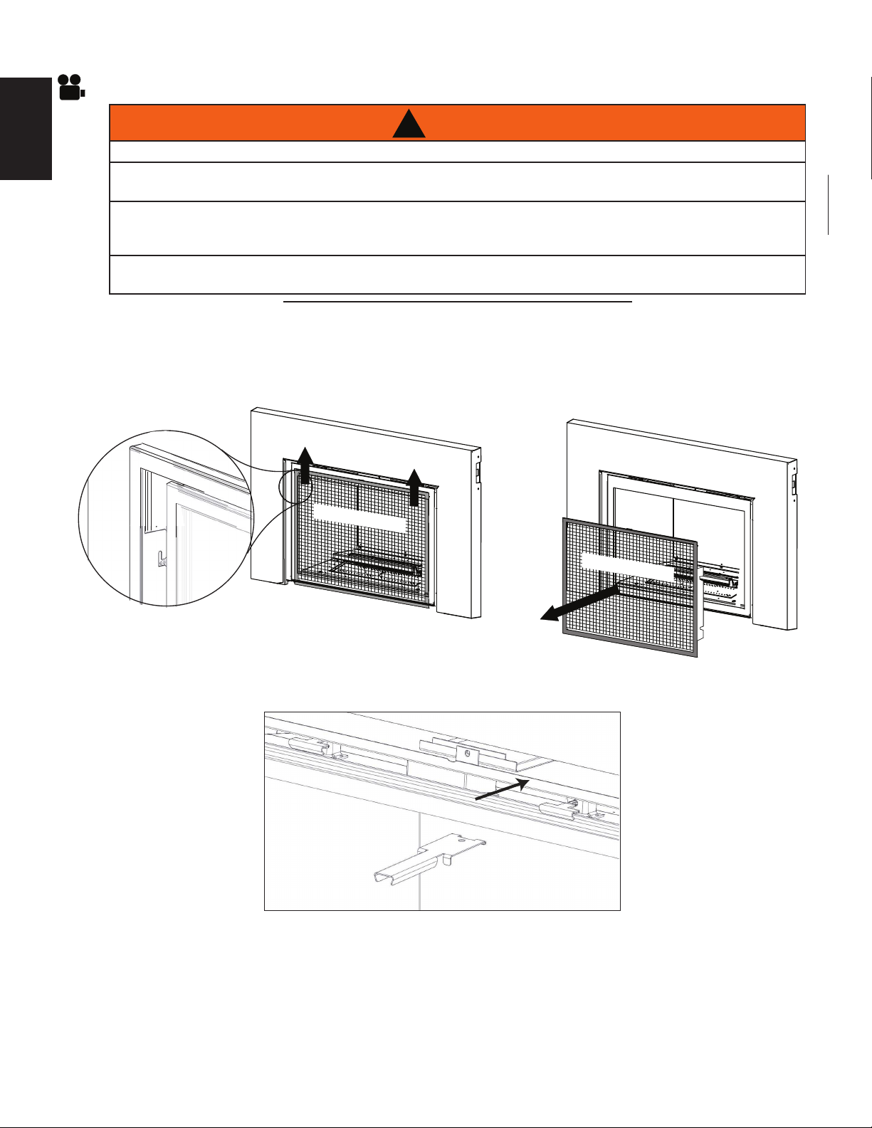
4.2 SAFETY SCREEN & DOOR REMOVAL / INSTALLATION
!
WARNING
GLASS MAY BE HOT, DO NOT TOUCH GLASS UNTIL COOLED.
IF EQUIPPED WITH DOOR LATCHES THAT ARE PART OF A SAFETY RELIEF SYSTEM, THEY MUST BE
PROPERLY ENGAGED. DO NOT OPERATE THE APPLIANCE WITH LATCHES DISENGAGED.
FACING AND/OR FINISHING MATERIALS MUST NOT INTERFERE WITH AIR FLOW THROUGH AIR
OPENINGS, LOUVRE OPENINGS, OPERATION OF LOUVRES OR DOORS OR ACCESS FOR
SERVICE. OBSERVE ALL CLEARANCES WHEN APPLYING COMBUSTIBLE MATERIALS.
BEFORE DOOR IS REMOVED TURN THE APPLIANCE OFF AND WAIT UNTIL APPLIANCE IS COOL TO
THE TOUCH. DOORS ARE HEAVY AND FRAGILE SO HANDLE WITH CARE.
75.1A
A barrier designed to reduce the risk of burns from the hot viewing glass is provided with the
appliance and shall be installed.
Before the glass door can be removed, the safety screen must be removed. Lift the safety screen off the 4
side pins and remove from the appliance.
The optional front must be removed to allow the door to be opened or closed. Release the top left and right
door latches, located at the top of the door. Tilt forward and lift from slots.
Reverse these steps to re-install the safety screen and door. Ensure safety screen is installed correctly.
SAFETY SCREEN
SAFETY SCREEN
W415-1343 / A / 11.18.16
13
EN
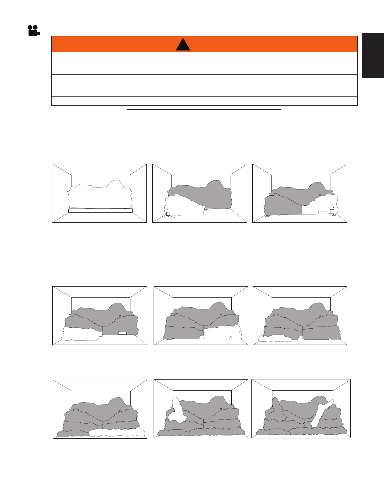
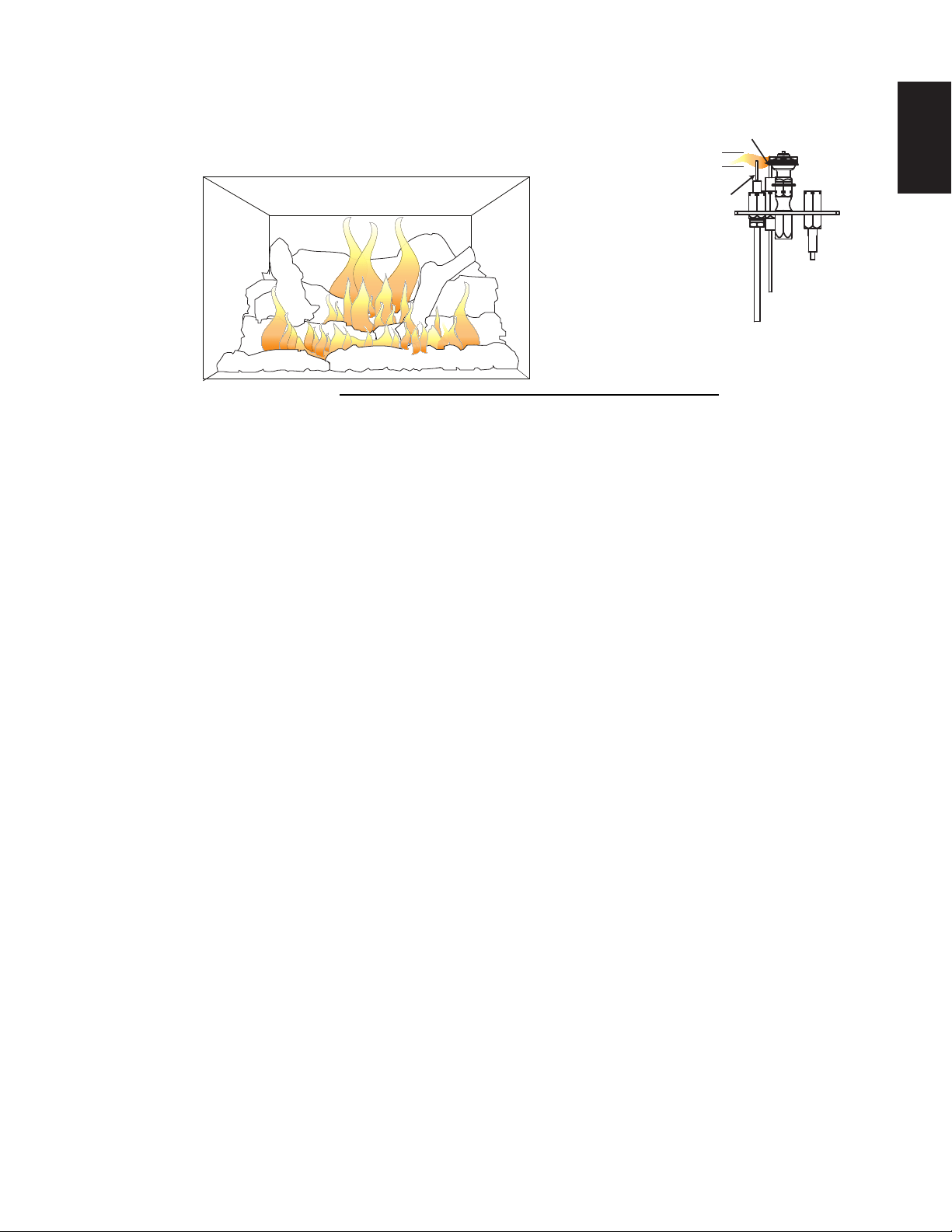
4.3 LOG PLACEMENT
!
WARNING
FAILURE TO POSITION THE LOGS IN ACCORDANCE WITH THESE DIAGRAMS OR FAILURE TO USE
ONLY LOGS SPECIFICALLY APPROVED WITH THIS APPLIANCE MAY RESULT IN PROPERTY
DAMAGE OR PERSONAL INJURY.
LOGS MUST BE PLACED IN THEIR EXACT LOCATION IN THE APPLIANCE. DO NOT MODIFY THE
PROPER LOG POSITIONS, SINCE APPLIANCE MAY NOT FUNCTION PROPERLY AND DELAYED
IGNITION MAY OCCUR.
THE LOGS ARE FRAGILE AND SHOULD BE HANDLED WITH CARE.
76.1A
PHAZER
TM
logs and glowing embers exclusive to Napoleon, provide a unique and realistic glowing effect that
is different in every installation. Take the time to carefully position the glowing embers for a maximum glowing
effect.
Log colours may vary. During the initial use of the appliance, the colours will become more uniform as colour
pigments burn in during the heat activated curing process.
LOG SUPPORT
PIN
G. Position the right charcoal strip
in front of the right front log, lining
up the 2 holes in the bottom with
the 2 front right studs.
H. Position a pin into the left side
hole of the left middle log, move
the left crossover log into position,
lining up the top hole with the pin.
C. Insert the right middle log end
onto the left log pin using the right
log support in front of the right
middle log to hold log in place.
Adjust the log supports tight to
these logs to hold them in an
upright position and ensure they are
tight to the burner.
F. Position the left charcoal strip in
front of the left front log, lining up
the 2 holes in the bottom with the
2 front left studs.
A. Place the rear log into position
lining up the holes in the bottom with
the studs located at the rear of the
firebox. Ensure it is tight to the burner.
B. Insert a pin (supplied) into the
right end of the left middle log
using the left log support in front
of the left middle log to hold log in
place.
E. Place the right front log into
position, lining up the 2 holes in the
bottom with the studs located on
the right side of the burner.
D. Place the left front log into
position, lining up the 2 holes in the
bottom with the studs located on
the left side of the burner.
I. Position a pin into the right side
hole of the right middle log, move
the right crossover log into position,
lining up the top hole with the pin.
NOTE: Log support brackets are supplied in the manual baggie.
W415-1343 / A / 11.18.16
14
EN
Tear the embers into pieces and place along the front row of ports covering all of the burner area in front of
the small logs. Care should be taken to shred the embers into thin, small irregular pieces as only the exposed
edges of the fibre hairs will glow. The ember material will only glow when exposed to direct flame;
however, care should be taken to not block the burner ports.
Blocked burner ports can cause an incorrect flame pattern, carbon deposits and delayed ignition. PHAZER
TM
logs glow when exposed to direct flame. Use only certified "glowing embers" and PHAZER
TM
logs available
from your authorized dealer / distributor.
97.1A
Remove the backing of the logo supplied and place on the glass viewing
door, as indicated.
½"
(12.7mm)
LOGO
½"
(12.7mm)
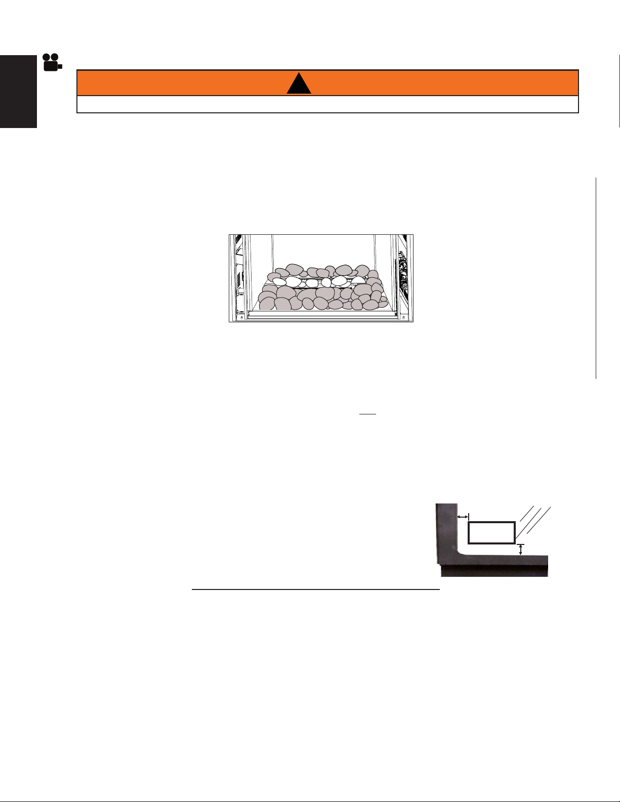
Before beginning with the installation, remove the door and all burner media from the appliance including logs
and charcoal strips. Retain the glowing embers.
A. Randomly place the rocks onto the media tray, around, but not on the burner ports or pilot area.
B. Rocks can be carefully stacked. You must ensure that none would fall onto the burner or pilot
while in operation.
C. Turn on gas and electrical supply.
D. Reinstall the glowing embers over the burner.
E. Reinstall the door.
!
WARNING
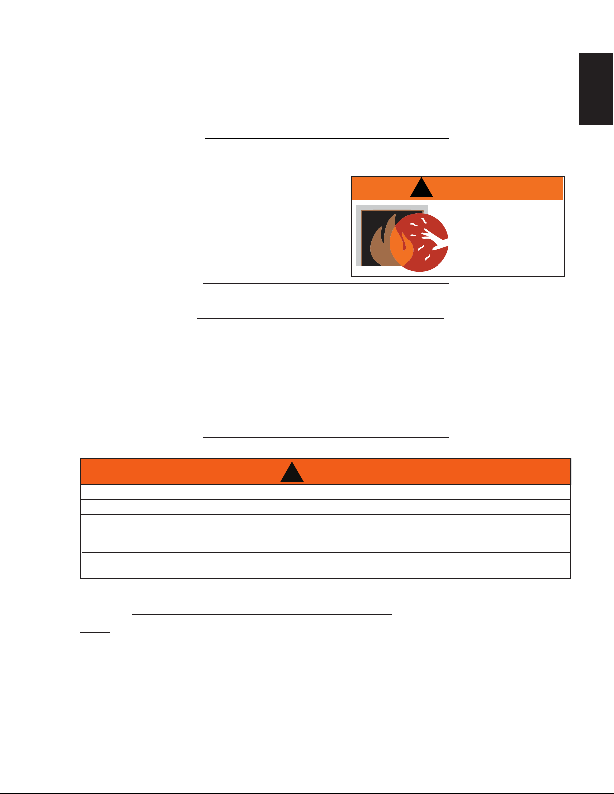
REAL ROCKS MUST NOT BE USED IN THIS APPLIANCE. HEAT WILL CAUSE THEM TO EXPLODE
4.4 OPTIONAL ROCK PLACEMENT
4.5 GLOWING EMBERS
4.6 LOGO PLACEMENT
W415-1343 / A / 11.18.16
15
EN
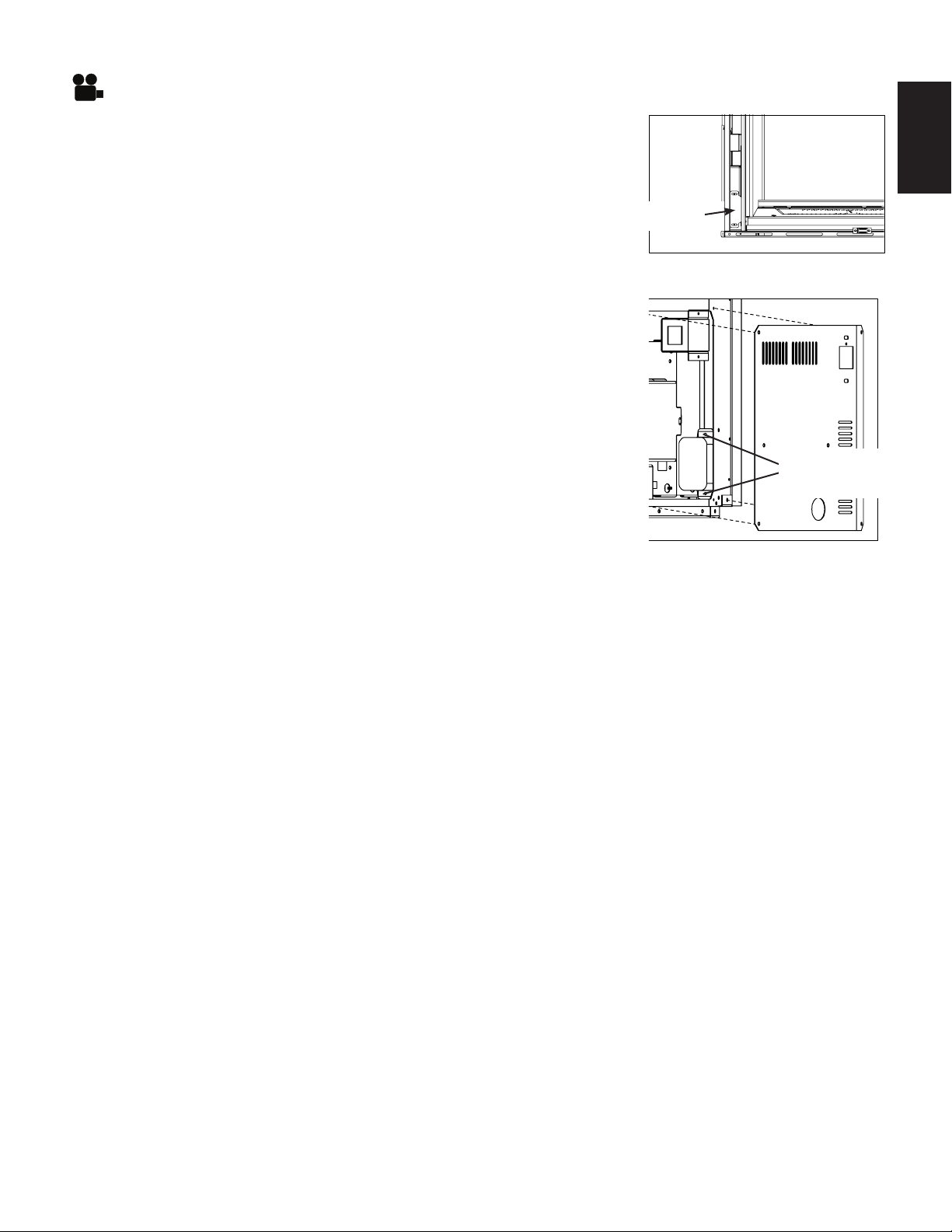
4 "AA" batteries must be installed into the receiver before operation is
possible in the XIR3. The receiver is located in the bottom left corner of
the appliance.
If receiver removal is necessary, remove the left access panel from the front
of the appliance. Remove the 2 screws holding the receiver in place. Pull
the receiver through the access hole and replace.
RECEIVER
RECEIVER PLATE
SCREWS
4.7 BATTERY INSTALLATION
W415-1343 / A / 11.18.16
16
EN
!
WARNING
DO NOT USE THIS APPLIANCE IF ANY PART HAS BEEN UNDER WATER. CALL A QUALIFIED
SERVICE TECHNICIAN IMMEDIATELY TO HAVE THE APPLIANCE INSPECTED FOR DAMAGE TO THE
ELECTRICAL CIRCUIT.
RISK OF ELECTRICAL SHOCK OR EXPLOSION. DO NOT WIRE 110V TO THE VALVE OR TO THE
APPLIANCE WALL SWITCH. INCORRECT WIRING WILL DAMAGE CONTROLS.
ALL WIRING SHOULD BE DONE BY A QUALIFIED ELECTRICIAN AND SHALL BE IN COMPLIANCE
WITH LOCAL CODES. IN THE ABSENCE OF LOCAL CODES, USE THE CURRENT CSA22.1 CANADIAN
ELECTRIC CODE IN CANADA OR THE CURRENT NATIONAL ELECTRIC CODE ANSI/NFPA NO. 70 IN
THE UNITED STATES.
ALWAYS LIGHT THE PILOT WHETHER FOR THE FIRST TIME OR IF THE GAS SUPPLY HAS RUN OUT,
WITH THE GLASS DOOR OPENED OR REMOVED.
69.2_2
5.0 ELECTRICAL INFORMATION
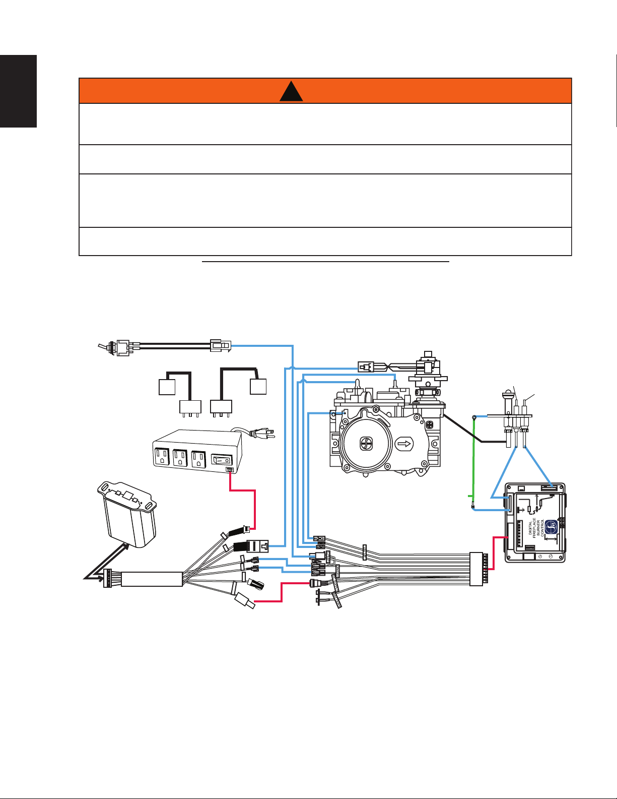
5.1 WIRING DIAGRAM
Wire Harness Assembly
IPI Board
Pilot
Ground
Wire
EI
Pilot
Spark Electrode
Flame
Sensor
Valve
Electronic Modulation
120V OUT
FAN
AUX OUT
COM
POWER
ACS/IPI Switch
(OPTIONAL)
Receiver
Wire Harness
Control Module
Night Lights
Fan
(OPTIONAL)
Wire
Harness
Plug
This appliance comes equipped with a battery back-up. If this back-up is used, install 4 AA batteries (not
supplied) into the receiver.
W415-1343 / A / 11.18.16
17
EN
6.0 OPERATION
When lit for the first time, the appliance will emit a slight odour for a few hours. This is a normal temporary
condition caused by the "burn-in" of internal paints and lubricants used in the manufacturing process and
will not occur again. Simply open a window to sufficiently ventilate the room. After extended periods of non-
operation such as following a vacation or a warm weather season, the appliance may emit a slight odour for
a few hours. This is caused by dust particles in the heat exchanger burning off. Open a window to sufficiently
ventilate the room.
IF YOU DO NOT FOLLOW THESE INSTRUCTIONS EXACTLY, A FIRE OR EXPLOSION MAY RESULT
CAUSING PROPERTY DAMAGE, PERSONAL INJURY OR LOSS OF LIFE.
ALWAYS LIGHT THE PILOT WHETHER FOR THE FIRST TIME OR IF THE GAS SUPPLY HAS RUN OUT WITH
THE GLASS DOOR OPENED OR REMOVED.
!
WARNING
6.1 OPERATING AND LIGHTING INSTRUCTIONS
WARNING:
DO NOT TURN ON IF CHILDREN OR OTHER AT RISK
INDIVIDUALS ARE NEAR THE APPLIANCE. IF YOU DO NOT FOLLOW THESE
INSTRUCTIONS EXACTLY, A FIRE OR EXPLOSION MAY RESULT CAUSING
PROPERTY DAMAGE, PERSONAL INJURY OR LOSS OF LIFE.
INITIAL LIGHTING OF THE PILOT AND MAIN BURNERS MUST BE DONE
WITH THE GLASS DOOR OFF.
DO NOT CONNECT VALVE OR WALL SWITCH TO ELECTRICITY. SEE
INSTALLATION INSTRUCTIONS.
A. THIS APPLIANCE IS EQUIPPED WITH AN IGNITION DEVICE WHICH AUTOMATICALLY
LIGHTS THE PILOT. DO NOT TRY TO LIGHT BY HAND.
B. BEFORE OPERATING, SMELL ALL AROUND THE APPLIANCE AREA FOR GAS AND NEXT TO
THE FLOOR BECAUSE SOME GAS IS HEAVIER THAN AIR AND WILL SETTLE ON THE
FLOOR.
WHAT TO DO IF YOU SMELL GAS:
• TURN OFF ALL GAS TO THE APPLIANCE.
• OPEN WINDOWS.
• DO NOT TRY TO LIGHT ANY APPLIANCE.
• DO NOT TOUCH ANY ELECTRICAL SWITCH; DO NOT USE ANY PHONE IN YOUR
BUILDING.
• IMMEDIATELY CALL YOUR GAS SUPPLIER FROM A NEIGHBOUR’S PHONE. FOLLOW THE
GAS SUPPLIER’S INSTRUCTIONS.
• IF YOU CANNOT REACH YOUR GAS SUPPLIER, CALL THE FIRE DEPARTMENT.
C. DO NOT TRY TO REPAIR ANY PART OF THIS ASSEMBLY. CALL A QUALIFIED SERVICE
TECHNICIAN. FORCE OR ATTEMPTED REPAIR MAY RESULT IN A FIRE OR EXPLOSION.
D. DO NOT USE THIS APPLIANCE IF ANY PART HAS BEEN UNDER WATER. IMMEDIATELY
CALL A QUALIFIED SERVICE TECHNICIAN TO INSPECT THE APPLIANCE AND REPLACE
ANY PART OF THE CONTROL SYSTEM AND ANY GAS CONTROL WHICH HAS BEEN UNDER
WATER.
ATTENTION:
NE PAS ALLUMER SI DES ENFANTS OU D’AUTRES
INDIVIDUS À RISQUE SONT À PROXIMITÉ DU FOYER. QUICONQUE NE
RESPECTE PAS À LA LETTRE LES INSTRUCTIONS DANS LA PRÉSENTE
NOTICE, RISQUE DE DÉCLENCHER UN INCENDIE OU UN EXPLOSION
ENTRAÎNANT DES DOMMAGES, DES BLESSURES OU LA MORT.
L’ALLUMAGE INITIAL DE LA VEILLEUSE ET DU BRÛLEUR PRINCIPAL
DOIT SE FAIRE AVEC LA PORTE VITRÉE ENLEVÉE.
NE RACCORDEZ PAS LA SOUPAPE OU L’INTERRUPTEUR MURAL À
L’ÉLECTRICITÉ. CONSULTEZ LES INSTRUCTIONS D’INSTALLATION.
A. CET APPAREIL EST MUNI D’UN DISPOSITIF D’ALLUMAGE QUI ALLUME
AUTOMATIQUEMENT LA VEILLEUSE. NE TENTEZ PAS D’ALLUMER LA VEILLEUSE
MANUELLEMENT.
B. AVANT DE FAIRE FONCTIONNER, RENIFLEZ TOUT AUTOUR DE L’APPAREIL POUR
DÉCELER UN ODEUR DE GAZ. RENIFLEZ PRÈS DU PLANCHER, CAR CERTAINS GAZ
SONT PLUS LOURDS QUE L’AIR ET PEUVENT S’ACCUMULER AU NIVEAU DU SOL.
QUE FAIRE SI VOUS DÉTECTEZ UNE ODEUR DE GAZ:
• COUPEZ L’ALIMENTATION DE GAZ PRINCIPALE.
• OUVREZ LES FENÊTRES.
• NE PAS TENTER D’ALLUMER D’APPAREIL.
• NE TOUCHEZ À AUCUN INTERRUPTEUR; NE PAS VOUS SERVIR DES TÉLÉPHONES SE
TROUVANT DANS LE BÂTIMENT.
• APPELEZ IMMÉDIATEMENT VOTRE FOURNISSEUR DE GAZ DEPUIS UN VOISIN.
SUIVEZ LES INSTRUCTIONS DU FOURNISSEUR.
• SI VOUS NE POUVEZ REJOINDRE LE FOURNISSEUR APPELEZ LE SERVICE DES
INCENDIES.
C. N’ESSAYEZ PAS DE RÉPARER AUCUNE PIÈCE DE CET ASSEMBLAGE. APPELEZ UN
TECHNICIEN QUALIFIÉ. FORCER OU TENTER DE RÉPARER L’ASSEMBLAGE POURRAIT
CAUSER UN FEU OU UNE EXPLOSION.
D. N’UTILISEZ PAS CET APPAREIL S’IL A ÉTÉ PLONGÉ DANS L’EAU, MÊME
PARTIELLEMENT. FAITES INSPECTER L’APPAREIL PAR UN TECHNICIEN QUALIFIÉ ET
REMPLACEZ TOUTE PARTIE DU SYSTÈME DE CONTRÔLE ET TOUTE COMMANDE QUI
ONT ÉTÉ PLONGÉS DANS L’EAU.
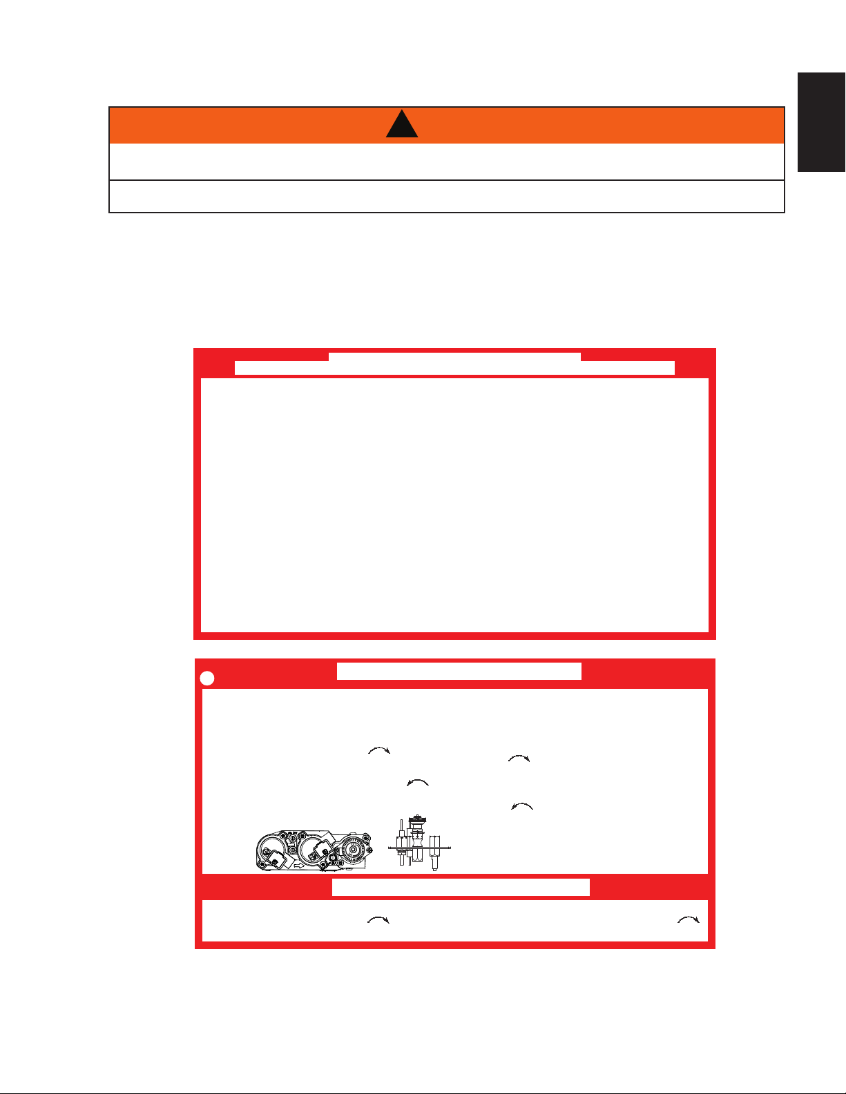
OPERATING INSTRUCTIONS / INSTRUCTIONS D’OPÉRATION
FOR YOUR SAFETY READ BEFORE OPERATING / POUR VOTRE SÉCURITÉ LIRE AVANT DE FAIRE FONCTIONNER
W385-0460 / E
W385-0460 / E
LIGHTING INSTRUCTIONS / INSTRUCTIONS D’ALLUMAGE
1. STOP! READ ALL INFORMATION OF OPERATING AND LIGHTING
INSTRUCTIONS BEFORE PROCEEDING.
2. TURN OFF ELECTRICAL POWER TO THE APPLIANCE.
3. THIS APPLIANCE IS EQUIPPED WITH AN IGNITION DEVICE WHICH
AUTOMATICALLY LIGHTS THE PILOT. DO NOT TRY TO LIGHT THE PILOT
BY HAND.
4. OPEN THE GLASS DOOR.
5. TURN MANUAL SHUTOFF VALVE CLOCKWISE TO OFF.
6. WAIT FIVE (5) MINUTES TO CLEAR OUT ANY GAS. IF YOU SMELL GAS,
INCLUDING NEAR THE FLOOR, STOP! FOLLOW “B” OF THE OPERATING
INSTRUCTIONS. IF YOU DON’T SMELL GAS, GO TO THE NEXT STEP.
7. TURN MANUAL SHUTOFF VALVE COUNTER-CLOCKWISE TO ON.
8. CLOSE THE GLASS DOOR.
9. TURN ON ALL ELECTRICAL POWER TO THE APPLIANCE.
10. TURN ON MAIN BURNER.
1. ARRÊTEZ! LISEZ TOUTES LES INSTRUCTIONS DE
FONCTIONNEMENT ET D’ALLUMAGE AVANT DE CONTINUER.
2. COUPEZ L’ALIMENTATION ÉLECTRIQUE À L’APPAREIL.
3. CET APPAREIL EST MUNI D’UN DISPOSITIF D’ALLUMAGE QUI
ALLUME LA VEILLEUSE AUTOMATIQUEMENT, N’ESSAYEZ PAS
D’ALLUMER LA VEILLEUSE MANUELLEMENT.
4. OUVREZ LA PORTE VITRÉE.
5. TOURNEZ LA SOUPAPE DE SECTIONNEMENT MANUELLE VERS LA
DROITE À « OFF ».
6. ATTENDEZ CINQ (5) MINUTES POUR QUE LE GAZ PUISSE
S’ÉCHAPPER. SI VOUS DÉTECTEZ UNE ODEUR DE GAZ, ARRÊTEZ!
SUIVEZ « B » DANS LES INSTRUCTIONS DE FONCTIONNEMENT.
S’IL N’Y A PAS D’ODEUR DE GAZ, PASSEZ À L’ÉTAPE SUIVANTE.
7. TOURNEZ LA SOUPAPE DE SECTIONNEMENT MANUELLE VERS LA
GAUCHE À « ON ».
8. FERMEZ LA PORTE VITRÉE.
9. RÉTABLISSEZ L’ALIMENTATION ÉLECTRIQUE AU FOYER.
10. ALLUMEZ LE BRÛLEUR PRINCIPAL.
1. TURN OFF ALL ELECTRICAL POWER TO THE APPLIANCE IF SERVICE IS
TO BE PERFORMED.
2. TURN MANUAL SHUTOFF VALVE CLOCKWISE TO OFF. DO NOT
FORCE.
1. COUPEZ L’ALIMENTATION ÉLECTRIQUE AU FOYER SI UN TRAVAIL
D’ENTRETIEN DOIT SE FAIRE.
2. TOURNEZ LA SOUPAPE D’ARRÉT MANUELLE VERS LA DROITE
À « OFF ». NE FORCEZ PAS.
TO TURN OFF GAS / INSTRUCTIONS POUR COUPER LE GAZ
MATERIAL:
LETTERING:
W415-1343 / A / 11.18.16
18
EN
6.2 XIR3 OPERATION
IF YOU DO NOT FOLLOW THESE INSTRUCTIONS EXACTLY, A FIRE OR EXPLOSION MAY RESULT
CAUSING PROPERTY DAMAGE, PERSONAL INJURY OR LOSS OF LIFE.
ALWAYS LIGHT THE PILOT WHETHER FOR THE FIRST TIME OR IF THE GAS SUPPLY HAS RUN OUT WITH
THE GLASS DOOR OPENED OR REMOVED.
!
WARNING
6.2.1 GENERAL TRANSMITTER LAYOUT
6.2.2 APPLIANCE OPERATION
A. Install 4 AA batteries into the receiver battery bay as indicated on the battery cover (+/-). (Only required
as back up to household electricity).
B.
Place the 3 position slider switch of the receiver in the “Remote” position.
C.
Using the end of a paper clip, or other similar object, insert the end of the paper clip into the hole
marked “PRG” on the receiver front cover. The receiver will “beep” three (3) times to indicate that it is
ready to synchronize with the transmitter.
D.
Install the 3 AAA batteries in the transmitter battery bay, located on the base of the transmitter.
With the batteries already installed in the transmitter, push the “ON” button. The receiver will “beep”
four times to indicate the transmitter’s command is accepted and set to the particular code of that
transmitter. The system is now initialized.
35.2A
6.2.3 HAND HELD REMOTE OPERATIONS
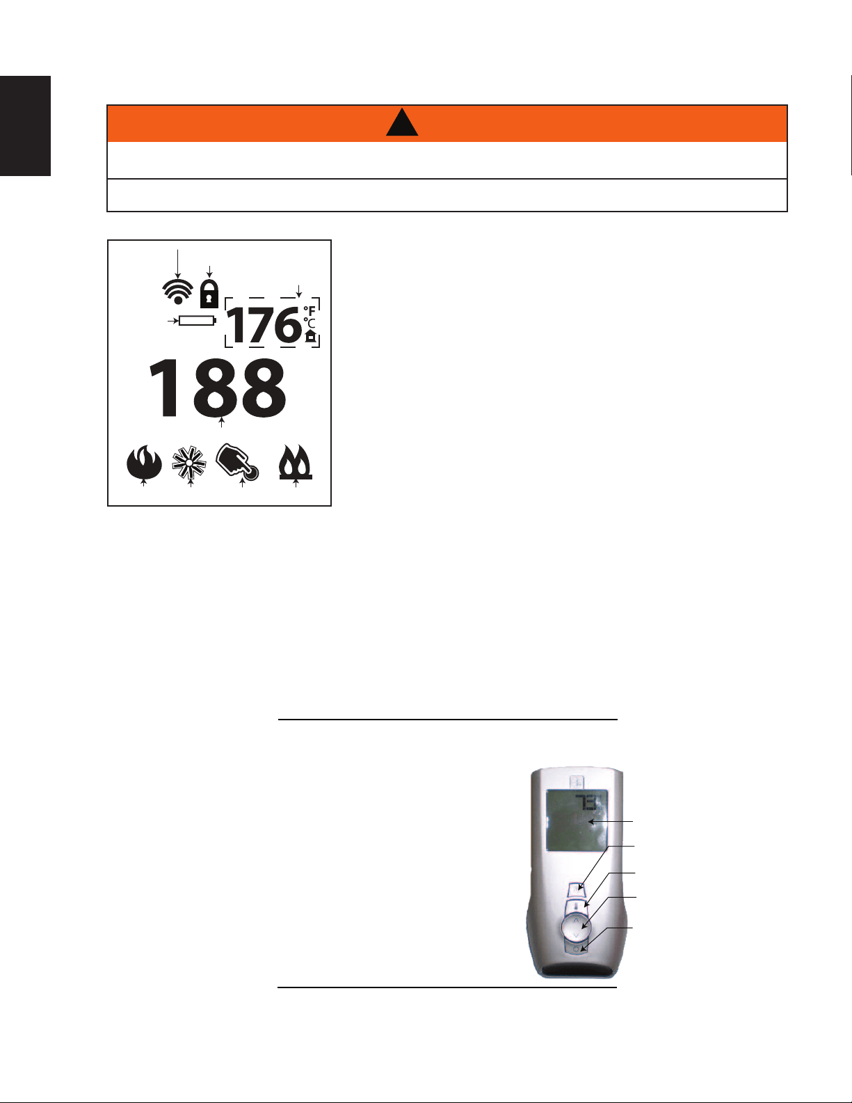
A. Press the ON/OFF key on the transmitter. The transmitter
display will show all active icons on the screen. A single
“beep” from the receiver will confi rm reception of the
command.
35.4A
BLUE LCD DISPLAY
ON/OFF KEY
UP/DOWN
ARROW KEY
MODE KEY
TEMPERATURE KEY
ROOM
TEMPERATURE
LOW BATTERY
ALARM
CHILD SAFETY
LOCK OUT
TRANSMISSION
AUX. OUTPUT
FANFLAME
TEMPERATURE SET POINT/ LEVEL/ STATUS
SPLIT VALVE
W415-1343 / A / 11.18.16
19
EN
The remote transmitter can operate as a room thermostat.
The thermostat can be set to a desired temperature to control the
comfort level in the room.
A. Press the Thermostat Key. The LCD display on the
Transmitter will show that the room is “ON” and the set
temperature is now displayed.
B. To adjust the set temperature, press the Up/Down Arrow
Keys until the desired set temperature is displayed on the
LCD screen of the Transmitter.
35.6
76
°F
68
ROOM TEMPERATURE
SET TEMPERATURE
6.2.4 TEMPERATURE DISPLAY
6.2.5 ROOM THERMOSTAT
A. With the system in the “OFF” position, press the
Temperature Key and the Mode Key at the same
time to change from degrees F to C.
B.
Look at the LCD screen on the Transmitter to
verify that a C or F is visible to the right of the
Room Temperature display.
35.5A
73
°F
23
°C
The Smart Thermostat function adjusts the fl ame height according to the difference
between the set temperature and the actual room temperatures. As the room
temperature gets closer to the set point the Smart Function will automatically adjust
the fl ame down.
A.
Press the thermostat key until the word “SMART” appears to the right of the
temperature bulb graphic.
B.
To adjust the set temperature, press the Up/Down arrow keys until the
desired set temperature is displayed on the LCD screen at the Transmitter.
35.7
76
°F
68
MAX
6.2.6 SMART THERMOSTAT
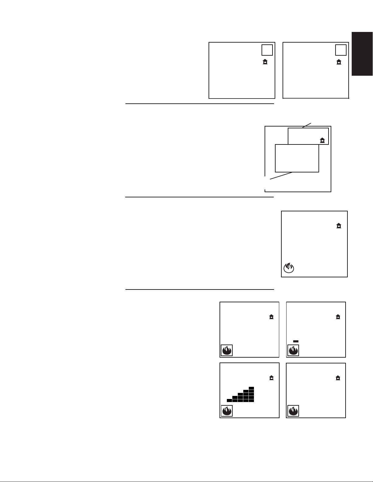
The remote control has six (6) fl ame levels. With the
system on and the fl ame level at the maximum, press
the Down Arrow Key once and it will reduce the fl ame
height by one step until the fl ame is turned off.
The Up Arrow Key will increase the fl ame height each
time it is pressed. If the Up Arrow Key is pressed while
the system is on but the fl ame is off, the fl ame will
come on the high position. A single “beep” will confi rm
reception of the command.
76
°F
OFF
76
°F
76
°F
76
°F
Hi
FLAME OFF
FLAME AT LEVEL 1
FLAME AT LEVEL 5 FLAME AT “HI” LEVEL 6
35.8A
6.2.7 FLAME HEIGHT
W415-1343 / A / 11.18.16
20
EN
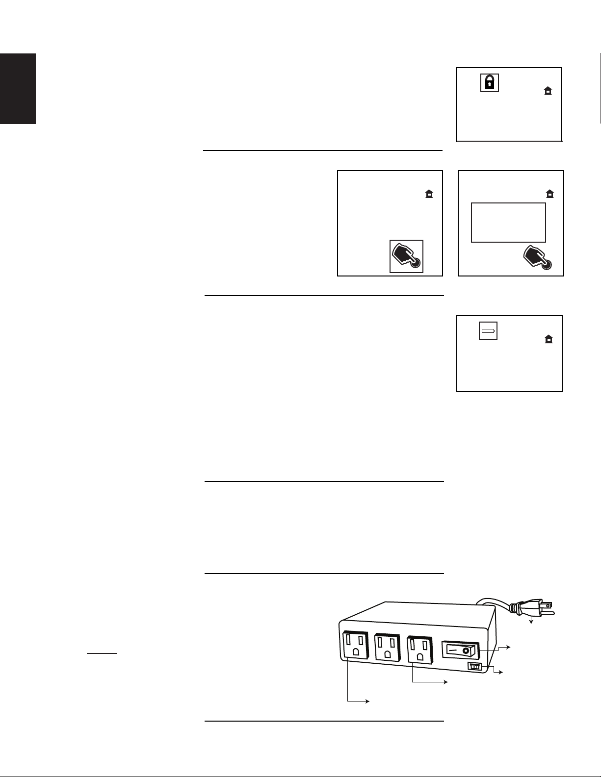
This function will lock the keys to avoid unsupervised operation.
A. Press the MODE and UP keys at the same time.
B. To de-activate this function, press the MODE and UP keys at the same
time.
35.10A
76
°F
6.2.8 CHILD PROOF FUNCTION
The auxiliary function controls the AUX power outlet on
the Control Module which controls the NIGHT LIGHT™.
A. Use the Mode Key to guide you to the AUX icon.
B. Pressing the Up Arrow Key will activate the
NIGHT LIGHT™.
C. Pressing the Down Arrow Key will turn the
NIGHT LIGHT™ off. A single “beep” will confi rm
the reception of the command.
35.12A
76
°F
OFF
76
°F
ON
6.2.9 NIGHT LIGHT
The control module offers a remotely actuated 120V AUX
outlet for the accent lights and a constantly powered
120V outlet.
NOTE: Control module ON/OFF switch should
always be in the “ON” position. If for any reason the
module is turned “OFF”, the components plugged
into the module won’t have power.
35.16
CONSTANTLY POWERED
120V OUTLET
120V AUX OUTLET
MAINS VOLTAGE
SUPPLY CORD
MODULE ON/OFF
SWITCH (SHOWN IN
THE ON POSITION)
COMMUNICATION
BUS (3 PIN)
6.2.10 LOW BATTERY / MANUAL BYPASS
6.2.11 IN THE EVENT OF A POWER FAILURE
If the receiver is equipped with batteries they will enable fl ame height control or ON/OFF function to control
the fi replace during a power failure. Refer to “APPLIANCE OPERATION” section when communications
between receiver and transmitter have been lost. The receiver will emit a “beep” sound to confi rm
programming has been successful once power is restored. During a power failure, if the fi replace was on, the
fl ame height will stay at the setting prior to the failure. If off when the failure occurs and then turned on, the
fl ame height will come on at “HI”. The fl ame height can then be controlled by the remote.
35.14A
The life span of the remote batteries depends on various factors: quality of the
batteries, the number of ignitions, etc.
When the transmitter batteries are low, a battery icon will appear on the LCD
display before all battery power is lost. When the batteries are replaced, this icon
will disappear.
When the receiver batteries are low, no “beep” will be emitted from the receiver
when it receives an ON/OFF command. This is an alert for the receiver that there’s
low battery. When the batteries are replaced, the “beep” will be emitted from the
receiver when the ON/OFF key is pressed.
If the batteries of the receiver or transmitter are low, the appliance can be turned on manually by sliding the
three position slider switch on the receiver to the “ON” position. This will bypass the remote control feature
and the appliance main burner will come on if the gas valve is in the “ON” position.
35.13A
76
°F
6.2.12 CONTROL MODULE
W415-1343 / A / 11.18.16
21
EN
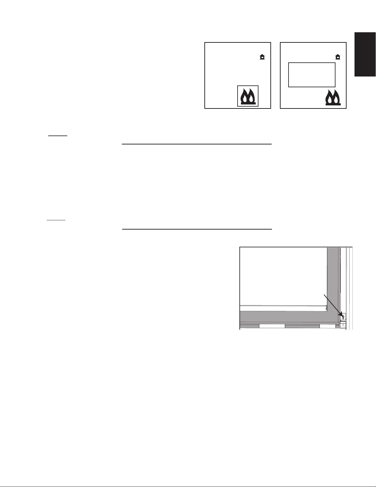
The split fl ow function controls the ability to turn ON/
OFF a second burner.
A. Use the mode key to guide you to the split fl ow
function.
B. Pressing the up arrow key will activate the
second burner.
C. Pressing the down arrow key will deactivate the
second burner. A single “beep” will confi rm the reception of the command.
NOTE:Thereisnowaytomodulatetheflameheightsseparately.
35.17A
76
°F
OFF
76
°F
ON
Your remote system may have a built in timer (in thermostat mode) that enables the blower (if equipped) to
cycle on and off automatically when the burner turns on and off. With the remote control fan speed preset at
the preferred speed, the blower will come on approximately 5 minutes after the main burner comes on and
will shut off approximately 12 minutes after the burner shuts off.
This time delay is designed to maximize the blower distribution of heated air.
If at any time the burner re-ignites before the twelve minutes are over, the fan will continue to run.
NOTE:
At any time in the sequence, the blower (if equipped) can be manually turned on/off using the
remote control.
35.19B
RIGHT SIDE OF
DOOR FRAME
(OPERATING SIDE)
ANTI CONDENSATION
CONTROL SWITCH
This appliance has the option to go from an electronic intermittent
pilot ignition to a standing pilot for cold climates.
6.2.13 SPLIT FLOW VALVE
6.2.14 TIMED BLOWER
6.3 ANTI CONDENSATION CONTROL SWITCH
W415-1343 / A / 11.18.16
22
EN
XIR3
NG
F 1/8"(3.2mm)
R 5/16"(8mm)
P
F 1/2"(12.7mm)
R 3/8"(9.5mm)
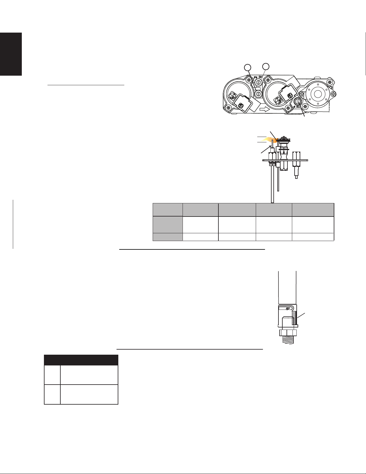
Adjust the pilot screw to provide properly sized fl ame. Turn in a
clockwise direction to reduce the gas fl ow.
Check Pressure Readings:
Inlet pressure can be checked by turning screw (A) counter-
clockwise 2 or 3 turns and then placing pressure gauge tubing
over the test point. Gauge should read as described on the chart
below. Check pressure with main burner operating on “HI”.
Outlet pressure can be checked the same as above using
screw (B). Gauge should read as described on the chart
below. Check pressure with main burner operating on “HI”.
AFTER TAKING PRESSURE READINGS, BE SURE TO
TURN SCREWS CLOCKWISE FIRMLY TO RESEAL. DO
NOT OVERTORQUE.
Leak test with a soap and water solution.
Prior to pilot adjustment, ensure that the pilot assembly
has not been painted. If overspray or painting of the pilot
assembly has occurred remove the paint from the pilot
assembly, or replace. Fine emery
cloth or a synthetic scrub pad (such as
Scotch-Brite
™)
can be used to remove
the paint from the pilot hood, electrode
and fl ame sensor.
*Maximum inlet pressure not to exceeed 13”.
39.1E
A
B
PILOT SCREW
FLAME MUST ENVELOP
UPPER 3/8” (9.5mm) TO 1/2”
(12.7mm) OF FLAME SENSOR
PILOT
BURNER
ELECTRODE
FLAME
SENSOR
3/8” - 1/2”
(9.5mm - 12.7mm)
Pressure
Inlet
Outlet
Natural Gas
(inches)
Natural Gas
(millibars)
Propane
(inches)
Propane
(millibars)
*7"
(MIN. 4.5”)
3.5"
13"
(MIN. 11")
10"
17.4mb
(MIN. 11.2mb)
8.7mb
32.4mb
(MIN. 27.4mb)
24.9mb
This appliance has an air shutter that has been factory set open according
to the chart below:
Regardless of venturi orientation, closing the air shutter will cause a more
yellow flame, but can lead to carbonization. Opening the air shutter will
cause a more blue flame, but can cause flame lifting from the burner ports.
The flame may not appear yellow immediately; allow 15 to 30 minutes for
the final flame colour to be established.
AIR SHUTTER ADJUSTMENT MUST ONLY BE DONE BY A QUALIFIED
INSTALLER!
AIR
SHUTTER
OPENING
VENTURI
BURNER
ORIFICE
49.1
7.0 ADJUSTMENTS
7.1 PILOT BURNER ADJUSTMENT
7.2 VENTURI ADJUSTMENT
W415-1343 / A / 11.18.16
23
EN
7.3 FLAME CHARACTERISTICS
It is important to periodically perform a visual check of the pilot
and burner fl ames. Compare them to the illustration provided. If
any fl ames appear abnormal, call a service person.
FLAME MUST ENVELOP
UPPER 3/8” (9.5mm) TO 1/2”
(12.7mm) OF FLAME SENSOR
PILOT
BURNER
ELECTRODE
FLAME
SENSOR
3/8” - 1/2”
(9.5mm - 12.7mm)
54.1B
W415-1343 / A / 11.18.16
24
EN
!
WARNING
THE FIREBOX BECOMES VERY HOT DURING OPERATION. LET THE APPLIANCE COOL
COMPLETELY OR WEAR HEAT RESISTANT GLOVES BEFORE CONDUCTING SERVICE.
NEVER VACUUM HOT EMBERS.
DO NOT PAINT THE PILOT ASSEMBLY.
• This appliance will require maintenance which should be planned on an annual basis.
• Service should include cleaning, battery replacement, venting inspection and inspection of the burner,
media and fi rebox. Refer to the door removal section and remove the door as instructed.
• Carefully remove media if necessary (logs, glass, brick panels etc).
• Using a vacuum with a soft brush attachment, gently remove any dirt, debris or carbon build up from the
logs, fi rebox and burner. For glass media, follow the installation instructions for pre-cleaning.
• Also gently remove any build-up on the pilot assembly including, if equipped; thermopile, thermocouple,
fl ame sensor and igniter.
NOTE: Clean fl ame sensor using a fi ne emery cloth or a synthetic scrub pad
(such as Scotch-Brite™) to remove any oxides.
Clean the pilot assembly using a vacuum with a soft
brush attachment.
It is important that the pilot assembly is not painted.
• Inspect all accessible gaskets and replace as required.
• Access the blower, if equipped and clean using a soft brush and vacuum.
• Re-assemble the various components in reverse order.
• Inspect the relief system. The appliance relieves through the main glass door or through the fl aps on the
8.0 MAINTENANCE
This appliance and its venting system should be inspected before use and at least annually by a qualifi ed
service person. The following suggested checks should be performed by a qualifi ed technician. The
appliance area must be kept clear and free of combustible materials, gasoline or other fl ammable vapors and
liquids. The fl ow of combustion and ventilation air must not be obstructed.
CAUTION: Label all wires prior to disconnection when servicing controls. Wiring errors can cause improper
and dangerous operation. Verify proper operation after servicing.
A. In order to properly clean the burner and pilot assembly, remove the logs, rocks and/or glass to
expose both assemblies.
B. Keep the control compartment, media, burner, air shutter opening and the area surrounding the logs
clean by vacuuming or brushing, at least once a year.
C. Check to see that all burner ports are burning. Clean out any of the ports which may not be burning
or are not burning properly.
D. Check to see that the pilot fl ame is large enough to engulf the fl ame sensor and/or thermocouple /
thermopile as well as reaches the burner.
E. Replace the cleaned logs, rocks or glass. Failure to properly position the media may cause carbon
which can be distributed inside of fi rebox and on exterior surfaces surrounding vent termination.
F. Check to see that the main burner ignites completely on all openings when turned on. A 5 to 10
second total light-up period is satisfactory. Service as required.
G. Check that the gasketing on the sides, top and bottom of the door is not broken or missing. Replace
if necessary.
H. If for any reason the vent air intake system is disassembled, re-install and re-seal per the instructions
provided for the initial installation.
I. Cleaning the safety barrier may be necessary due to excessive lint / dust from carpeting, pets, etc.
simply vacuum using the brush attachment.
J. Ensure the relief system performs effectively. Check that the gasket is not worn or damaged. Replace
if necessary.
40.1E
TURN OFF THE GAS AND ELECTRICAL POWER BEFORE SERVICING THE APPLIANCE.
APPLIANCE MAY BE HOT, DO NOT SERVICE UNTIL APPLIANCE HAS COOLED.
DO NOT USE ABRASIVE CLEANERS.
DO NOT PAINT THE PILOT ASSEMBLY.
MAINTENANCE
MAINTENANCE
MAINTENANCE
!
WARNING
8.1 ANNUAL MAINTENANCE
W415-1343 / A / 11.18.16
25
EN
8.2 CARE OF GLASS
5.1A
DO NOT CLEAN GLASS WHEN HOT! DO NOT USE
ABRASIVE CLEANERS TO CLEAN GLASS.
Buff lightly with a clean dry soft cloth. Clean both sides
of the glass after the fi rst 10 hours of operation with a
recommended fi replace glass cleaner. Do not use an
ammonia-based fi replace glass cleaner. Thereafter clean
as required. If the glass is not kept clean permanent
discoloration and / or blemishes may result.
HOT GLASS WILL
CAUSE BURNS.
DO NOT TOUCH GLASS
UNTIL COOLED.
NEVER ALLOW CHILDREN
TO TOUCH GLASS.
!
WARNING
8.3 CARE OF PLATED PARTS
6.1
If the appliance is equipped with plated parts, you must clean fi ngerprints or other marks from the plated
surfaces before operating the appliance for the fi rst time. Use a glass cleaner or vinegar and towel to clean.
If not cleaned properly before operating for the fi rst time, the marks can cause permanent blemishes on the
plating. After the plating is cured, the fi ngerprints and oils will not affect the fi nish and little maintenance
is required, just wipe clean as needed. Prolonged high temperature burning with the door ajar may cause
discolouration on plated parts.
NOTE: The protective wrap on plated parts is best removed when the assembly is at room temperature
but this can be improved if the assembly is warmed, using a hair dryer or similar heat source.
5.5.1A
This appliance is factory equipped with 5mm ceramic glass. Use only replacement parts as supplied by the
appliance manufacturer. DO NOT SUBSTITUTE MATERIALS.
NOTE: Care must be taken when removing and disposing of any broken glass or damaged
components. Be sure to vacuum up any broken glass from inside the appliance before operation.
!
WARNING
DO NOT USE SUBSTITUTE MATERIALS.
GLASS MAY BE HOT, DO NOT TOUCH GLASS UNTIL COOLED.
CARE MUST BE TAKEN WHEN REMOVING AND DISPOSING OF ANY BROKEN DOOR GLASS OR
DAMAGED COMPONENTS. BE SURE TO VACUUM UP ANY BROKEN GLASS FROM INSIDE THE
APPLIANCE BEFORE OPERATION.
DO NOT STRIKE, SLAM OR SCRATCH GLASS. DO NOT OPERATE APPLIANCE WITH GLASS
REMOVED, CRACKED, BROKEN OR SCRATCHED.
56.1C
Replacement glass/frame assembly shall be replaced as a complete unit as supplied by the
appliance manufacturer.
8.4 DOOR GLASS REPLACEMENT
37.1E
• Re-assemble the various components in reverse order.
• Inspect the relief system. The appliance relieves through the main glass door or through the fl aps on the
fi rebox top. Ensure they open freely, and close sealed.
• Check the gas control valve pilot and Hi / Lo knobs move freely (if equipped) – replace if any stiffness in
movement is experienced.
• Check for gas leaks on all gas connections up and downstream from the gas valve including the pilot
tube connections.
W415-1343 / A / 11.18.16
26
EN
B. Remove the 5 screws that secure
the rear log support in place. Lift the
support out.
C. Remove the 4 screws holding the
rear burner tube and lift it up and
out.
D. Remove the 5 screws that secure
the front burner support in place
and lift the support up and out.
E. Remove the 4 screws that secure
the front burner support in place
and lift the burner up and out.
A. Remove the glass door, see "DOOR REMOVAL AND INSTALLATION" section. Remove the
logs, see "FINISHING" section.
TURN OFF THE GAS AND ELECTRICAL POWER BEFORE SERVICING THE APPLIANCE.
THE APPLIANCE MAY BE HOT. DO NOT SERVICE APPLIANCE UNTIL IT HAS COOLED.
!
WARNING
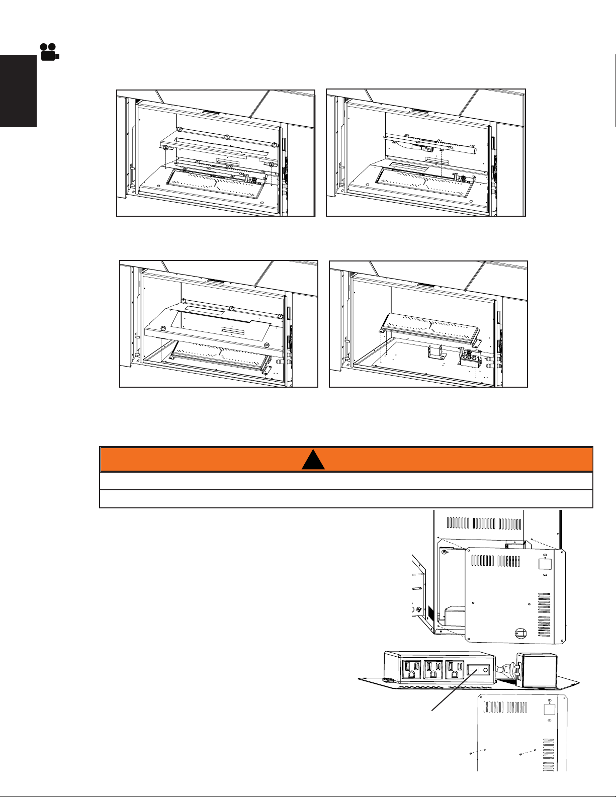
ACCESS PLATE
A. To access the fan control module, you must first pull out
the appliance, allowing enough room to access the left
access plate.
B. Remove the screws holding the access plate in position.
C. Unplug the fan control module from the
junction box. Unplug the night light plug and
blower plug (if applicable) from the
fan control module.
D. Remove the 2 screws securing the fan control to
the access plate and replace. NOTE: Ensure
that the ON/OFF switch is in the ON (-) position.
E. Reinstall the plugs and access plate
ON/OFF
SWITCH
8.5 BURNER REMOVAL
8.6 FCM REPLACEMENT
W415-1343 / A / 11.18.16
27
EN
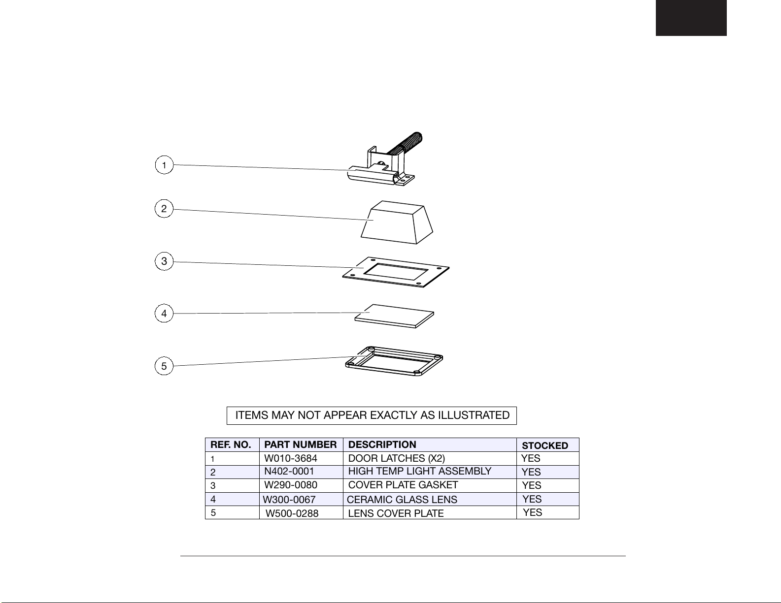
8.7 NIGHT LIGHT™ REPLACEMENT
Your appliance comes equipped with our “Night Light™”. The light has been pre-wired and is controlled from
the remote control.
If the lamp or lens needs to be replaced, follow the instructions below.
A. Unplug the fan control module from the junction box located behind
the left access panel.
B. Remove the four screws that secure the lens frame. This frame
retains the glass lens. The lamp can now be accessed.
NOTE: Do not handle the lamp (bulb) with bare fingers, protect with a
clean dry cloth.
The lamp will pull straight out of the socket. Replace with Wolf Steel parts only, as
lamp and lens are special “high temperature” products. When re-installing, ensure
integrity of gasket seal.
THE FIREBOX MUST BE SEALED.
Over-tightening the screws could break the lens. “Light Leakage” from the upper
area may be observed. The holes in the lamp housing are necessary for ventilation
and must not be covered.
GASKET
LENS
FRAME
COLOURED SIDE UP
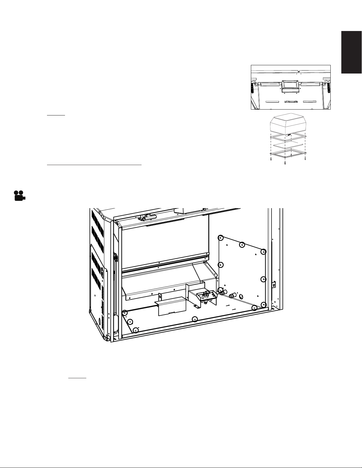
A. Remove the glass door. See "DOOR REMOVAL AND INSTALLATION" section. Remove the burners,
see "BURNER REMOVAL" section.
B. Remove the 14 screws holding the valve train in place.
NOTE: A new gasket may be required when reinstalling the valve train assembly. Contact your
local authorized dealer/distributor.
C. Carefully lift the valve train assembly out far enough to access the manual shut off valve and turn to
the off position. Disconnect the flex connector from the valve. You may now lift the valve train out of
the appliance.
8.8 VALVE TRAIN REPLACEMENT

W415-1343 / A / 11.18.16
28
EN
9.0 REPLACEMENTS
41.1C
Contact your dealer for questions concerning prices and policies on replacement parts. Normally, all parts
can be ordered through your Authorized dealer / distributor.
FOR WARRANTY REPLACEMENT PARTS, A PHOTOCOPY OF THE ORIGINAL INVOICE WILL BE
REQUIRED TO HONOUR THE CLAIM.
When ordering replacement parts always give the following information:
•
Model & Serial Number of appliance
•
Installation date of appliance
•
Part number
•
Description of part
•
Finish
PARTS, PART NUMBERS AND AVAILABILITY ARE SUBJECT TO CHANGE WITHOUT NOTICE.
PARTS IDENTIFIED AS STOCKED WILL BE DELIVERED WITHIN 2 TO 5 BUSINESS DAYS FOR MOST
DELIVERY DESTINATIONS.
PARTS NOT IDENTIFIED AS STOCKED WILL BE DELIVERED WITHIN A 2 TO 4 WEEK PERIOD, FOR
MOST CASES.
PARTS IDENTIFIED AS ‘SO’ ARE SPECIAL ORDER AND CAN TAKE UP TO 90 DAYS FOR DELIVERY.
FAILURE TO POSITION THE PARTS IN ACCORDANCE WITH THIS MANUAL OR FAILURE TO USE
ONLY PARTS SPECIFICALLY APPROVED WITH THIS APPLIANCE MAY RESULT IN PROPERTY
DAMAGE OR PERSONAL INJURY.
!
WARNING
W415-1343 / A / 11.18.16
29
EN
13
6
9
8
7
14
5
15
11
10
1
13
7
10
9
8
14
6
5
15
4
12
11
3
2
ITEMS MAY NOT APPEAR EXACTLY AS ILLUSTRATED
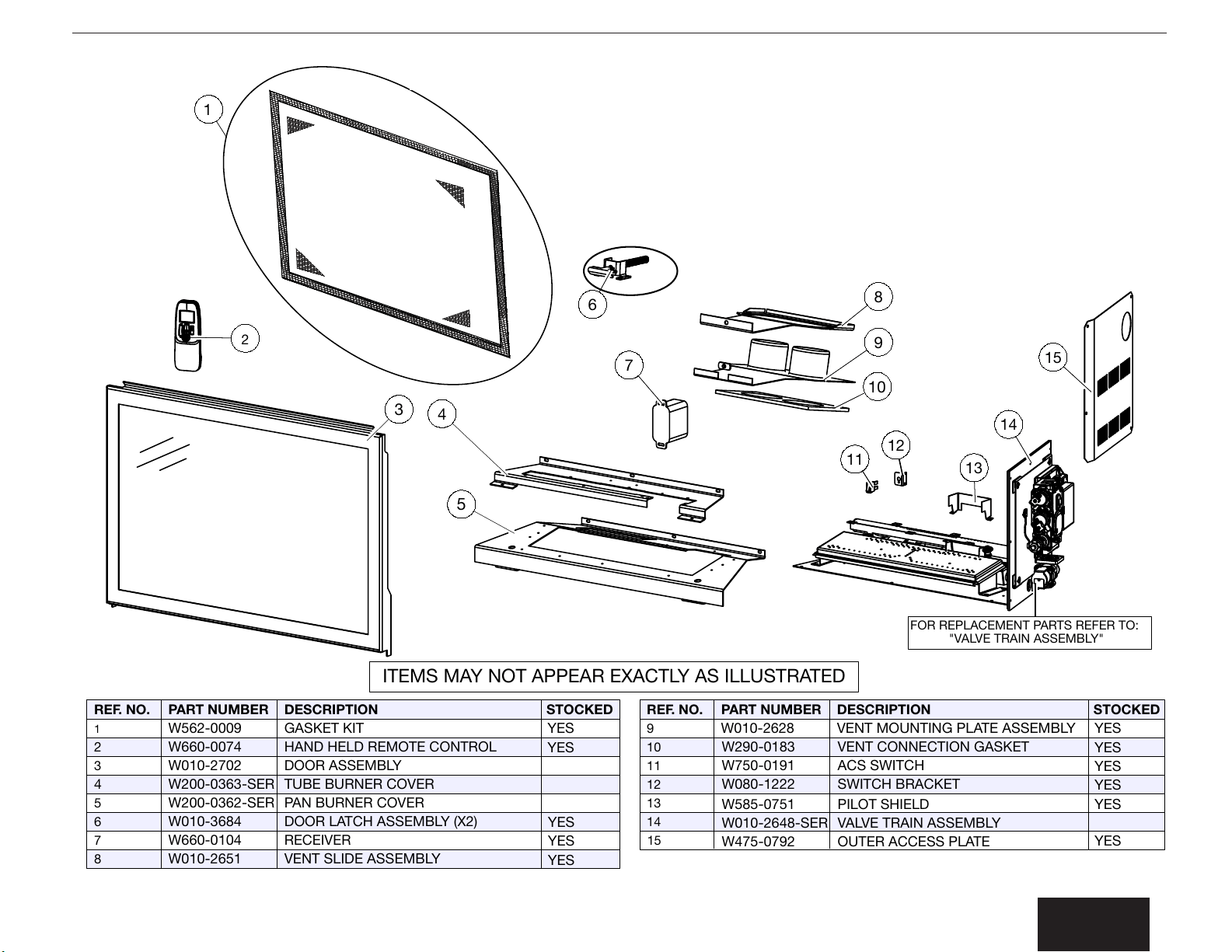
FOR REPLACEMENT PARTS REFER TO:
"VALVE TRAIN ASSEMBLY"
REF. NO.
PART NUMBER
DESCRIPTION
STOCKED
1
2
3
4
5
6
7
8
REF. NO.
PART NUMBER
DESCRIPTION
STOCKED
9
10
11
12
13
14
W290-0183
VENT CONNECTION GASKET
W750-0191
ACS SWITCH
W080-1222
SWITCH BRACKET
W585-0751
PILOT SHIELD
W010-2648-SER
VALVE TRAIN ASSEMBLY
W475-0792
OUTER ACCESS PLATE
W010-2628
VENT MOUNTING PLATE ASSEMBLY
15
W660-0074
HAND HELD REMOTE CONTROL
YES
YES
YES
YES
YES
YES
YES
YES
YES
YES
YES
W010-2702
DOOR ASSEMBLY
W200-0363-SER
TUBE BURNER COVER
W200-0362-SER
PAN BURNER COVER
W010-3684
DOOR LATCH ASSEMBLY (X2)
W660-0104
RECEIVER
W010-2651
VENT SLIDE ASSEMBLY
1
GASKET KIT
W562-0009
X2
9.1 OVERVIEW
W415-1343 / A / 11.18.16
30
EN
REF. #
PART #
DESCRIPTION
STOCKED
STOCKED
1
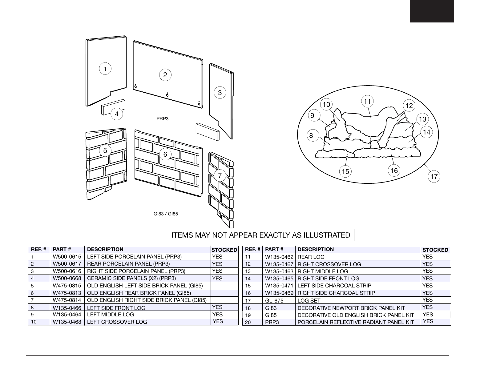
W500-0615
LEFT SIDE PORCELAIN PANEL (PRP3)
YES
YES
YES
YES
YES
YES
YES
YES
YES
YES
YES
YES
YES
YES
YES
YES
YES
2
W500-0617
REAR PORCELAIN PANEL (PRP3)
3
W500-0616
RIGHT SIDE PORCELAIN PANEL (PRP3)
4
5
REF. #
PART #
DESCRIPTION
W135-0468
LEFT CROSSOVER LOG
1
6
2
7
3
6
7
8
9
PRP3
GI83 / GI85
ITEMS MAY NOT APPEAR EXACTLY AS ILLUSTRATED
5
4
10
W475-0815
OLD ENGLISH LEFT SIDE BRICK PANEL (GI85)
W475-0813
OLD ENGLISH REAR BRICK PANEL (GI85)
W475-0814
OLD ENGLISH RIGHT SIDE BRICK PANEL (GI85)
W500-0668
CERAMIC SIDE PANELS (X2) (PRP3)
GI83
DECORATIVE NEWPORT BRICK PANEL KIT
GI85
DECORATIVE OLD ENGLISH BRICK PANEL KIT
W135-0465
RIGHT SIDE FRONT LOG
W135-0471
LEFT SIDE CHARCOAL STRIP
W135-0462
REAR LOG
W135-0467
RIGHT CROSSOVER LOG
W135-0466
LEFT SIDE FRONT LOG
W135-0469
RIGHT SIDE CHARCOAL STRIP
GL-675
LOG SET
17
18
13
14
11
12
15
16
19
PRP3
PORCELAIN REFLECTIVE RADIANT PANEL KIT
20
GL-675
17
8
9
10
11
13
14
16
15
12
W135-0464
LEFT MIDDLE LOG
RIGHT MIDDLE LOG
W135-0463
STOCKED
9.2 OVERVIEW (PG. 2)
W415-1343 / A / 11.18.16
31
EN
4
2
1
12
9
7
8
6
14
13
11
10
15
16
17
18
19
20
21
5
2
3
1
14
11
9
10
8
16
15
13
12
17
18
19
20
21
22
23
ITEMS MAY NOT APPEAR EXACTLY AS ILLUSTRATED
W175-0338
XIR3 VALVE TRAIN ASSEMBLY
REF. #
PART #
DESCRIPTION
STOCKED
1
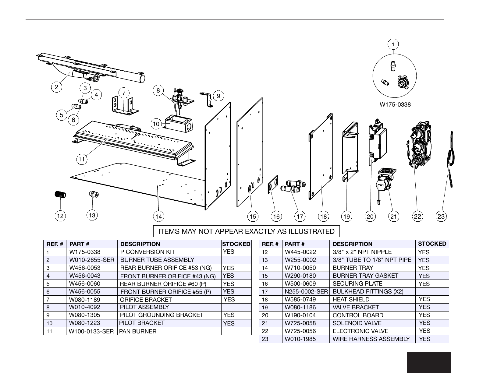
W175-0338
P CONVERSION KIT
2
W010-2655-SER
BURNER TUBE ASSEMBLY
3
W456-0053
REAR BURNER ORIFICE #53 (NG)
4
W456-0043
FRONT BURNER ORIFICE #43 (NG)
5
6
7
8
9
10
11
REF. #
PART #
DESCRIPTION
12
13
14
15
16
17
18
19
20
21
57
22
W456-0060
23
W456-0055
REAR BURNER ORIFICE #60 (P)
FRONT BURNER ORIFICE #55 (P)
W710-0050
W290-0180
W500-0609
N255-0002-SER
W585-0749
W080-1186
W190-0104
W725-0058
W725-0056
W010-1985
BURNER TRAY
BURNER TRAY GASKET
SECURING PLATE
BULKHEAD FITTINGS (X2)
HEAT SHIELD
VALVE BRACKET
CONTROL BOARD
SOLENOID VALVE
ELECTRONIC VALVE
WIRE HARNESS ASSEMBLY
W445-0022
3/8" x 2" NPT NIPPLE
W255-0002
3/8" TUBE TO 1/8" NPT PIPE
W100-0133-SER
PAN BURNER
W080-1223
PILOT BRACKET
W080-1305
PILOT GROUNDING BRACKET
W010-4092
PILOT ASSEMBLY
W080-1189
ORIFICE BRACKET
46
4
STOCKED
YES
YES
YES
YES
YES
YES
YES
YES
YES
YES
YES
YES
YES
YES
YES
YES
YES
YES
YES
9.3 VALVE TRAIN ASSEMBLY
W415-1343 / A / 11.18.16
32
EN
6
5
4
1
3
5
4
3
1
2
ITEMS MAY NOT APPEAR EXACTLY AS ILLUSTRATED
REF. NO.
PART NUMBER
DESCRIPTION
1
W010-3684
DOOR LATCHES (X2)
YES
YES
YES
YES
YES
2
3
N402-0001
HIGH TEMP LIGHT ASSEMBLY
4
W290-0080
COVER PLATE GASKET
5
W300-0067
CERAMIC GLASS LENS
W500-0288
LENS COVER PLATE
STOCKED
9.4 FIREBOX TOP ASSEMBLY
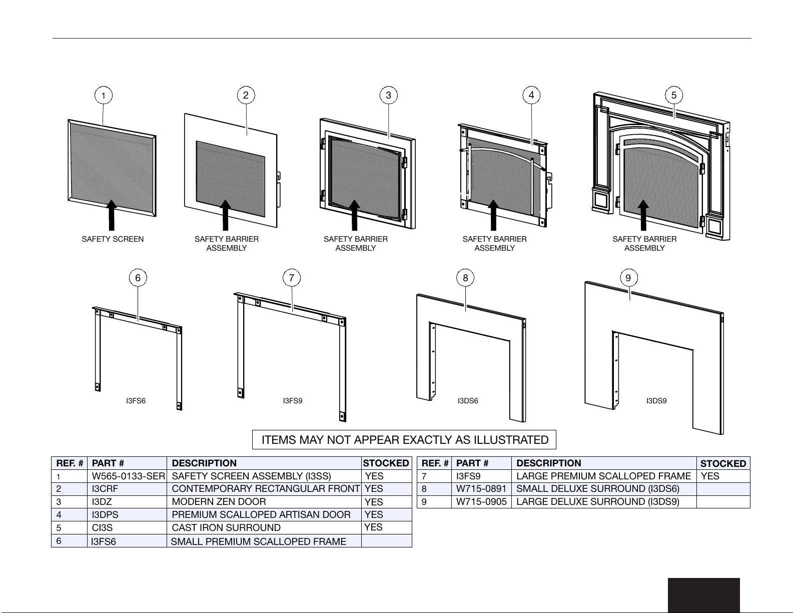
W415-1343 / A / 11.18.16
33
EN
1
5
3
4
11
10
2
9
8
1
5
3
4
9
8
2
7
6
ITEMS MAY NOT APPEAR EXACTLY AS ILLUSTRATED
XIR3 ACCESSORIES (Page 1)
REF. #
PART #
DESCRIPTION
1
W565-0133-SER
SAFETY SCREEN ASSEMBLY (I3SS)
2
I3CRF
CONTEMPORARY RECTANGULAR FRONT
3
I3DZ
MODERN ZEN DOOR
4
I3DPS
PREMIUM SCALLOPED ARTISAN DOOR
5
CI3S
CAST IRON SURROUND
6
REF. #
PART #
DESCRIPTION
STOCKED
STOCKED
7
8
I3FS6
SMALL PREMIUM SCALLOPED FRAME
9
I3FS9
LARGE PREMIUM SCALLOPED FRAME
W715-0891
SMALL DELUXE SURROUND (I3DS6)
W715-0905
LARGE DELUXE SURROUND (I3DS9)
I3FS6
I3FS9
I3DS6
I3DS9
SAFETY BARRIER
ASSEMBLY
SAFETY SCREEN
SAFETY BARRIER
ASSEMBLY
SAFETY BARRIER
ASSEMBLY
SAFETY BARRIER
ASSEMBLY
YES
YES
YES
YES
YES
YES
10.0 ACCESSORIES
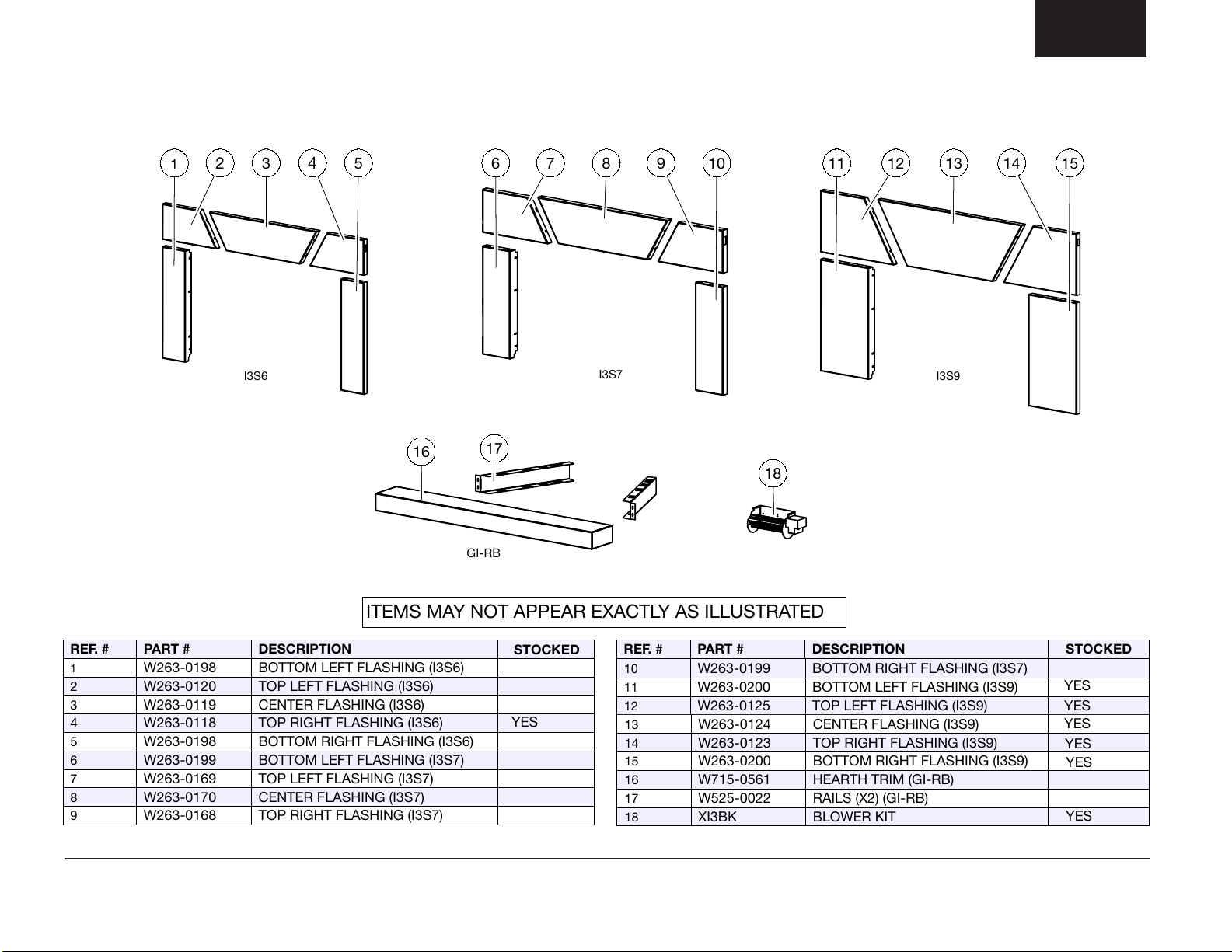
W415-1343 / A / 11.18.16
34
EN
6
7
8
9
10
1
2
3
5
4
11
12
13
15
14
17
16
18
6
7
8
9
10
1
2
3
5
4
11
12
13
15
14
17
16
18
ITEMS MAY NOT APPEAR EXACTLY AS ILLUSTRATED
I3S6
I3S9
I3S7
GI-RB
XIR3 ACCESSORIES (Page 2)
REF. #
PART #
DESCRIPTION
STOCKED
1
W263-0198
BOTTOM LEFT FLASHING (I3S6)
2
W263-0120
TOP LEFT FLASHING (I3S6)
3
W263-0119
CENTER FLASHING (I3S6)
4
W263-0118
TOP RIGHT FLASHING (I3S6)
5
W263-0198
BOTTOM RIGHT FLASHING (I3S6)
6
W263-0199
BOTTOM LEFT FLASHING (I3S7)
7
W263-0169
TOP LEFT FLASHING (I3S7)
8
W263-0170
CENTER FLASHING (I3S7)
9
W263-0168
TOP RIGHT FLASHING (I3S7)
REF. #
PART #
DESCRIPTION
10
W263-0199
BOTTOM RIGHT FLASHING (I3S7)
11
W263-0200
BOTTOM LEFT FLASHING (I3S9)
12
W263-0125
TOP LEFT FLASHING (I3S9)
13
W263-0124
CENTER FLASHING (I3S9)
14
W263-0123
TOP RIGHT FLASHING (I3S9)
15
W263-0200
BOTTOM RIGHT FLASHING (I3S9)
16
W715-0561
HEARTH TRIM (GI-RB)
17
W525-0022
RAILS (X2) (GI-RB)
18
XI3BK
BLOWER KIT
STOCKED
YES
YES
YES
YES
YES
YES
YES
10.1 ACCESSORIES (PG. 2)
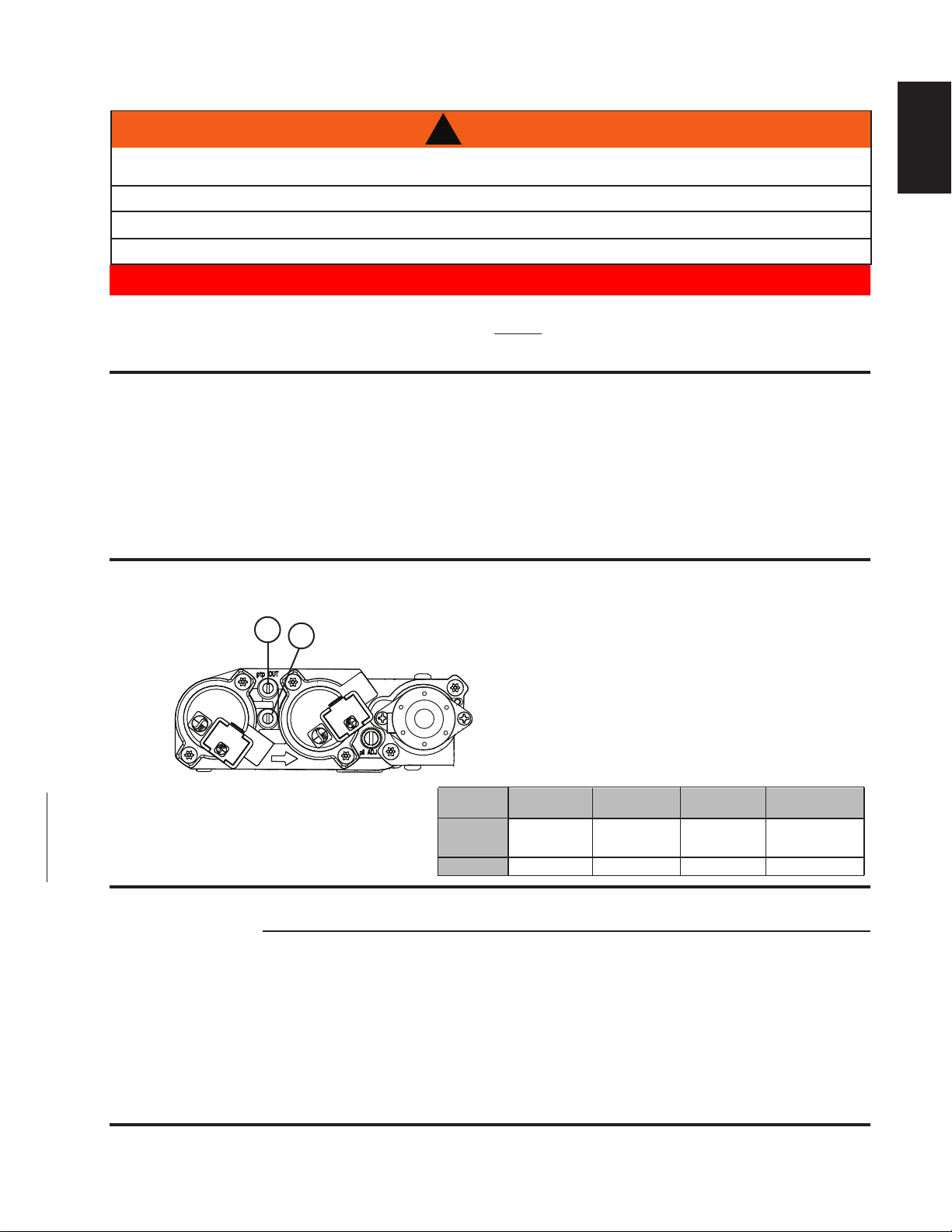
W415-1343 / A / 11.18.16
35
EN
11.0 TROUBLESHOOTING
SYMPTOM PROBLEM TEST SOLUTION
Remote controls
Crystalite / Night
light but no spark or
fl ame.
Remote is locked out. - Reset by turning power source off then on.
NOTE: If back up batteries are installed, they
must also be removed to re-program.
Main burner fl ame
is a blue, lazy,
transparent fl ame.
Blockage in vent. - Remove blockage. In really cold conditions, ice
buildup may occur on the terminal and should
be removed as required. To minimize this from
happening again, it is recommended that the vent
lengths that pass through unheated spaces (attics,
garages, crawl spaces) be wrapped with an insulated
mylar sleeve. Prevent sleeve from sagging. Contact
your local authorized dealer for more information.
Incorrect installation. - Refer to “VENTING” section to ensure correct
installation.
Flames are
consistently
too large or too
small. Carboning
occurs.
Appliance is over-fi red or
underfi red.
- Check pressure readings:
Inlet pressure can be checked by turning screw (A)
counter-clockwise 2 or 3 turns and then placing
pressure gauge tubing over the test point. Gauge
should read as described on the chart below. Check
that main burner is operating on ‘HI’. Outlet pressure
can be checked the same as above using screw
(B). Gauge should read as described on the chart
below. Check that main burner is operating on ‘HI’.
AFTER TAKING PRESSURE READINGS, BE SURE
TO TURN SCREWS CLOCKWISE FIRMLY TO
RESEAL. DO NOT OVER TORQUE.
Leak test with a soap and water solution.
Carbon is being
deposited on
glass, logs,
rocks, media
or combustion
chamber
surfaces.
Air shutter has become
blocked.
- Ensure air shutter opening is free of lint or other
obstructions.
Flame is impinging on
the glass, logs, rocks,
media or combustion
chamber.
- Check that the glass, logs, rocks, media are correctly
positioned.
- Open air shutter to increase the primary air.
- Check the input rate: check the manifold pressure
and orifi ce size as specifi ed by the rating plate.
- Check that the door gasketing is not broken or
missing and that the seal is tight.
- Check that both vent liners are free of holes and well
sealed at all joints.
- Check that minimum rise per foot (meters) has been
adhered to for any horizontal venting.
White / grey fi lm Sulphur from fuel is being - Clean the glass with a recommended gas fi replace
A
B
!
WARNING
ALWAYS LIGHT THE PILOT WHETHER FOR THE FIRST TIME OR IF THE GAS SUPPLY HAS RUN OUT,
WITH THE GLASS DOOR OPEN OR REMOVED.
TURN OFF THE GAS AND ELECTRICAL POWER BEFORE SERVICING THE APPLIANCE.
APPLIANCE MAY BE HOT, DO NOT SERVICE UNTIL APPLIANCE HAS COOLED.
DO NOT USE ABRASIVE CLEANERS.
Pressure
Inlet
Outlet
Natural Gas
(inches)
Natural Gas
(millibars)
Propane
(inches)
Propane
(millibars)
*7"
(MIN. 4.5”)
3.5"
13"
(MIN. 11")
10"
17.4mb
(MIN. 11.2mb)
8.7mb
32.4mb
(MIN. 27.4mb)
24.9mb
*Maximum inlet pressure
not to exceed 13”

W415-1343 / A / 11.18.16
36
EN
SYMPTOM PROBLEM TEST SOLUTION
Exhaust fumes
smelled in room,
headaches.
Appliance is spilling. - Check door seal.
- Check for exhaust damage.
- Check that venting is installed correctly.
- Room is in negative pressure; increase fresh air supply.
Pilot will not light.
Makes noise with
no spark at pilot
burner.
Wiring. - Verify the wire for the sensor and the wire for the
ignitor are connected to the correct terminals (not
reverse) on the module and pilot assembly.
Loose connection. - Verify no loose connections, electrical shorts in the
wiring or ground out to any metal object.
Igniter Spark gap is
incorrect.
- Spark gap of the ignitor to the pilot should be .125”
(3.2mm).
Pilot will not light.
Makes no noise
with no spark
at pilot burner.
Crystalites™ and
(optional) blower
operates.
A shorted or loose
connection.
- Remove and reinstall the wiring harness that plugs into
the module.
- Remove and verify continuity of each wire in the wiring
harness.
Module is not
grounded.
- Verify the valve and pilot assemblies are properly
grounded to the metal chassis of the fi replace.
Ignition box has been
locked out.
Choose one of the 4 methods below to reset the system.
1. To reset ignition box when locked out. Turn off power
supply and remove batteries (if used) from the back up
battery pack.
2. To reset the DFC Board when the board goes into
a lock out condition and the LED is blinking 3 times
using the transmitter ON/OFF button:
Step 1: Turn the system off by pressing the ON/
OFF button to turn the system off.
Step 2: After approximately 2 seconds press the
ON/OFF button on the transmitter again. THE DFC
Board will reset and the ignition sequence will start
again.
3. To reset the DFC Board when the board goes into a
lock out condition and the LED is blinking 3 times by
cycling fl ame:
Step 1: In the manual fl ame control mode, use
the down arrow button to reduce the fl ame to
off, indicated by the word OFF displayed on the
trasmitter LCD screen.
Step 2: Wait approximately 2 seconds and press
the up arrow button, the ignition sequence will
start.
NOTE: Starting from OFF, press the ON button on the transmitter. Approximately 4
seconds after the ON/OFF button is pressed the ignition board will start the spark.
The fi rst try for ignition will last approximately 60 seconds. If there is no fl ame ignition
(rectifi cation) the board will stop sparking for approximately 35 seconds. After the
wait time the board will start the second try for ignition by sparking for approximately
60 seconds. If there is still no positive ignition, the board will go into lock out.
42.1_2A
42.1D
adhered to for any horizontal venting.
White / grey fi lm
forms.
Sulphur from fuel is being
deposited on glass, logs
or combustion chamber
surfaces.
- Clean the glass with a recommended gas fi replace
glass cleaner. DO NOT CLEAN GLASS WHEN HOT.
- If deposits are not cleaned off regularly, the glass
may become permanently marked.

W415-1343 / A / 11.18.16
37
EN
42.1_3B
SYMPTOM PROBLEM TEST SOLUTION
Pilot sparks but
will not light.
Gas supply. - Verify that the incoming gas line ball valve is “Open”.
- Verify that the inlet pressure reading is within
acceptable limits, inlet pressures must not exceed
13” W.C. (34.9mb).
Module is not grounded. - Verify the value and pilot assemblies are properly
grounded to the metal chassis of the fi replace.
Out of propane gas. - Fill the tank.
Continues to
spark and pilot
lights, but main
burner will not
light.
Short or loose connection
in sensor rod.
Verify all connections. Verify the connections
from the pilot assembly are tight; also verify these
connections are not grounding out to any metal.
Poor fl ame rectifi cation or
contaminated sensor rod.
- Verify the fl ame is engulfi ng the sensor rod. This
will increase the fl ame rectifi cation. Verify correct
pilot orifi ce is installed and inlet gas specifi cations
to manual. (Remember, the fl ame carries the
rectifi cation current, not the gas. If the fl ame lifts
from pilot hood, the circuit is broken. A wrong orifi ce
or too high of an inlet pressure can cause the pilot
fl ame to lift.) The sensor rod may need cleaning.
Poor grounding between
pilot assembly and gas
valve.
- Verify that the wire harness is fi rmly connected to
module.
Damaged pilot or dirty
sensor rod.
- Verify that the ceramic insulator around the sensor
rod is not cracked, damaged, or loose. Verify the
connection from the sensor rod to the sensor
wire. Clean sensor rod with a green Scotch-Brite
pad to remove any contamination that may have
accumulated on the sensor rod. Verify continuity with
multimeter with ohms set at the lowest range.
Pilot has been painted
- Using a scrub pad, remove the paint from the pilot
hood, ignitor and fl ame sensor.
Appliance won’t
perform any
functions.
Receiver switch is in the
wrong position.
- Verify that the 3 position switch on the receiver is in
the “REMOTE” position (middle).
No power to the system. - Check breaker to verify it’s in the “ON” position.
Transmitter isn’t
operational.
- Check battery power and battery orientation.
Night light or
(optional) blower
won’t function
Control module switch is
in the wrong position.
- Verify ON/OFF switch is in the “I” position which
denotes on.
COM switch is
unplugged.
- Verify “COM” switch is plugged into the front of the
control module.
W415-1343 / A / 11.18.16
38
EN
NAPOLEON warrants its products against manufacturing defects to the original purchaser only. Registering your warranty is not
necessary. Simply provide your proof of purchase along with the model and serial number to make a warranty claim. NAPOLEON
reserves the right to have its representative inspect any product or part thereof prior to honouring any warranty claim. Provided
that the purchase was made through an authorized NAPOLEON dealer your appliance is subject to the following conditions and
limitations:
Warranty coverage begins on the date of original installation.
This factory warranty is non-transferable and may not be extended whatsoever by any of our representatives.
The gas appliance must be installed by a licensed, authorized service technician or contractor. Installation must be done in
accordance with the installation instructions included with the product and all local and national building and fi re codes.
This limited warranty does not cover damages caused by misuse, lack of maintenance, accident, alterations, abuse or neglect and
parts installed from other manufacturers will nullify this warranty.
This limited warranty further does not cover any scratches, dents, corrosion or discoloring caused by excessive heat, abrasive and
chemical cleaners nor chipping on porcelain enamel parts, mechanical breakage of PHAZER™ logs and embers.
This warranty extends to the repair or replacement of warranted parts which are defective in material or workmanship provided that
the product has been operated in accordance with the operation instructions and under normal conditions.
After the fi rst year, with respect to this President’s Lifetime Limited Warranty, NAPOLEON may, at its discretion, fully discharge all
obligations with respect to this warranty by refunding to the original warranted purchaser the wholesale price of any warranted but
defective part(s).
NAPOLEON will not be responsible for installation, labour or any other expenses related to the reinstallation of a warranted part and
such expenses are not covered by this warranty.
Notwithstanding any provisions contained in the President’s Lifetime Limited Warranty, NAPOLEON’S responsibility under this
warranty is defi ned as above and it shall not in any event extend to any incidental, consequential or indirect damages.
This warranty defi nes the obligations and liability of NAPOLEON with respect to the NAPOLEON gas appliance and any other
warranties expressed or implied with respect to this product, its components or accessories are excluded.
NAPOLEON neither assumes, nor authorizes any third party to assume, on its behalf, any other liabilities with respect to the sale of
this product.
NAPOLEON will not be responsible for: over-fi ring, downdrafts, spillage caused by environmental conditions such as rooftops,
buildings, nearby trees, hills, mountains, inadequate vents or ventilation, excessive venting confi gurations, insuffi cient makeup air, or
negative air pressures which may or may not be caused by mechanical systems such as exhaust fans, furnaces, clothes dryers, etc.
Any damages to the appliance, combustion chamber, heat exchanger, plated trim or other components due to water, weather
damage, long periods of dampness, condensation, damaging chemicals or cleaners will not be the responsibility of NAPOLEON.
All parts replaced under the President’s Limited Lifetime Warranty Policy are subject to a single claim.
During the fi rst 10 years NAPOLEON will replace or repair the defective parts covered by the lifetime warranty at our discretion free of
charge. From 10 years to life, NAPOLEON will provide replacement parts at 50% of the current retail price.
All parts replaced under the warranty will be covered for a period of 90 days from the date of their installation.
The manufacturer may require that defective parts or products be returned or that digital pictures be provided to support the
claim. Returned products are to be shipped prepaid to the manufacturer for investigation. If a product is found to be defective, the
manufacturer will repair or replace such defect.
Before shipping your appliance or defective components, your dealer must obtain an authorization number. Any merchandise
shipped without authorization will be refused and returned to sender.
Shipping costs are not covered under this warranty.
Additional service fees may apply if you are seeking warranty service from a dealer.
Warranty labour allowance is only for the replacement of the warranted part. Travel, diagnostic tests, shipping and other related
charges are not covered by this warranty.
2.1D
NAPOLEON products are manufactured under the strict Standard of the world recognized ISO 9001 : 2008 Quality
Assurance Certifi cate.
NAPOLEON products are designed with superior components and materials assembled by trained craftsmen who take
great pride in their work. The burner and valve assembly are leak and test-fi red at a quality test station. The complete
appliance is again thoroughly inspected by a qualifi ed technician before packaging to ensure that you, the customer,
receives the quality product that you expect from NAPOLEON.
The following materials and workmanship in your new NAPOLEON gas appliance are warranted against defects for as
long as you own the appliance. This covers: combustion chamber, heat exchanger, stainless steel burner, Phazer™
logs and embers, rocks, ceramic glass (thermal breakage only), gold plated parts against tarnishing, porcelainized
enameled components and aluminum extrusion trims.*
Electrical (110V and millivolt) components and wearable parts are covered and NAPOLEON will provide replacement
parts free of charge during the fi rst year of the limited warranty. This covers: blowers, gas valves, thermal switches,
switches, wiring, remote controls, ignitors, gaskets and pilot assemblies.*
Labour related to warranty repair is covered free of charge during the fi rst year. Repair work, however, requires
the prior approval of an authorized company offi cial. Labour costs to the account of NAPOLEON are based on a
predetermined rate schedule and any repair work must be done through an authorized NAPOLEON dealer.
* Construction of models vary. Warranty applies only to components included with your specifi c appliance.
NAPOLEON GAS APPLIANCE PRESIDENT’S LIFETIME LIMITED WARRANTY
CONDITIONS AND LIMITATIONS
ALL SPECIFICATIONS AND DESIGNS ARE SUBJECT TO CHANGE WITHOUT PRIOR NOTICE DUE TO ON-GOING PRODUCT
IMPROVEMENTS. NAPOLEON IS A REGISTERED TRADEMARK OF WOLF STEEL LTD.
12.0 WARRANTY
W415-1343 / A / 11.18.16
39
EN
13.0 SERVICE HISTORY

W415-1343 / A / 11.18.16
40
EN
44.1
14.0 NOTES

44.1
Other Napoleon
®
Products
Fireplace Inserts • Charcoal Grills
• Gas Fireplaces • Waterfalls • Wood Stoves
Heating & Cooling • Electric Fireplaces • Outdoor Fireplaces • Gas Grills
Fireplaces / Heating & Cooling call: 705-721-1212 • Grills call: 705-726-4278
napoleonproducts.com
24 Napoleon Road, Barrie, Ontario, Canada L4M 0G8
214 Bayview Drive, Barrie, Ontario, Canada L4N 4Y8
103 Miller Drive, Crittenden, Kentucky, USA 41030
7200 Trans Canada Highway, Montreal, Quebec, Canada H4T 1A3
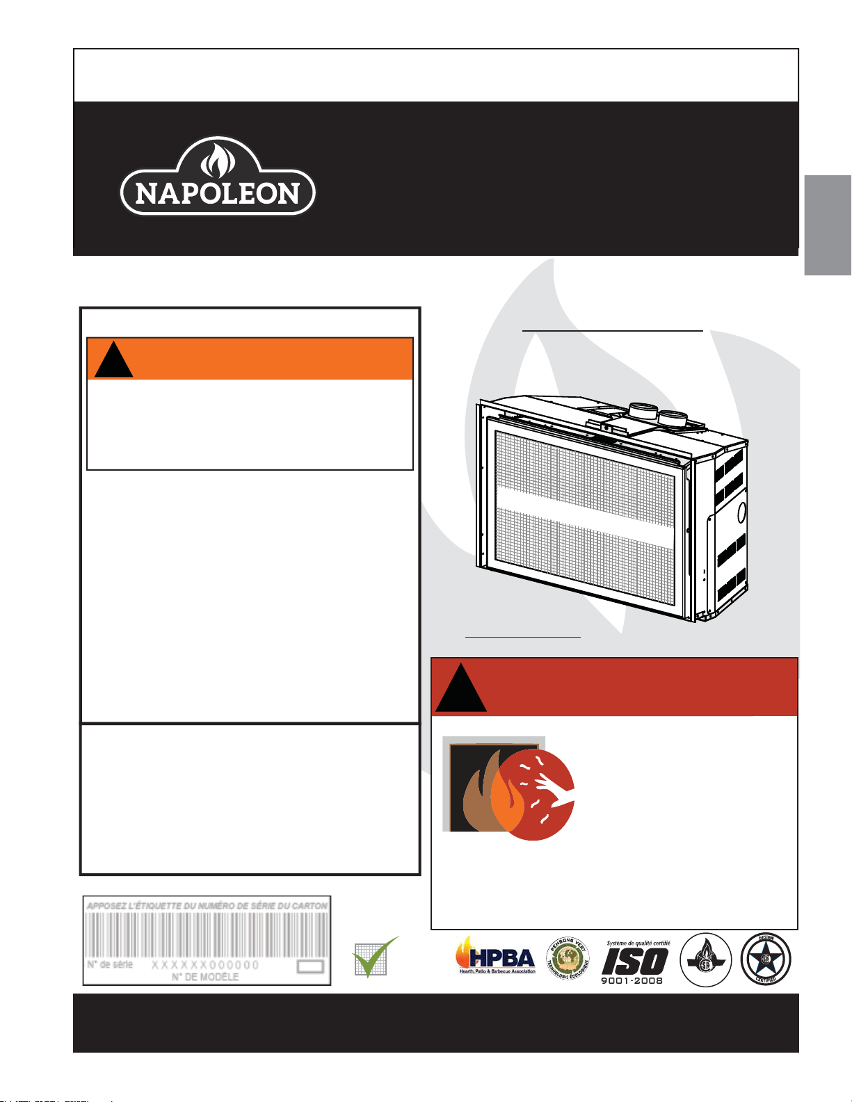
43
W415-1343 / A / 11.18.16
FR
INSTALLATEUR : LAISSEZ CE MANUEL AVEC L’APPAREIL.
PROPRIÉTAIRE : CONSERVEZ CE MANUEL POUR CONSULTATION ULTÉRIEURE.
NE LAISSEZ PAS LES ENFANTS OU AUTRES INDIVIDUS À RISQUE SEULS À PROXIMITÉ DE L’APPAREIL.
INSTRUCTIONS
D’INSTALLATION ET
D’OPÉRATION
Wolf Steel Ltd., 24 Napoleon Rd., Barrie, ON, L4M 0G8 Canada /
103 Miller Drive, Crittenden, Kentucky, USA, 41030
Téléphone 705-721-1212 • Télécopieur 705-720-9081 • www.napoleonfoyers.com • [email protected]
10,00$
CONSIGNES DE SÉCURITÉ
!
AVERTISSEMENT
- N’entreposez pas et n’utilisez pas d’essence ou autres
liquides et vapeurs inflammables à proximité de cet
appareil ou tout autre appareil.
- QUE FAIRE SI VOUS DÉTECTEZ UNE ODEUR DE GAZ :
• N’allumez aucun appareil.
• Ne touchez à aucun interrupteur électrique; n’utilisez
aucun téléphone dans votre immeuble.
• Appelez immédiatement votre fournisseur de gaz
d’un téléphone voisin. Suivez ses instructions.
• Si vous ne pouvez pas rejoindre votre fournisseur de
gaz, appelez le service des incendies.
- L’installation et l’entretien doivent être faits par un
installateur qualifié, une agence d’entretien ou le
fournisseur.
Cet appareil peut être installé dans une maison
préfabriquée (mobile) déjà installée à demeure si les
règlements locaux le permettent.
Cet appareil doit être utilisé uniquement avec le type
de gaz indiqué sur la plaque signalétique. Cet appareil
ne peut être converti à d’autres gaz, sauf si une
trousse de conversion est utilisée.
Si ces instructions ne sont pas suivies
à la lettre, un incendie ou une explosion
pourraient s’ensuivre, causant des
dommages matériels, des blessures
corporelles ou des pertes de vie.
LA VITRE CHAUDE CAUSERA
DES BRÛLURES.
NE PAS TOUCHER LA VITRE
AVANT QU’ELLE AIT REFROIDI.
NE JAMAIS LAISSER LES
ENFANTS TOUCHER LA VITRE.
!
AVERTISSEMENT
Une barriére conçu à réduire le risque de brûlures
causées par le verre chaud est fourni avec l’appareil
et sera installé pour la protection des enfants et
d’autres personnes à risque.
CERTIFIED
ÉCRAN DE
PROTECTION
ÉCRAN DE PROTECTION
CERTIFIÉ SELON LES NORMES NATIONALES CANADIENNES ET AMÉRICAINES: CSA 2.22 ET ANSI Z21.50 POUR LES APPAREILS À GAZ VENTILÉS.
XIR3N
GAZ NATUREL
XIR3P
PROPANE
AVERTISSEMENT: POUR USAGE INTÉRIEUR
SEULEMENT.

44
W415-1343 / A / 11.18.16
TABLE DES MATIÈRES
1.0 VUE D’ENSEMBLE DE L’INSTALLATION 45
2.0 INTRODUCTION 46
2.1 DIMENSIONS 47
2.2 DÉGAGEMENTS MINIMAUX AUX MATÉRIAUX COMBUSTIBLES 47
2.3 INSTRUCTIONS GÉNÉRALES 47
2.4 INFORMATION GÉNÉRALE 48
2.5 PLAQUE D'HOMOLOGATION 49
3.0 INSTALLATION 50
3.1 MISE À NIVEAU DE L'ENCASTRÉ 50
3.2 INSTALLATION DE LA CHEMINÉE 51
3.3 BRANCHEMENT DU GAZ 52
4.0 FINITIONS 53
4.1 DÉGAGEMENTS MINIMAUX DE LA TABLETTE 53
4.2 ENLÈVEMENT ET INSTALLATION DE LA PORTE 54
4.3 DISPOSITION DES BÛCHES 55
4.4 PLACEMENT DE LA ROCHES OPTIONNELLE 56
4.5 BRAISES INCANDESCENTES 56
4.6 MISE EN PLACE DU LOGO 56
4.7 INSTALLATION DES PILES 57
5.0 INFORMATION ÉLECTRIQUE 58
5.1 SCHÉMA DE CÂBLAGE 58
6.0 FONCTIONNEMENT 59
6.1 INSTRUCTIONS D'OPÉRATION ET D'ALLUMAGE 59
6.2 XIR3 FONCTIONNEMENT 60
6.2.1 DESSIN GÉNÉRAL DE LA TÉLÉCOMMANDE 60
6.2.2 FONCTIONNEMENT DE L’APPAREIL 60
6.2.3 FONCTIONEMENT DE LA TÉLÉCOMMANDE 60
6.2.4 AFFICHEUR DE TEMPÉRATURE 61
6.2.5 THERMOSTAT DE PIÈCE 61
6.2.6 THERMOSTAT SMART 61
6.2.7 HAUTEUR DE LA FLAMME 61
6.2.8 FONCTION DE SÉCURITÉ POUR ENFANTS 62
6.2.9 LUMIÈRE DE VEILLE 62
6.2.10 PILES FAIBLES / DÉRIVATION MANUELLE 62
6.2.11 EN CAS DE PANNE DE COURANT 62
6.2.12 MODULE DE CONTRÔLE 62
6.2.13 SOUPAPE À DÉBIT DIVISÉ 63
6.2.14 MINUTERIE DE SOUFFLERIE 63
6.3 L'INTERRUPTEUR ANTICONDENSATION 63
7.0 RÉGLAGES 64
7.1 RÉGLAGE DE LA VEILLEUSE 64
7.2 RÉGLAGE DU VENTURI 64
7.3 CARACTÉRISTIQUES DE LA FLAMME 65
8.0 ENTRETIEN 66
8.1 ENTRETIEN ANNUEL 67
8.2 SOINS DE LA VITRE 67
8.3 SOINS DES PIÈCES PLAQUÉES 68
8.4 REMPLACEMENT DE LA VITRE DE PORTE 68
8.5 ENLÈVEMENT DU BRÛLEUR 69
8.6 REMPLACEMENT DU MODULE SOUFFLEUR 70
8.7 REMPLACEMENT DE LA LUMIÈRES DE VEILLE 70
8.8 REPLACEMENT DE L'ASSEMBLAGE DE LA SOUPAPE 71
9.0 RECHANGES 72
10.0 VUE D'ENSEMBLE 73
10.1 VUE D'ENSEMBLE (P. 2) 74
10.2 L'ASSEMBLAGE DE LA SOUPAPE 75
10.3 L'ASSEMBLAGE DE LA CHAMBRE DE COMBUSTION 76
11.0 ACCESSOIRES 77
11.1 ACCESSOIRES (P.2) 78
12.0 GUIDE DE DÉPANNAGE 79
13.0 GARANTIE 82
14.0 HISTORIQUE D’ENTRETIEN 83
NOTE: L'icône du camera indique que les vidéos sont disponibles comme une référence supplémentaire,
visitez http://mynapoleon.napoleonproducts.com/download/index/44/1
FR
NOTE : Les changements autres que de nature éditoriale sont dénotés par une ligne verticale dans la
marge.
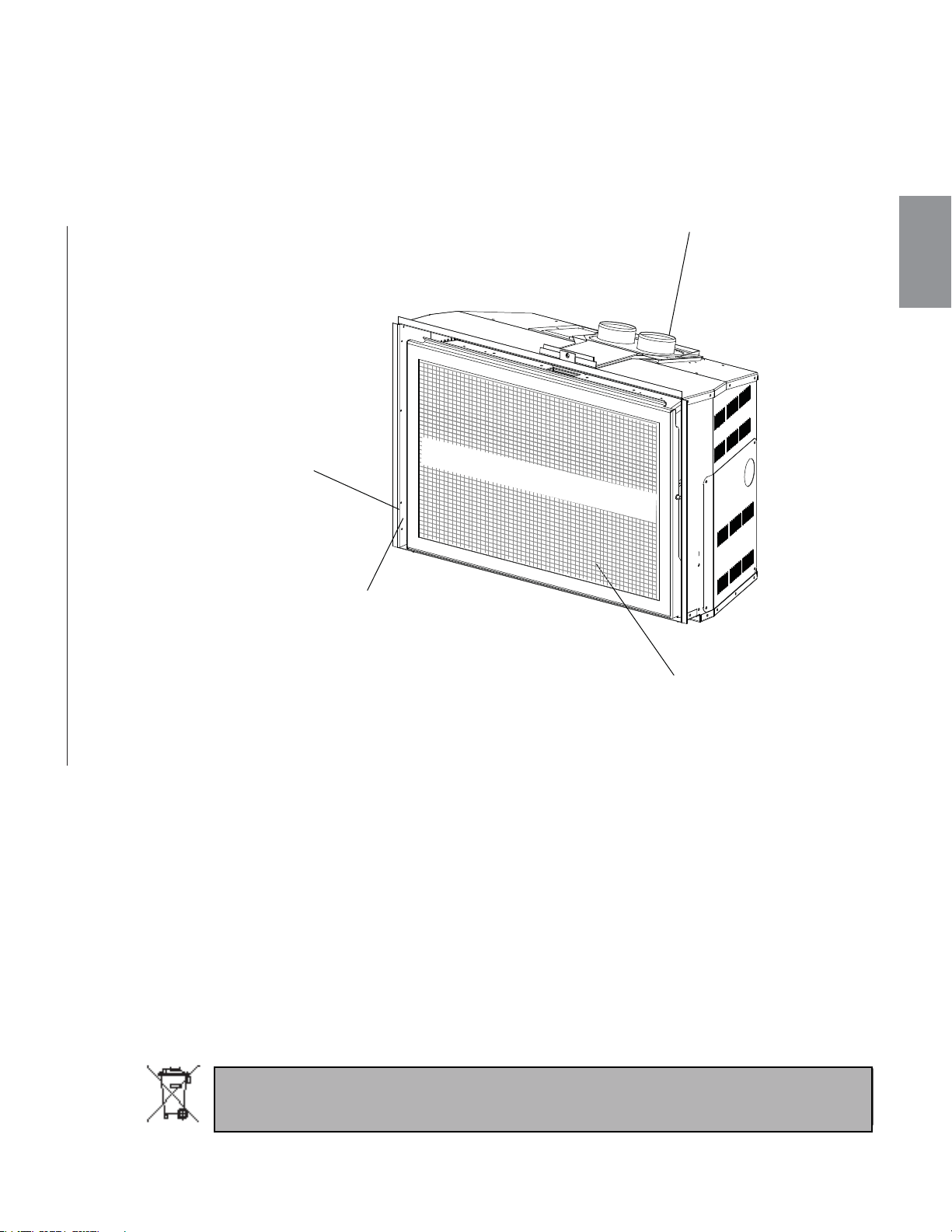
45
W415-1343 / A / 11.18.16
FR
Évacuation, voir la section
« INSTALLATION - INSTALLATION
DE LA CHEMINÉE ».
Plaque d’homologation,
voir la section
« INFORMATION SUR
LA PLAQUE
D’HOMOLOGATION ».
Bûches, voir la section
« FINITIONS - DISPOSITION
DES BÛCHES ».
Piles, voir la section
«INSTALLATION DES PILES.
Télécommande, voir la section,
"PROGRAMMATION"
ÉCRAN DE PROTECTION
1.0 VUE D’ENSEMBLE DE L’INSTALLATION
Les piles doivent être mises au rebut conformément aux lois et à la réglementation locales. Certaines piles
peuvent être recyclées dans votre centre de recyclage local. Renseignez-vous auprès de votre
municipalité au sujet des directives de recyclage.

46
W415-1343 / A / 11.18.16
FR
2.0 INTRODUCTION
3.2C
!
AVERTISSEMENT
• CET APPAREIL EST CHAUD LORSQU’IL FONCTIONNE ET PEUT CAUSER DE GRAVES BRÛLURES EN CAS DE CONTACT.
• TOUTE MODIFICATION APPORTÉE À CET APPAREIL OU AUX CONTRÔLES PEUT ÊTRE DANGEREUX ET EST INTERDIT.
• Ne faites pas fonctionner l’appareil avant d’avoir lu et compris les instructions d’opération. Omettre d’utiliser l’appareil selon les
instructions d’opération pourrait causer un incendie ou des blessures.
• Risque d’incendie ou d’asphyxie. Ne faites pas fonctionner l’appareil avec la vitre retirée.
• Ne branchez pas la soupape à du courant 110 volts.
• Risque de brûlures. L’appareil doit être éteint et refroidi avant d’effectuer un entretien.
• N’installez pas de composants endommagés ou incomplets ni des composants substituts.
• Risque de coupures et d’érafl ures. Portez des gants protecteurs et des lunettes de sécurité lors de l’installation. Les bordures
des pièces de métal peuvent être coupantes.
• Ne brûlez pas de bois ou autres matériaux dans cet appareil.
• Les enfants et les adultes devraient être informés des dangers que posent les températures de surface élevées et se
tenir à distance afin d’éviter des brûlures ou que leurs vêtements ne s’enflamment.
• Les jeunes enfants doivent être surveillés attentivement lorsqu’ils sont dans la même pièce que l’appareil. Les
jeunes enfants et autres personnes à risque sont sujets aux brûlures accidentelles. Une barrière de protection est
recommandée si des individus à risque se trouvent dans la maison. Afi n de restreindre l’accès à l’appareil, installez une
barrière de protection ajustable pour garder les jeunes enfants ou autres personnes à risque hors de la pièce et loin des
surfaces chaudes.
• Les vêtements et autres matériaux combustibles ne doivent pas être posés sur l’appareil ou à proximité.
• En raison des températures élevées, l’appareil devrait être placé loin des endroits passants et loin des meubles et des
rideaux.
• Assurez-vous de disposer de mesures de sécurité adéquates pour empêcher les jeunes enfants de toucher aux surfaces
chaudes.
• Même une fois que l’appareil est éteint, la vitre et/ou le pare-étincelles demeureront chauds pendant un temps prolongé.
• Consultez votre détaillant local de foyer pour connaître les grillages de sécurité et les écrans offerts pour protéger les enfants
des surfaces chaudes. Ces grillages de sécurité et ces écrans doivent être fi xés au plancher.
• Tout grillages de sécurité, écrans ou barriére enlevés pour faire l’entretien devront être remis en place avant d’utiliser l’appareil.
• Cet appareil est un appareil à gaz ventilé. Ne brûlez pas de bois ou autres matériaux dans cet appareil.
• Il est primordial de garder propres les compartiments de contrôle, les brûleurs, la souffl erie, les bouches d’air de l’appareil ainsi
que le système d’évacuation. L’appareil et son système d’évacuation doivent être inspectés avant la première utilisation et au
moins une fois l’an par un spécialiste en entretien. Un entretien plus fréquent pourrait être nécessaire en raison des peluches
provenant des tapis, literie, etc. L’emplacement de l’appareil doit être gardé libre de tous matériaux combustibles, essence ou
autres liquides et vapeurs infl ammables.
• Cet appareil ne devra être modifi é en aucun cas.
• Cet appareil ne doit pas être raccordé au conduit d’une cheminée desservant un autre appareil de chauffage à combustible solide.
• N’utilisez pas cet appareil si une partie quelconque a été submergée. Contactez immédiatement un technicien de service qualifi é
pour inspecter l’appareil et pour remplacer toute pièce du système de contrôle et du contrôle du gaz qui aurait été submergée.
• Ne pas opérer l’appareil lorsque la porte vitrée est enlevée, fi ssurée ou brisée. Le remplacement de la vitre devra être effectué
par un technicien de service certifi é ou qualifi é.
• Ne frappez pas et ne claquez pas la porte vitrée de l’appareil.
• Les portes d’évacuation de pression doivent demeurer fermées pendant le fonctionnement de l’appareil afi n d’empêcher les
gaz de combustion contenant du monoxyde de carbone de s’infi ltrer dans la maison. La température des gaz de combustion
s’échappant par ces ouvertures peut aussi causer les matériaux combustibles avoisinants à surchauffer et à prendre feu.
• Seules les portes/façades certifi ées pour cet appareil peuvent être utilisées avec cet appareil.
• Gardez les matériaux d’emballage hors de la portée des enfants et mettez ces matériaux au rebut de façon sécuritaire. Comme
tous les emballages de plastique, ces matériaux ne sont pas des jouets et doivent demeurer hors de la portée des enfants et des
bébés.
• Comme dans le cas de tout appareil à combustion, il est recommandé de faire inspecter et entretenir votre appareil
régulièrement. De même, installez un détecteur de monoxyde de carbone dans la pièce pour vous protéger, ainsi que votre
famille, contre les intoxications.
• Assurez-vous de respecter les dégagements aux matériaux combustibles lorsque vous installez un manteau ou des tablettes
au-dessus de l’appareil. Les températures élevées sur le mur ou de l’air au-dessus de l’appareil peuvent faire fondre, décolorer
ou endommager les décorations, les téléviseurs ou autres composants électroniques.
• Une barriére conçu à réduire le risque de brûlures causées par le verre chaud est fourni avec l’appareil et sera installé.
• Si la barriére est endommagée, elle devra être remplacée par la barriére conçu par le manufacturier pour cet appareil.
• L’installation et la réparation devraient être effectuées par un technicien qualifi é. L’appareil et son système d’évacuation
devraient être inspectés avant l’utilisation initiale et au moins une fois l’an par un professionel qualifi é. Un nettoyage
plus réquent peut être requis en raison de la poussière excessive laissée par les moquettes, les couvertures, etc. Il est
impératif que les compartiments de contrôle, le brûleur et les passages de circulation d’air soient gardés propres afi n de
fourni une combustion et une circulation d’air adéquates.
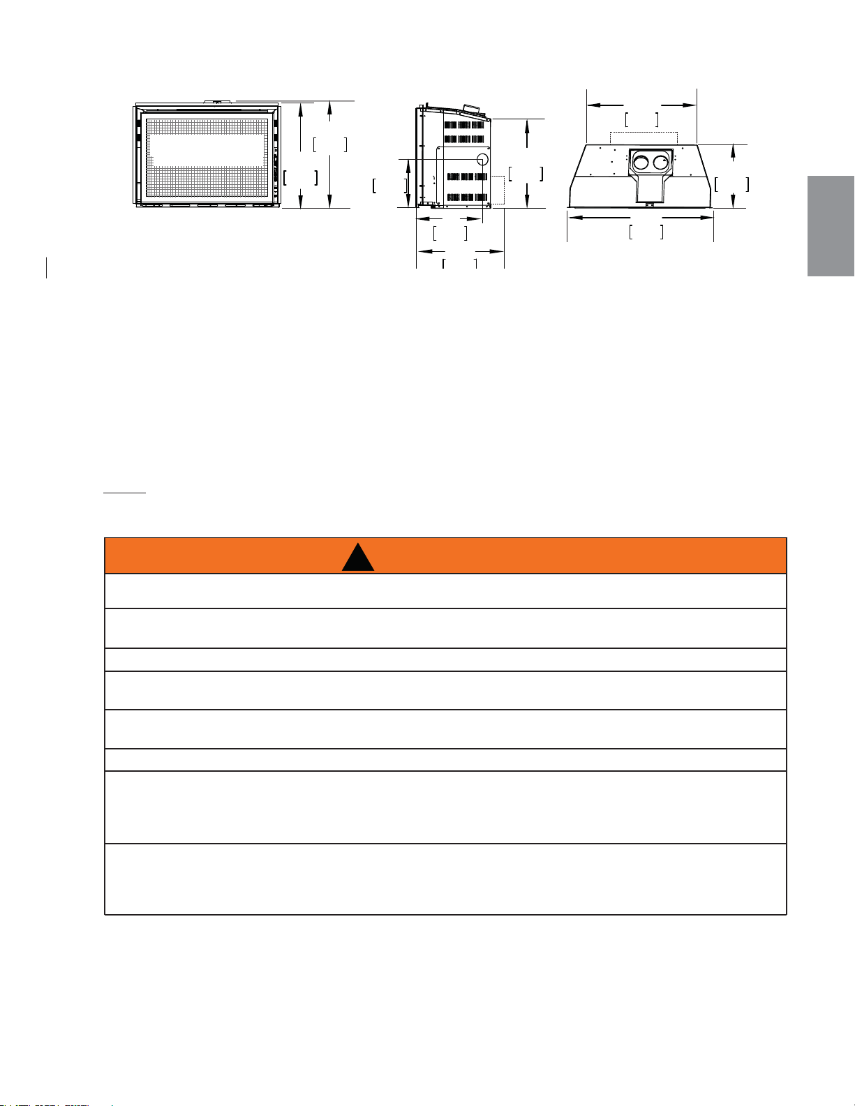
47
W415-1343 / A / 11.18.16
FR
2.1 DIMENSIONS
CET APPAREIL AU GAZ DEVRAIT ÊTRE INSTALLÉ ET ENTRETENU PAR UN INSTALLATEUR QUALIFIÉ en se conformant
aux codes locaux. Les pratiques d’installation peuvent varier d’une région à l’autre. Il est donc important de connaître les normes
spécifi ques qui s’appliquent à votre région. Par exemple dans l’état du Massachusetts:
• Ce produit doit être installé par un plombier certifi é ou un installateur pour le gaz lorsque installé dans le Commonwealth du
Massachusetts.
• Le registre de l’appareil doit être enlevé ou bloqué en le soudant en position ouverte avant d’installer un encastré ou un ensemble
de bûches à gaz.
• La soupape d’arrêt doit être un robinet à gaz avec une poignée en T.
• Le raccord fl exible ne doit
p
as mesurer
p
lus
q
ue 36
p
ouces
(
914.4mm
)
.
!
AVERTISSEMENT
ALLUMEZ TOUJOURS LA VEILLEUSE, QUE CE SOIT POUR LA PREMIÈRE FOIS OU LORSQUE
L’APPROVISIONNEMENT EN GAZ EST ÉPUISÉ, AVEC LA PORTE VITRÉE OUVERTE OU RETIRÉE.
PRÉVOYEZ UN ACCÈS SUFFISANT POUR ENTRETENIR ET OPÉRER L’APPAREIL.
ASSUREZ-VOUS D'UNE QUANTITÉ SUFFISANTE D’AIR DE VENTILATION.
N’OBSTRUEZ JAMAIS L’OUVERTURE DE L’APPAREIL.
LES OBJETS PLACÉS DEVANT L’APPAREIL DOIVENT ÊTRE GARDÉS À UNE DISTANCE D'AU MOINS 48"
(1219.2mm) DE LA FACE VITRÉE DE L'APPAREIL.
LES SURFACES AUTOUR ET SURTOUT AU-DESSUS DE L’APPAREIL PEUVENT DEVENIR CHAUDES.
NE TOUCHEZ PAS L’APPAREIL QUAND IL FONCTIONNE.
RISQUE D’INCENDIE OU D’EXPLOSION.
LES PRESSIONS ÉLEVÉES ENDOMMAGERONT LA SOUPAPE. L’ALIMENTATION EN GAZ DOIT ÊTRE DÉBRANCHÉE
PENDANT LES ESSAIS DE PRESSION DE CE SYSTÈME LORSQUE LES PRESSIONS D’ESSAI EXCÈDENT ½ LB/PO²
(3,5 KPA). FERMEZ LA SOUPAPE D’ARRÊT MANUELLE PENDANT TOUT ESSAI DE PRESSION DU SYSTÈME
D’ALIMENTATION EN GAZ LORSQUE LA PRESSION EST DE ½ LB/PO² (3,5 mb) OU MOINS.
N’UTILISEZ QUE LES ACCESSOIRES OPTIONNELS ET LES PIÈCES DE RECHANGE APPROUVÉS PAR WOLF
STEEL POUR CET APPAREIL. L’UTILISATION D’ACCESSOIRES NON LISTÉS (SOUFFLERIE, PORTES,
PER-SIENNES, MOULURES, COMPOSANTS DE GAZ, COMPOSANTS D’ÉVACUATION, ETC.) POURRAIT ÊTRE
NON SÉCURITAIRE ET ANNULERA LA GARANTIE ET LA CERTIFICATION..
Cet appareil ne doit être encastré que dans un foyer à bois ventilé incombustible (préfabriqué ou en maçonnerie).
L'appareil dans lequel l’encastré est installé doit avoir les dimensions minimales suivantes :
HAUTEUR 21
1
/
2
" (54,6cm) LARGEUR 29"(73,6cm) LARGEUR *13
1
/
2
" (34,3cm)
Le diamètre minimal du conduit de la cheminée doit être de 7"(178mm) rond.
* Ajoutez 4" (102mm) pour la souffl erie optionnelle.
La distance minimale entre le dessous d’une tablette décorative combustible qui ressort un maximum de 3"
(76mm) et le haut de l'ouverture des persiennes est de 14" (35,6cm) (voir la section DÉGAGEMENTS MINIMAUX
DE LA TABLETTE).
NOTE: LE FOYER INCOMBUSTIBLE DOIT DÉPASSER UNE MINIMUM DE 12" (305mm) DE L'APPAREIL.
2.2 DÉGAGEMENTS MINIMAUX AUX MATÉRIAUX COMBUSTIBLES
21"
533mm
20 1/2"
521mm
12"
305mm
17 1/2"
445mm
9 1/2"
241mm
17 1/2"
445mm
29 5/8"
753mm
22 7/8"
581mm
13 1/4"
337mm
SAFETY BARRIER
2.3 INSTRUCTIONS GÉNÉRALES
ÉCRAN DE PROTECTION
*
* DIMENSION REQUIS AVEC LA SOUFFLERIE OPTIONNEL INSTALLÉ.
48
W415-1343 / A / 11.18.16
FR
2.4 INFORMATION GÉNÉRALE
4.12A
• Un détecteur de monoxyde de carbone est requis dans toutes les pièces contenant des appareils alimentés au gaz.
• L’appareil n’est pas approuvé pour installation dans une chambre à coucher ou une salle de bain à moins d’être un appareil avec
une chambre de combustion scellée à évacuation directe.
L’installation doit se conformer aux codes locaux. En l’absence de codes locaux, l’installation doit être conforme au Code
d’installation du gaz naturel et du propane CSA B149.1 au Canada ou au National Fuel Gas Code, ANSI Z223.1/ NFPA 54 aux
États-Unis. Cet appareil convient pour installation dans une maison mobile
si l’installation est conforme aux normes actuelles pour les maisons
mobiles équipées au gaz CAN/CSA Z240 SÉRIE MM au Canada ou selon
les normes ANSI Z223.1 et NFPA 54 aux États-Unis.
Certains appareils ont une souffl erie ou un ensemble de deux
souffl eries optionnel. Si la souffl erie ou l’ensemble de deux souffl eries
optionnel est installé, la boîte de dérivation doit être branchée au circuit
électrique et mise à la terre conformément aux codes locaux. Utilisez la
version courante du Code canadien de l’électricité CSA C22.1 au Canada
ou le National Electrical Code ANSI/NFPA 70 aux États-Unis.
Nous suggérons que nos
appareils au gaz soient installés
et que l'entretien soit effectué
par des professionnels certi-
fiés par le National Fireplace
Institute® (NFI) comme
spécialiste du gaz NFI.
POUR VOTRE SATISFACTION, CE FOYER A ÉTÉ MIS À L’ESSAI POUR CONFIRMER SON
FONCTIONNEMENT ET SA QUALITÉ!
XIR3
NG P
Altitude (PI) 0-4,500 0-4,500
Débit maximum (BTU/HR) 31,000 31,000
Rend. max. (BTU/HR) 24,800 24,800
Efficacité (avec ventilateur en
marche)
80% 80%
A.F.U.E. (valeur maximale) 77% 77%
Pression minimale d'alimentation
en gaz
4,5" de colonne d’eau (11mb) 11" de colonne d’eau (27mb)
Pression maximale d'alimentation
en gaz
13" de colonne d’eau (32mb) 13" de colonne d’eau (32mb)
Pression du collecteur (lorsque le
gaz circule)
3,5"de colonne d’eau (9mb) 10"de colonne d’eau (25mb)
Lorsque l'appareil est installé à des élévations dépassant 4 500 pieds (1371m), et en l’absence de
recommandations spécifiques de l’autorité compétente locale, l’indice certifié du débit à haute altitude
devra être réduit au taux de 4 % pour chaque 1 000 pieds (305m) supplémentaires. Les bruits causés par
l’expansion et la contraction lors des cycles de chauffage et de refroidissement sont tout à fait normaux et il
faut s’y attendre.
Cet appareil n’est pas approuvé pour installation dans un placard ou en retrait. Il est approuvé pour
installation dans les salles de bain, les chambres à coucher et les chambres studio et convient pour
installation dans les maisons mobiles. Le modèle au gaz naturel ne peut être placé que dans une maison
mobile installée en permanence et alimentée au gaz naturel.
Une barrière conçu à réduire le risque de brûlures à partir de le chaude la vitre est à condition que
avec l’appareil et sera être installés.
67,0 %
XIR3
Cote énergétique des foyers à gaz
Basée sur la norme CSA P.4.1-02
Modèle no
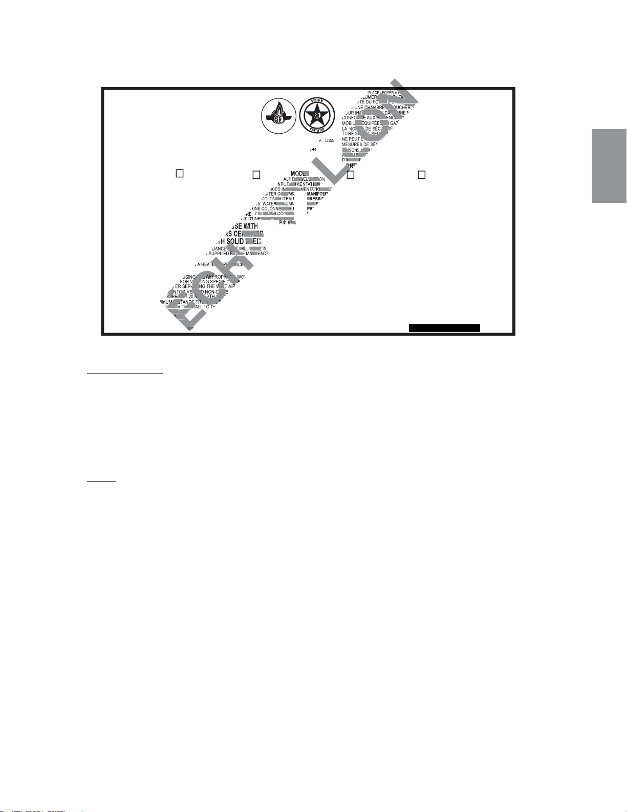
49
W415-1343 / A / 11.18.16
FR
2.5 PLAQUE D'HOMOLOGATION
INSTALLATEUR : Il est de votre responsabilité de cocher les cases appropriées sur la plaque
d'homologation correspondant au modèle, au type d'évacuation et au type de gaz de l'appareil.
Pour l’emplacement de la plaque d’homologation, voir la section « VUE D’ENSEMBLE DE L’INSTALLATION ».
Cette illustration est à titre de référence seulement. Consultez la plaque d’homologation pour obtenir
l’information précise.
NOTE: La plaque d'homologation doit toujours rester avec l'appareil. Il ne doit pas être enlever.
SERIAL NUMBER/NO. DE SERIE:
XIR3/CXIR3
AVERTISSEMENT:
N'A JOUTEZ PAS A CET APPAREIL AUCUN MATERIAU DEVANT
ENTRER EN CONTACT AVEC LES FLAMMES AUTR
E QUE CELUI QUI EST FOURNI AVEC CET
APPAREIL PAR LE FABRICANT.
PRODUIT DÉCORATIF: NE PAS UTILSER COMME APPAREIL DE CHAUFFAGE.
W385-1972 / A
ROF DEI
F
I
T
REC
RU
OP EEIFIT
RE
C
ASU
ADANAC
XIR3N XIR3PCXIR3N
CXIR3P
MODEL
CERTIFIED
647
161
#
ECNEREFER
CONFORMS TO / CONFORME AUX: ANSI Z21.50-2014, CERTIFIED TO / CERTIFIE CSA 2.22-2014 VENTED GAS FIREPLACE / FOYER À GAZ VENTILÉ.
WOLF STEEL LTD.
24 NAPOLEON ROAD, BARRIE. ONTARIO L4M 0G8 CANADA
ELECTRICAL RATING:
115V 1.5AMP 60HZ
THE APPLIANCE MUST BE VENTED USING THE APPROPRIATE WOLF STEEL VENT KITS. SEE
OWNER’S INSTALLATION MANUAL FOR VENTING SPECIFICS. PROPER REINSTALLATION AND
RESEALING IS NECESSARY AFTER SERVICING THE VENT-AIR INTAKE SYSTEM.
WARNING:
FOR INSTALLATION INTO A VENTED NON-COMBUSTIBLE FIREPLACE ONLY. THE
MINIMUM FIREPLACE SIZE IS: HEIGHT 20.5”, DEPTH 13.5”, WIDTH 29”. THE MINIMUM INSIDE
FLUE SIZE IS 7”. THE MINIMUM DISTANCE FROM THE BOTTOM OF A COMBUSTIBLE MANTEL
PROJECTING A MAXIMUM 3” FROM THE WALL TO THE TOP OF THE UNIT IS 14”. SEE OWNER’S
MANUAL FOR GREATER EXTENSIONS.
OPTIONAL FAN KIT - GZ550-KT, GD65.
CLASS :
115V, 1.5AMP, 60HZ
L’APPAREIL DOIT EVACUER SES GAZ EN UTILISANT L’ENSEMBLE D’EVACUATION PROPRE A WOLF STEEL.
REFERER AU MANUEL D’INSTALLATION DE PROPRIETAIRE POUR L’EVACUATION PRECISE. IL EST IMPORTANT DE
BIEN REINSTALLER ET RESCELLER L’EVENT APRES AVOIR ASSURE LE MAINTIEN DU SYSTEME DE PRISE D’AIR.
ATTENTION :
POUR INSTALLATION DANS UN FOYER VENTILE EN MACONNERIE. LES DIMENSIONS MINIMUMS
SONT: HAUTER 21.5”, PROFONDEUR 13.5”, LARGEUR 29”. LE DIAMETRE INTERIEUR MINIMUM DE CONDUIT
D’EVACUATION EST DE 7”. LA DISTANCE MINIMALE, DU BAS DU MANTEAU COMBUSTIBLE FORMANT UNE
PROJECTION MAXIMALE DE 3” DU MUR AU DESSUS DE LA GARNITURE NORMALE EST 14”. REFERER AU MANUEL
D’INSTALLATION POUR DES EXTENSIONS PLUS GRANDES.
SOUFFLERIE OPTIONELLE
GZ550-KT, GD65.
4500FT (0-1370m) ALTITUDE/ELEVATION 4500FT (0-1370m)
h/UTB 000,13 NOITATNEMILA/TUPNI h/UTB 000,13
11,000 BTU/h REDUCED INPUT/ALIMENTATION REDUITE 16,000 BTU/h
MANIFOLD PRESSURE: 3.5” WATER COLUMN
PRESSION AU COLLECTEUR: 3.5” D’UNE COLONNE D’EAU
MINIMUM SUPPLY PRESSURE: 4.5” WATER COLUMN
PRESSION D’ALIMENTATION MINIMALE: 4.5” D’UNE COLONNE D’EAU
MAXIMUM SUPPLY PRESSURE:
7.0” WATER COLUMN
PERSSION D’ALIMENTATION MAXIMALE:
7.0” D’UNE COLONNE D’EAU
MANIFOLD PRESSURE: 10” WATER COLUMN
PRESSION AU COLLECTEUR: 10” D’UNE COLONNE D’EAU
MINIMUM SUPPLY PRESSURE: 11” WATER COLUMN
PRESSION D’ALIMENTATION MINIMALE: 11” D’UNE COLONNE D’EAU
MAXIMUM SUPPLY PRESSURE: 13” WATER COLUMN
PERSSION D’ALIMENTATION MAXIMALE: 13” D’UNE COLONNE D’EAU
THIS VENTED GAS FIREPLACE IS NOT FOR USE WITH
AIR FILTERS. FOR USE WITH GLASS DOORS CERTIFIED
FOR THIS UNIT ONLY. NOT FOR USE WITH SOLID FUEL.
CE FOYER À GAZ VENTILÉS NE DOIT PAS ÊTRE UTILISÉ
CONJOINTEMENT AVEC DES FILTRES À AIR. UTILISER AVEC LES
PORTES VITRÉES HOMOLOGUÉES AVEC CETTE UNITÉ SEULE-
MENT. UN COMBUSTIBLE SOLIDE NE DOIT PAS ETRE UTILISE
AVEC CET APPAREIL.
NE PAS ALLUMER SI DES ENFANTS OU D’AUTRES INDIVIDUS À RISQUE
SONT À
PROXIMITÉ DU FOYER. FOYER À GAZ VENTILÉ HOMOLOGUÉ POUR INSTALLATION
DANS UNE CHAMBRE À COUCHER, UNE SALLE DE BAIN ET UN STUDIO. APPROPRIÉ
POUR INSTALLATION DANS UNE MAISON MOBILE SI SON INSTALLATION EST
CONFORME AUX EXIGENCES DE LA NORME CAN/CSA Z240MH SÉRIE DE MAISONS
MOBILES ÉQUIPÉES AU GAZ, EN VIGUEUR AU CANADA, OU AUX ÉTATS-UNIS, SELON
LA NORME DE SÉCURITÉ ET DE CONSTRUCTION DE MAISONS MANUFACTURÉES,
TITRE 24 CFR, SECTION 3280. DANS LE CAS OÙ CETTE NORME DES ÉTATS-UNIS
NE PEUT ÊTRE APPLIQUÉE, SE RÉFÉRER À LA NORME RELATIVE AU CRITÈRE DE
MESURES DE SÉCURITÉ CONTRE L'INCENDIE POUR LES INSTALLATIONS DANS LES
MAISONS MANUFACTURÉES, LES SITES ET LES COMMUNAUTÉS, ANSI/NFPA 501A.
POUR UNE UTILISER AVEC BARRIÈRE W565-0133. SUIVEZ LES INSTRUCTIONS
D'INSTALLATION SE TROUVENT DANS LE MANUEL D'INSTALLATION
.
DO NOT TURN ON IF CHILDREN OR OTHER AT RISK INDIVIDUALS
ARE NEAR THE FIREPLACE. DIRECT VENT GAS FIREPLACE.
SUITABLE FOR BEDROOM, BATHROOM AND BED-SITTING
ROOM INSTALLATION. SUITABLE FOR MOBILE HOME INSTALLATION
IF INSTALLED IN ACCORDANCE WITH THE CURRENT STANDARD
CAN/CSA Z240MH SERIES GAS EQUIPPED MOBILE HOMES, IN
CANADA OR IN THE UNITED STATES THE MANUFACTURED HOME
CONTRUCTION AND SAFETY STANDARD, TITLE 24 CFR, PART 3280.
WHEN THIS US STANDARD IS NOT APPLICABLE USE THE
STANDARD FOR FIRE SAFETY CRITERIA FOR MANUFACTURED
HOME INSTALLATIONS, SITES AND COMMUNITIES, ANSI / NFPA
501A
.
FOR USE WITH BARRIER W565-0133. FOLLOW THE INSTALLATION
INSTRUCTIONS LOCATED IN THE INSTALLATION MANUA
L.
WARNING:
DO NOT ADD ANY MATERIAL TO THE APPLIANCE THAT WILL COME IN
CONTACT WITH THE FLAMES, OTHER THAN THAT SUPPLIED BY THE MANUFACTURER
WITH THE APPLIANCE.
DECORATIVE PRODUCT: NOT FOR USE AS A HEATING APPLIANCE
P.4: 67%
P.4: 67%
NATURAL GAS / GAZ MODEL
PROPANE MODEL
N
ÉCHANTILLON
A
L
ODEL
N
E / FOYER À GAZ VEN
ARIO
G
THE
APPROPRI
A
TE W
A
VENTING SPECIFICS. PR
FT
VICI
VEN
T
R
N I
O
A
VENTED NON-COM
A
S: HEIGH
T
20.5”, DEPTH 13.5”
T
M DIS
T
CE FROM
THE B
” FRO
THE
W
A
W
ENSIONS.
GD65.
TUDE/ELE
VA
TIO
A
N
O
I
T
M
I
L
A
/
T
NPUT/ALIM
ON RED
COLUMN
NNE D
R COLU
E D’EAU
0”
W
A
W
TER COLUMN
A
E COLONNE D’EAU
OLD
PR
MINI
PRE
WIT
RTIFIED
SOLID FUEL.
R SI DES EN
F
ANTS O
F
OYER.
FOYER À GAZ V
CHAMBRE À COUCHER, U
NS
T
ALL
T
A
TION DANS UN
A
ORME
X EXIGENCES D
ES ÉQUIPÉES
AU GAZ
RME DE SÉCURIT
24 CFR, SECTION
ÊTRE
APPLIQ
MESURES DE SÉ
MAISONS MANU
POUR UNE UT
INSTALLA
E
THAT
L
COME
I
B
Y
THE MANU
F
TING APPLIANCE
P4:
67%
PRO
50
W415-1343 / A / 11.18.16
FR
3.0 INSTALLATION
3.1 MISE À NIVEAU DE L'ENCASTRÉ
68.4B
Retirez les cendres de l’appareil de chauffage au bois. Assurez-vous que la cheminée et l’appareil de
chauffage au bois sont propres et en bon état et qu’ils sont construits avec des matériaux incombustibles.
Si nécessaire, faites faire les travaux de réparation par une personne qualifi ée avant d’installer l’encastré.
Enlevez le registre de l’appareil de chauffage au bois ou
fi xez-le en position ouverte.
À l’aide de vis, fi xez l’étiquette d’avertissement à
l’intérieur de la chambre de combustion de l’appareil
existant, dans lequel l’encastré sera installé.
Les composants en tôle de l’appareil existant, dans
lequel l’encastré sera installé, ne doivent pas être
sectionnés.
Si l’appareil de chauffage au bois ne possède pas de trou
d’accès pour le raccordement au gaz, un trou d’accès de 1 1/2” (38,1mm) ou moins peut être pratiqué selon
les règles du métier à travers les côtés inférieurs ou le plancher de l’appareil. Ce trou d’accès doit être bourré
d’isolant incombustible une fois que le tuyau d’alimentation en gaz a été installé.
Assurez-vous que la porte de la trappe de ramonage existante soit bien fermée.
Les briques réfractaires, la porte vitrée, la glissière, le rideau pare-étincelles et les supports à bûches peuvent
être retirés de l’appareil existant avant d’installer l’encastré.
Les tablettes de fumée, les écrans et les défl ecteurs peuvent être retirés s’ils sont fi xés avec des attaches
mécaniques.
Les ouvertures de ventilation de l’appareil peuvent être obstruées par les plaques de fond, les moulures en
aluminium, etc., mais ces composants ne doivent pas être installés de façon à sceller hermétiquement les
ouvertures.
!
AVERTISSEMENT
RISQUE D’INCENDIE CONSERVEZ LES DÉGAGEMENTS NÉCESSAIRES
AU CONDUIT D’EVENT ET À L’APPAREIL.
W385-0199_B
WARNING: THIS FIREPLACE HAS BEEN CONVERTED FOR USE WITH A GAS FIREPLACE
INSERT ONLY AND CANNOT BE USED FOR BURNING WOOD OR SOLID FUELS UNLESS ALL ORIGINAL
PARTS HAVE BEEN REPLACED AND THE FIREPLACE IS RE-APPROVED BY THE AUTHORITY HAVING
JURISDICTION.
ATTENTION: CE FOYER A ETE CONVERTI AFIN D’ETRE UTILISE SEULEMENT
COMME FOYER ENCASTRE AU GAZ ET NE PEUT ETRE UTILSE POUR BRULER DU BOIS OU
TOUT AUTRE COMBUSTIBLE SOLIDE, SANS QUE TOUTES LES PIECES ORIGINALES AIENT
ETE REMPLACEES ET QUE LE FOYER SOIT APPROUVE DE NOUVEAU PAR LES AUTORITES
AYANT JURIDICTION.
ADVERTENCIA: ESTA CHIMENEA SE REMODELÓ PARA USARSE SOLO CON UNA
INSERCIÓN DE CHIMENEA A GAS Y NO PUEDE USARSE PARA QUEMAR MADERA NI COMBUSTIBLES
SÓLIDOS, A MENOS QUE SE HAYAN REEMPLAZADO TODAS LAS PIEZAS ORIGINALES, Y LA AUTORI-
DAD JURISDICCIONAL LA HAYA VUELTO A APROBAR.
Placez l’encastré le plus près possible de son emplacement défi nitif. Cet appareil est muni de vis de réglage
situées sur la base. Mettez à niveau, en vous servant des vis de réglage, afi n d’éliminer les balancements et
le bruit excessif lorsque la souffl erie est en marche. Une fois que l’appareil est à niveau, ne le mettez que
partiellement en place afi n d’effectuer tous les raccordements. Il est diffi cile de mettre à niveau l’encastré
une fois qu’il est installé. Déterminez la profondeur requise avant d’installer l’appareil, puis ajustez les vis de
réglage en conséquence.
67.2
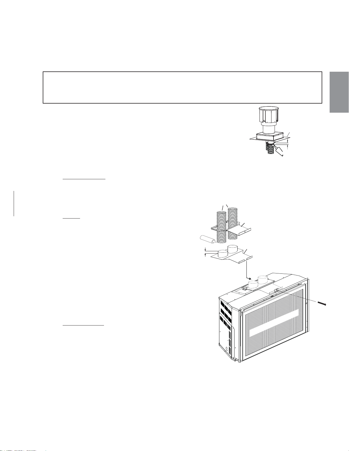
51
W415-1343 / A / 11.18.16
FR
Bien que les gaines doivent être continues de l'appareil au chapeau de la
cheminée, elles peuvent être raccordées pour obtenir la longueur désirée
en utilisant une bague d’accouplement approuvée. Nous recommandons
que la gaine d’évacuation qui traverse une zone non chauffée telle que des
cheminées extérieures de grande taille soit enveloppée dans un manchon
isolant, ceci afin d’éviter la condensation et les effets de refoulement. Pour
plus de détails, consultez la section « GUIDE DE DÉPANNAGE ». Cet appareil
est approuvé pour installation avec une gaine de 3"(76mm) de diamètre pour la
prise d’air et pour l’évacuation.
A. À L'EXTÉRIEUR : Faites glisser l'extrémité d’une gaine un minimum
de 2"
(51mm)
par-dessus le manchon
de la terminaison. Fixez à l'aide de 3
vis. Puis sceller les joint et vis avec
scellant à haute température. Répéter
avec l’autre gaine.
NOTE : Nous recommandons
que l'autre extrémité de la gaine
d'évacuation soit identifi ée pour
éviter qu'elle ne soit raccordée au
collet de prise d'air de l'appareil.
B. Étirez doucement les gaines
jusqu’aux longueurs désirées et
insérez-les dans la cheminée.
Découpez et placez la plaque de
raccord afi n qu’elle s’adapte au
chapeau de la cheminée. Placez la
terminaison par-dessus la cheminée.
Rendez-la étanche en la scellant avec
du calfeutrage (non fourni). Fixez
à la cheminée avec des vis et des
chevilles (non fournies).
C. À L'INTÉRIEUR : Retirez la vis de
fi xation du devant de la plaque
de support des évents. Engagez
seulement la plaque de support des
évents dans la glissière et tirez-la
jusqu’au support de fi xation à l’avant.
Installez la plaque coulissante de
la même façon. Réinstallez la vis
de fi xation. Vous pouvez à présent installer l’encastré dans son emplacement défi nitif à l’intérieur
de l'appareil de chauffage au bois, avec la vis de fi xation bien serrée de façon à ce que la plaque
coulissante soit solidement fi xée au support de fi xation.
D. Faites passer les gaines fl exibles à travers la plaque coulissante. Fixez les gaines à la plaque de
support des évents en suivant la même procédure qu'auparavant, en vous assurant que la gaine
d'évacuation identifi ée soit fi xée au collet d'évacuation.
PLAQUE DE
RACCORD
CHEVAUCHEMENT
DE 2” (50,8mm)
SCELLANT
À HAUTE
TEMPÉRATURE
PRISE D’AIR
ÉVACUATION
VIS DE
FIXATION
PLAQUE COULISSANTE
PLAQUE DE
SUPPORT
SCELLANT À
HAUTE TEMPÉRATURE
CHEVAUCHEMENT
DE 2" (50,8mm)
GAINE DE 3" (76,2mm)
ÉVACUATION
PRISE D’AIR
ÉCRAN DE PROTECTION
3.2 INSTALLATION DE LA CHEMINÉE
L’installation de la cheminée doit être conforme aux normes des codes nationaux et locaux. La cheminée
doit être munie d'un conduit de 2" (51mm) ou 3" (76mm) de diamètre pour la prise d'air et d'un conduit de 3"
(76mm) de diamètre pour l'évacuation. Les longueurs minimales et maximales des gaines sont respectivement
de 10' (3m) et 35' (11m). Les ensembles d’évents Napoléon recommandés sont offerts en trois longueurs :
2 GAINES DE 3" (76mm) EN ALUMINIUM À DOUBLE PAROI - PRISE D'AIR ET
ÉVACUATION:
GDI-320KT ENSEMBLE D'ÉVENTS 20 PI
GDI-325KT ENSEMBLE D'ÉVENTS 25 PI
GDI-335KT ENSEMBLE D'ÉVENTS 35 PI
52
W415-1343 / A / 11.18.16
FR
3.3 BRANCHEMENT DU GAZ
30.1A
L’installation et l’entretien doivent être effectués par un installateur qualifi é.
A. Mettez l’appareil en place et fi xez-le.
B. Si l’appareil est muni d’un raccord fl exible, celui-ci est conçu pour recevoir une conduite de gaz de
1/2”. Sans raccord fl exible, l’appareil est conçu pour recevoir une conduite de gaz de 3/8”. L’appareil
est muni d’une soupape d’arrêt manuelle pour fermer l’alimentation en gaz.
C. Branchez le gaz en conformité avec les codes locaux. En l’absence de codes locaux, l’installation
doit être conforme au Code d’installation du gaz CAN/CSA-B149.1 dans sa version pour le Canada
ou le National Fuel Gas Code, ANSI Z223.1 / NFPA 54 pour les États-Unis.
D. Lorsque vous manipulez des conduites de gaz, soutenez la soupape de gaz pour éviter que les con-
duites ne se plient.
E. Le raccord fl exible de l’alimentation en gaz devrait être suffi samment mobile pour permettre de placer
l’assemblage du brûleur sur le côté.
F. Vérifi ez pour des fuites de gaz en appliquant une solution d’eau savonneuse. N’utilisez pas une
fl amme nue.
!
AVERTISSEMENT
RISQUE D'INCENDIE, D'EXPLOSION OU D'ASPHYXIE. ASSUREZ-VOUS QU'IL N'Y AIT AUCUNE SOURCE
D'ALLUMAGE COMME DES ÉTINCELLES OU UNE FLAMME NUE.
SOUTENEZ LE CONTRÔLE DU GAZ LORSQUE VOUS ATTACHEZ LE TUYAU POUR ÉVITER DE PLIER LA
CONDUITE DE GAZ.
ALLUMEZ TOUJOURS LA VEILLEUSE, QUE CE SOIT POUR LA PREMIÈRE FOIS OU LORSQUE
L’APPROVISIONNEMENT EN GAZ EST ÉPUISÉ, AVEC LA PORTE VITRÉE OUVERTE OU RETIRÉE. LA PURGE DOIT
ÊTRE EFFECTUÉE PAR UN TECHNICIEN QUALIFIÉ. ASSUREZ-VOUS QUE L’ARRIVÉE DE GAZ AU BRÛLEUR EST
CONTINUE AVANT DE FERMER LA PORTE. ASSUREZ-VOUS D’UNE VENTILATION ADÉQUATE. POUR LES
EMPLACEMENTS DE L’ENTRÉE DU GAZ ET DE L’ENTRÉE ÉLECTRIQUE, VOIR LA SECTION « DIMENSIONS ».
LORSQUE LE BRANCHEMENT EST TERMINÉ, TOUS LES RACCORDS DE GAZ DOIVENT SE TROUVER À
L’INTÉRIEUR DU FOYER.
LES PRESSIONS ÉLEVÉES ENDOMMAGERONT LA SOUPAPE. L’ALIMENTATION EN GAZ DOIT ÊTRE
DÉBRANCHÉE PENDANT LES ESSAIS DE PRESSION DE CE SYSTÈME LORSQUE LES PRESSIONS D’ESSAI
EXCÈDENT ½ LB/PO² (3,5 KPA).
LES RÉGLAGES DE LA SOUPAPE ONT ÉTÉ FAITS EN USINE; NE LES MODIFIEZ PAS.
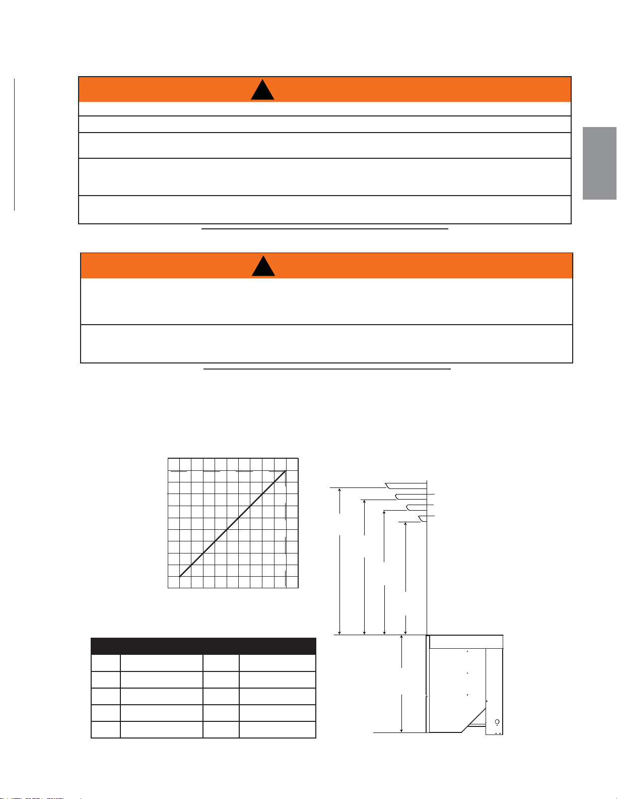
53
W415-1343 / A / 11.18.16
FR
4.0 FINITIONS
Le dégagement d'une tablette combustible à l'appareil peut varier selon la profondeur de la tablette. Utilisez
le graphique pour vous aider à déterminer le dégagement nécessaire. Les mêmes dégagements aux
matériaux combustibles s'appliquent pour toutes les surfaces en projection sur les côtés de l'appareil.
!
AVERTISSEMENT
RISQUE D’INCENDIE. CONSERVEZ TOUS LES DÉGAGEMENTS AUX MATÉRIAUX COMBUSTIBLES
SPÉCIFIÉS. NE PAS RESPECTER CES INSTRUCTIONS PEUT CAUSER UN INCENDIE OU UNE
SURCHAUFFE. ASSUREZ-VOUS QUE TOUS LES DÉGAGEMENTS (ARRIÈRE, CÔTÉS, DESSUS,
ÉVENTS, TABLETTE, FAÇADE, ETC.) SONT RESPECTÉS À LA LETTRE.
LORSQUE VOUS UTILISEZ DE LA PEINTURE OU DU VERNIS COMME FINITION POUR VOTRE
TABLETTE, ASSUREZ-VOUS QU’ILS SOIENT RÉSISTANTS À LA CHALEUR AFIN DE
PRÉVENIR LA DÉCOLORATION.
73.1
!
AVERTISSEMENT
RISQUE D’INCENDIE!
N’OBSTRUEZ JAMAIS L’OUVERTURE SUR LE DEVANT DE L’APPAREIL.
SI LA FINITION DE LA FAÇADE DE L’APPAREIL EST FAIT, ELLE DOIT ÊTRE FAITE DE MATÉRIAU
INCOMBUSTIBLE COMME DE LA BRIQUE, DU MARBRE, DU GRANITE, ETC.
NE FRAPPEZ PAS, NE CLAQUEZ PAS ET N’ÉGRATIGNEZ PAS LA PORTE VITRÉE. NE FAITES PAS
FONCTIONNER L’APPAREIL LORSQUE LA PORTE VITRÉE EST ENLEVÉE, FISSURÉE, BRISÉE OU
ÉGRATIGNÉE.
LES MATÉRIAUX DE FAÇADE OU DE FINITION NE DOIVENT JAMAIS EMPIÉTER SUR L’OUVERTURE
DE L’APPAREIL.
72.1B
4.1 DÉGAGEMENTS MINIMAUX DE LA TABLETTE
14”
(35,6cm)
17”
(43,2cm)
16”
(40,6cm)
15”
(38,1cm)
6”(152,4mm)
TABLETTE
5”(127mm)
3” (76,2mm)
4”(101,6mm)
20
1
/
2
”
(52,1cm)
3
14
5
4
0
6
15
16
17
7
$
%
/
(
7
7
(
+
$
8
7
(
8
5
'
(
/
$
PROJECTION DE
LA TABLETTE
DIMENSIONS DE TABLETTE
Ref Height Ref Depth
A
17" (43,2cm)
E
6" (152mm)
B
16" (40,6cm)
F
5" (127mm)
C
15" (38,1cm)
G
4" (102mm)
D
14” (35,6cm)
H
3" (76mm)
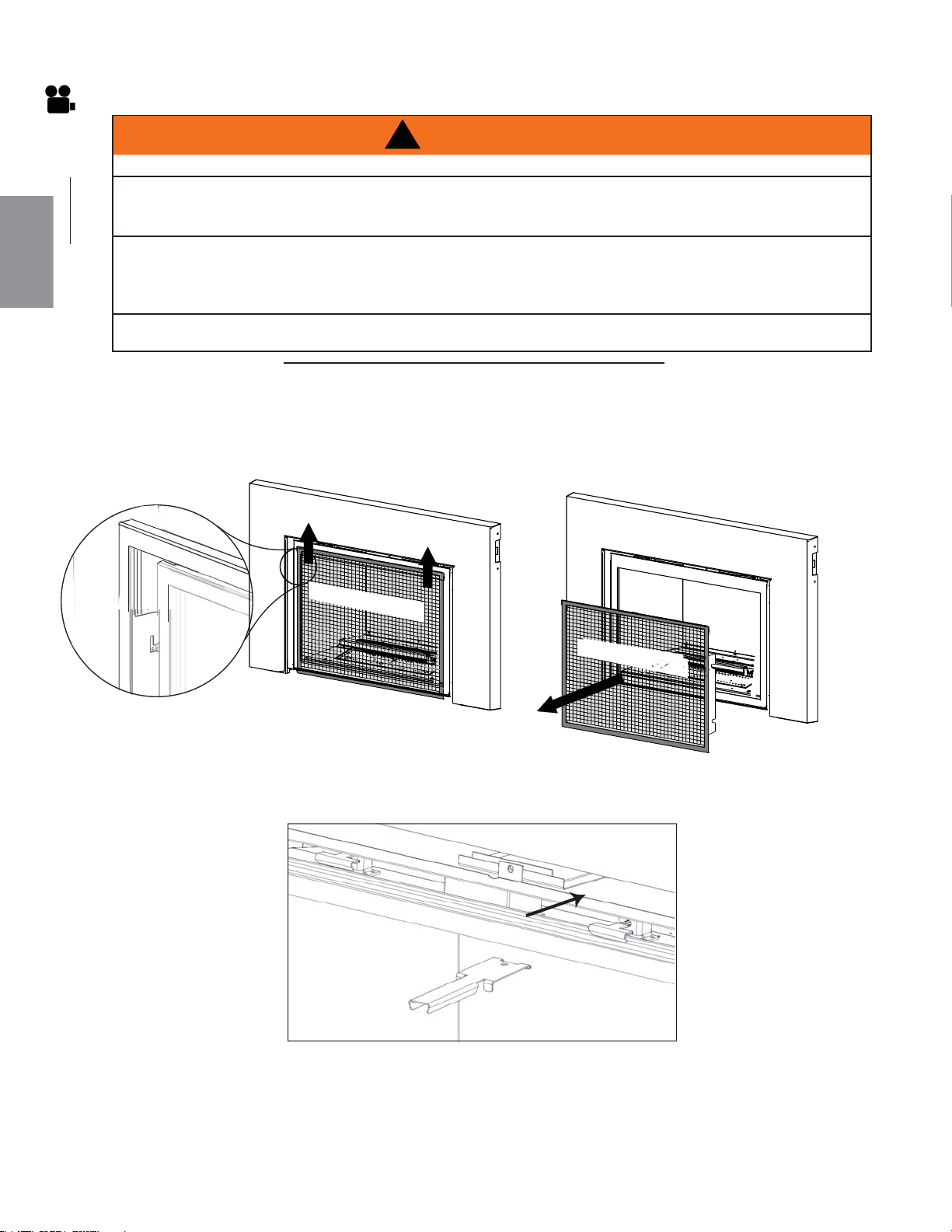
54
W415-1343 / A / 11.18.16
FR
4.2 ENLÈVEMENT ET INSTALLATION DE LA PORTE
!
AVERTISSEMENT
LA VITRE PEUT ÊTRE CHAUDE, NE TOUCHEZ PAS LA VITRE JUSQU’À CE QU’ELLE AIT REFROIDI.
SI ÉQUIPÉ AVEC LES LOQUETS DE PORTE QUI FONT PARTIE D'UN DISPOSITIF DE SÉCURITÉ ET DOIVENT
ÊTRE ADÉQUATEMENT VERROUILLÉS. NE FAITES PAS FONCTIONNER L’APPAREIL LORSQUE LES LOQUETS
SONT DÉVERROUILLÉS.
LES MATÉRIAUX DE FAÇADE ET DE FINITION NE DOIVENT PAS NUIRE À LA CIRCULATION DE L'AIR DANS LES
OUVERTURES D'AIR ET LES PERSIENNES, NI AU FONCTIONNEMENT DES PERSIENNES OU DES PORTES. ILS
NE DOIVENT PAS NON PLUS ENTRAVER L'ACCÈS POUR L'ENTRETIEN. RESPECTEZ TOUS LES DÉGAGEMENTS
AUX MATÉRIAUX COMBUSTIBLES.
AVANT D’ENLEVER LA PORTE, ÉTEIGNEZ L’APPAREIL ET ATTENDEZ QUE CE DERNIER SOIT FROID AU
TOUCHER. LES PORTES SONT LOURDES ET FRAGILES; MANIPULEZ AVEC SOIN.
75.1A
Une barrière conçu à réduire le risque de brûlures à partir de le chaude la vitre est à condition que
avec l’appareil et sera être installés.
Avant d’enlever la porte vitrée, l'écran de protection doit être enlever. Soulevez l’écran de protection hors
des 4 goupilles et enlever de l’appareil, puis inclinez la partie haut du porte vitrée puis enlever de l'appareil.
Avant de pouvoir ouvrir ou fermer la porte vitrée, la façade optionnelle doit être retirée. Déverrouillez les
loquets supérieurs gauche et droit situés dans le haut de la porte. Penchez légèrement vers l'avant puis
soulevez hors des fentes.
Inversez ces étapes pour réinstaller l'écran de protection et la porte. Assurez la l'écran de protection est
correctement installé.
SAFETY SCREEN
SAFETY SCREEN
SAFETY SCREEN
ÉCRAN DE
PROTE
CTION
ÉCRAN DE PROTECTION
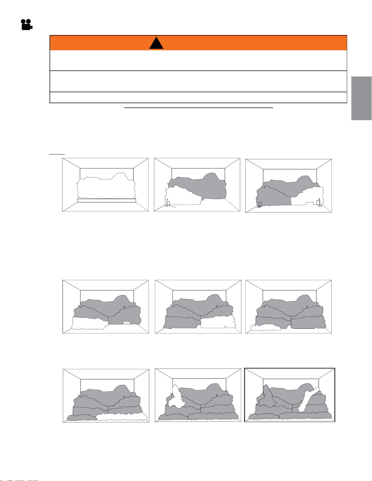
55
W415-1343 / A / 11.18.16
FR
4.3 DISPOSITION DES BÛCHES
!
AVERTISSEMENT
OMETTRE DE POSITIONNER LES BÛCHES CONFORMÉMENT AUX SCHÉMAS OU OMETTRE
D’UTILISER UNIQUEMENT DES BÛCHES SPÉCIFIQUEMENT APPROUVÉES POUR CET APPAREIL
PEUT CAUSER DES DOMMAGES MATÉRIELS OU DES BLESSURES CORPORELLES.
LES BÛCHES DOIVENT ÊTRE PLACÉES CORRECTEMENT À L’INTÉRIEUR DE L’APPAREIL. NE CHANGEZ PAS LA
POSITION DES BÛCHES CAR L’APPAREIL RISQUE DE NE PAS FONCTIONNER ADÉQUATEMENT ET UN RETARD
D’ALLUMAGE RISQUE DE SE PRODUIRE.
LES BÛCHES SONT FRAGILES ET DEVRAIENT ÊTRE MANIPULÉES AVEC SOIN.
76.1A
Les bûches PHAZER
MD
et les braises incandescentes, exclusives aux appareils Napoléon, créent un effet
incandescent réaliste et unique qui est différent dans chaque installation. Prenez le temps de bien installer les
braises incandescentes pour obtenir le meilleur effet possible. La couleur des bûches peut varier. Lors de la
première utilisation de l'appareil, les couleurs deviendront plus uniformes à mesure que leurs pigments seront
« absorbés » pendant le procédé de « cuisson ».
LOG SUPPORT
PIN
G. Placez la bande de charbon de
bois droite devant la bûche avant
droite, en alignant les deux trous
sous la bande avec les deux tiges
avant droites.
H. Insérez une tige dans le trou
du côté gauche de la bûche
centrale gauche, mettez la bûche
transversale gauche en place, en
alignant le trou supérieur avec la
tige.
C. Insérez l'extrémité de la bûche
centrale droite sur la tige de la
bûche centrale gauche. Placez
le support bûche droit (fourni)
devant le bûche au milieu à droite
et fixez avec la vis fourni. Ajustez
les supports à bûche de façon
serrée contre ces bûches afin de les
maintenir debout et assurez-vous
qu'elles soient serrées contre le
brûleur.
F. Placez la bande de charbon de
bois gauche devant la bûche avant
gauche, en alignant les deux trous
sous la bande avec les deux tiges
avant gauches.
A. Mettez la bûche arrière en place,
en alignant les trous sous la bûche
avec les tiges situées à l'arrière de la
chambre de combustion. Assurez-
vous qu'elle soit serrée contre le
brûleur.
B.
Insérez une goujon (fourni)
dans l'extrémité droite de la bûche
milieu gauche. Fixez le support de
bûche gauche (fourni) à l'avant de
la bûche centrale gauche et le fixer
avec la vis fourni.
E. Mettez la bûche avant droite
en place, en alignant les deux
trous sous la bûche avec les tiges
situées sur le côté droit du brûleur.
D. Mettez la bûche avant gauche
en place, en alignant les deux
trous sous la bûche avec les tiges
situées sur le côté gauche du
brûleur.
I. Insérez une tige dans le
trou du côté droit de la bûche
centrale droite, mettez la bûche
transversale droite en place, en
alignant le trou supérieur avec la
tige.
NOTE: Les supports de bûche sont fourni dans le sac manuel
SUPPORT
GOUJON
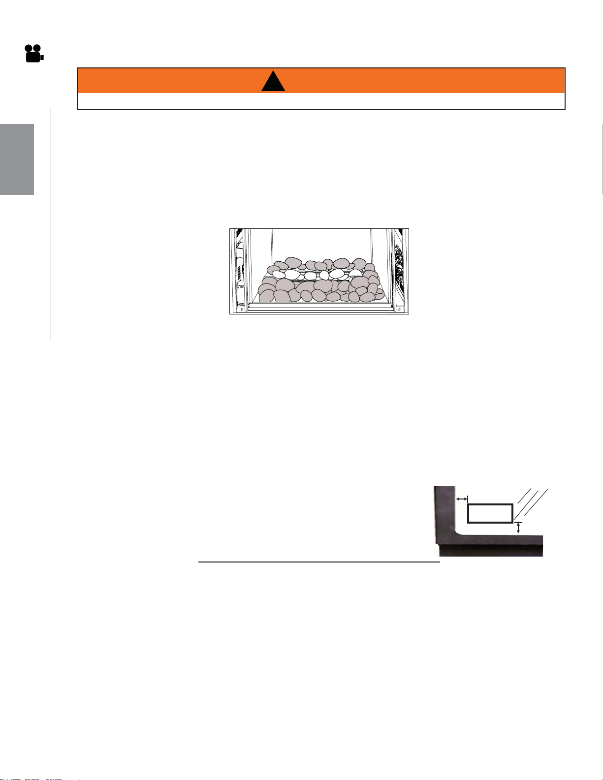
56
W415-1343 / A / 11.18.16
FR
Déchirez les braises incandescentes en morceaux et placez-les le long de la première rangée des orifices du
brûleur en couvrant toute la surface à l’avant des petites bûches. Les braises devraient être déchirées très
soigneusement en petits morceaux minces irréguliers, car seuls les côtés exposés des fibres deviendront
incandescents. Les braises seront incandescentes seulement lorsqu'elles sont exposées à une flamme
directe; cependant, prenez bien garde de ne pas boucher les orifices du brûleur.
Le blocage des orifices du brûleur peut créer une flamme irrégulière, des dépôts de carbone et un retard
d’allumage. Les bûches PHAZER
MD
rougeoient lorsqu’elles sont exposées à une flamme directe. N’utilisez
que des braises incandescentes et des bûches certifiées PHAZER
MD
, disponibles chez votre détaillant
autorisé.
97.1A
Retirez le papier dorsal du logo et placez-le sur la porte vitrée tel qu’indiqué.
LOGO
½"(12,7mm)
½"(12,7mm)
4.4 PLACEMENT DE LA ROCHES OPTIONNELLE
4.5 BRAISES INCANDESCENTES
4.6 MISE EN PLACE DU LOGO
Avant de commencer l'installation, retirez la porte, les bûches, les bandes de charbon de bois et les braises
incandescentes de l'appareil. Conservez les braises incandescentes.
A. Placez les roches au hasard sur le plateau, autour, mais pas sur les orifi ces du brûleur ou le pilote.
B. Les roches peut-être soigneusement empilées. Vous devez assurez que les roches ne tombera
pas sur les orifi ces du brûleur ou le pilote pendant le fonctionnement.
C. Branchez le gaz et l’alimentation électrique à l’appareil.
D. Réinstallez les braises incandescentes par-dessus le brûleur.
E. Réinstallez la porte.
!
AVERTISSEMENT
NE PAS UTILISER DE VRAIES ROCHES DANS CET APPAREIL. LA CHALEUR LES FERA EXPLOSER.
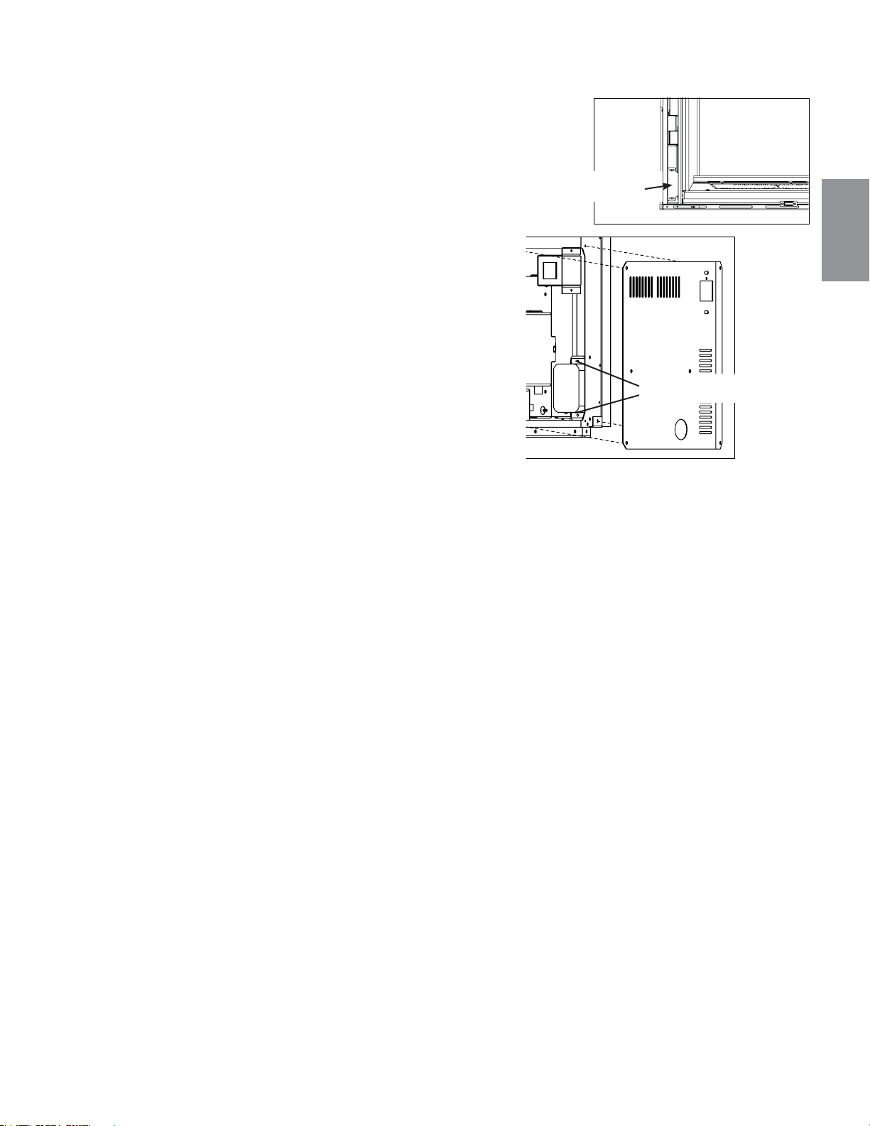
57
W415-1343 / A / 11.18.16
FR
4.7 INSTALLATION DES PILES
Pour que le XIR3 soit fonctionnel, vous devez installer 4 piles
« AA » dans le récepteur. Le récepteur est situé dans le coin
inférieur gauche de l'appareil.
Si vous devez enlever le récepteur, retirez le panneau d'accès
gauche du devant de l'appareil. Enlevez les deux vis servant à
fixer le récepteur. Tirez le récepteur à travers l'ouverture d'accès
puis remplacer.
RÉCEPTEUR
VIS DU RÉCEPTEUR
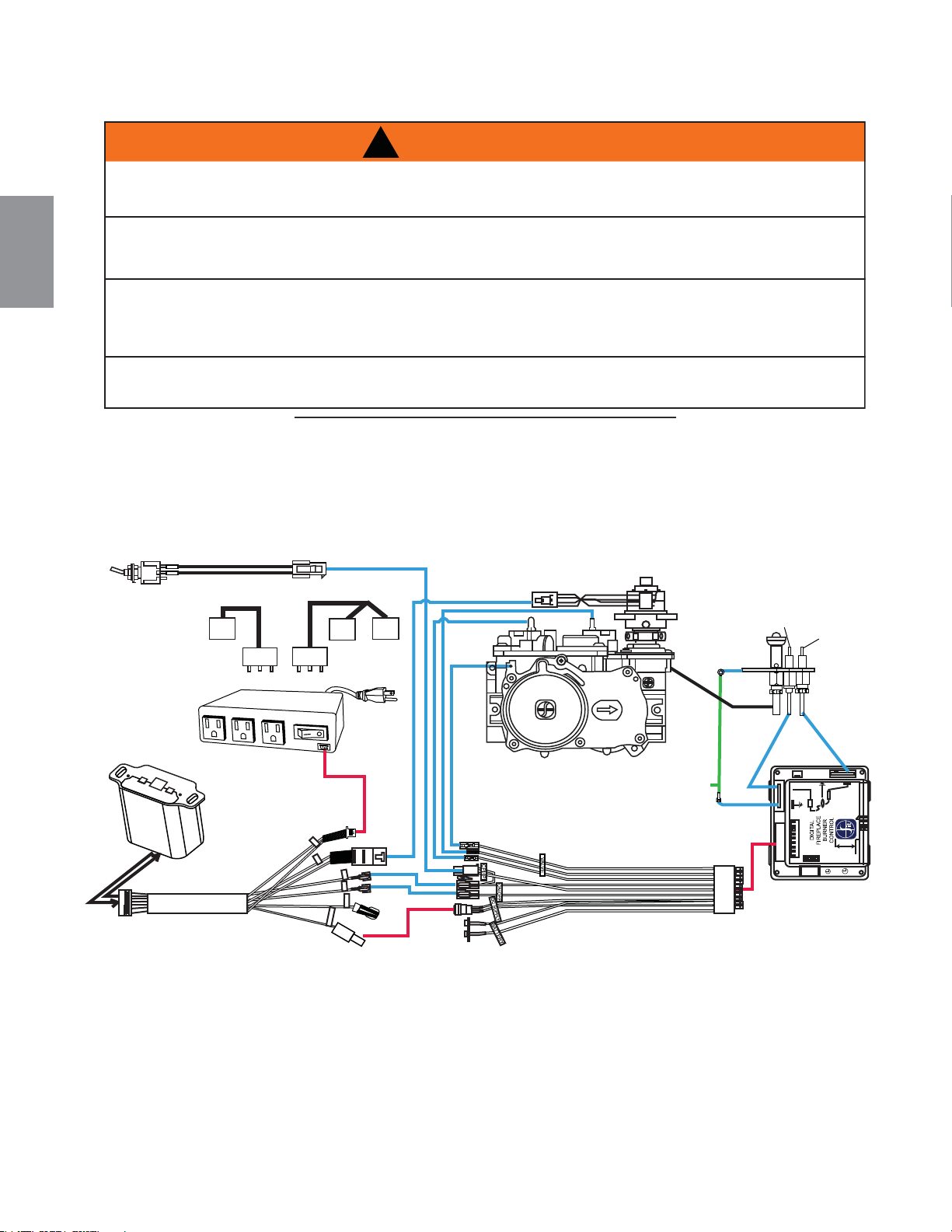
58
W415-1343 / A / 11.18.16
FR
5.0 INFORMATION ÉLECTRIQUE
!
AVERTISSEMENT
N’UTILISEZ PAS CE FOYER SI UNE PARTIE QUELCONQUE A ÉTÉ SUBMERGÉE. CONTACTEZ
IMMÉDIATEMENT UN TECHNICIEN DE SERVICE QUALIFIÉ POUR INSPECTER L’APPAREIL POUR
DES DOMMAGES AU CIRCUIT ÉLECTRIQUE.
RISQUE DE CHOCS ÉLECTRIQUES OU D’EXPLOSION. NE BRANCHEZ PAS LE 110 V À LA SOUPAPE
OU À L’INTERRUPTEUR MURAL DE L’APPAREIL. UN BRANCHEMENT ÉLECTRIQUE INCORRECT
ENDOMMAGERA LES CONTRÔLES.
CET APPAREIL DOIT ÊTRE RACCORDÉ ÉLECTRIQUEMENT PAR UN ÉLECTRICIEN QUALIFIÉ
CONFORMÉMENT AUX CODES LOCAUX. EN L’ABSENCE DE CODES LOCAUX, UTILISEZ LA
VERSION COURANTE DU CODE CANADIEN DE L'ÉLECTRICITÉ CSA C22.1 AU CANADA OU LE
NATIONAL ELECTRICAL CODE ANSI/NFPA 70 AUX ÉTATS-UNIS.
ALLUMEZ TOUJOURS LA VEILLEUSE, QUE CE SOIT POUR LA PREMIÈRE FOIS OU LORSQUE
L’APPROVISIONNEMENT EN GAZ EST ÉPUISÉ, AVEC LA PORTE VITRÉE OUVERTE OU RETIRÉE.
69.2
5.1 SCHÉMA DE CÂBLAGE
Assemblage du harnais de fils
Carte de circuits
imprimés IPI
Fil de terre
de la
veilleuse
Veilleuse
AE
Électrode d’allumage
Sonde de
flamme
Soupape à
modulation électronique
120V OUT
FAN
AUX OUT
COM
POWER
Interrupteur ACS/IPI
Récepteur
Harnais de fils
Module de contrôle
Lumières
de veille
Soufflerie
Prise du
harnais de
fils
Cet appareil est équipé d'un système de dépannage à piles. Si le système de dépannage à piles est utilisé,
installez quatre piles « AA » (non fournies) dans le récepteur.
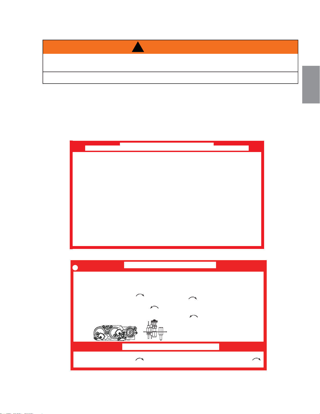
59
W415-1343 / A / 11.18.16
FR
6.0 FONCTIONNEMENT
Lorsqu’il est allumé pour la première fois, l'encastré dégagera une légère odeur pendant quelques heures.
Cela est une condition normale temporaire causée par l’évaporation des peintures et lubrifiants internes
utilisés dans le processus de fabrication; elle ne se reproduira plus. Après de longues périodes sans utiliser
l'appareil, comme à la suite de vacances ou à la fin de l’été, il se peut qu’une légère odeur se dégage pendant
quelques heures. Ceci est causé par des particules de poussière brûlant dans l’échangeur de chaleur. Dans
les deux cas, ouvrez une fenêtre pour aérer la pièce.
SI CES INSTRUCTIONS NE SONT PAS SUIVIES À LA LETTRE, UN INCENDIE OU UNE EXPLOSION
POURRAIENT S’ENSUIVRE, CAUSANT DES DOMMAGES MATÉRIELS,DES BLESSURES CORPORELLES OU
DES PERTES DE VIE.
ALLUMEZ TOUJOURS LA VEILLEUSE, QUE CE SOIT POUR LA PREMIÈRE FOIS OU LORSQUE
L’APPROVISIONNEMENT EN GAZ EST ÉPUISÉ, AVEC LA PORTE VITRÉE OUVERTE OU RETIRÉE.
!
AVERTISSEMENT
6.1 INSTRUCTIONS D'OPÉRATION ET D'ALLUMAGE
WARNING:
DO NOT TURN ON IF CHILDREN OR OTHER AT RISK
INDIVIDUALS ARE NEAR THE APPLIANCE. IF YOU DO NOT FOLLOW THESE
INSTRUCTIONS EXACTLY, A FIRE OR EXPLOSION MAY RESULT CAUSING
PROPERTY DAMAGE, PERSONAL INJURY OR LOSS OF LIFE.
INITIAL LIGHTING OF THE PILOT AND MAIN BURNERS MUST BE DONE
WITH THE GLASS DOOR OFF.
DO NOT CONNECT VALVE OR WALL SWITCH TO ELECTRICITY. SEE
INSTALLATION INSTRUCTIONS.
A. THIS APPLIANCE IS EQUIPPED WITH AN IGNITION DEVICE WHICH AUTOMATICALLY
LIGHTS THE PILOT. DO NOT TRY TO LIGHT BY HAND.
B. BEFORE OPERATING, SMELL ALL AROUND THE APPLIANCE AREA FOR GAS AND NEXT TO
THE FLOOR BECAUSE SOME GAS IS HEAVIER THAN AIR AND WILL SETTLE ON THE
FLOOR.
WHAT TO DO IF YOU SMELL GAS:
78512))$//*$6727+($33/,$1&(
23(1:,1'2:6
'212775<72/,*+7$1<$33/,$1&(
'2127728&+$1<(/(&75,&$/6:,7&+'212786($1<3+21(,1<285
BUILDING.
,00(',$7(/<&$//<285*$66833/,(5)520$1(,*+%285¶63+21()2//2:7+(
*$66833/,(5¶6,16758&7,216
,)<28&$11275($&+<285*$66833/,(5&$//7+(),5('(3$570(17
C. DO NOT TRY TO REPAIR ANY PART OF THIS ASSEMBLY. CALL A QUALIFIED SERVICE
TECHNICIAN. FORCE OR ATTEMPTED REPAIR MAY RESULT IN A FIRE OR EXPLOSION.
D. DO NOT USE THIS APPLIANCE IF ANY PART HAS BEEN UNDER WATER. IMMEDIATELY
CALL A QUALIFIED SERVICE TECHNICIAN TO INSPECT THE APPLIANCE AND REPLACE
ANY PART OF THE CONTROL SYSTEM AND ANY GAS CONTROL WHICH HAS BEEN UNDER
WATER.
ATTENTION:
1(3$6$//80(56,'(6(1)$17628'¶$875(6
INDIVIDUS À RISQUE SONT À PROXIMITÉ DU FOYER. QUICONQUE NE
RESPECTE PAS À LA LETTRE LES INSTRUCTIONS DANS LA PRÉSENTE
NOTICE, RISQUE DE DÉCLENCHER UN INCENDIE OU UN EXPLOSION
ENTRAÎNANT DES DOMMAGES, DES BLESSURES OU LA MORT.
/¶$//80$*(,1,7,$/'(/$9(,//(86((7'8%5Ó/(8535,1&,3$/
DOIT SE FAIRE AVEC LA PORTE VITRÉE ENLEVÉE.
1(5$&&25'(=3$6/$6283$3(28/¶,17(55837(85085$/¬
/¶e/(&75,&,7e&2168/7(=/(6,16758&7,216'¶,167$//$7,21
$&(7$33$5(,/(67081,'¶81',6326,7,)'¶$//80$*(48,$//80(
$8720$7,48(0(17/$9(,//(86(1(7(17(=3$6'¶$//80(5/$9(,//(86(
MANUELLEMENT.
%$9$17'()$,5()21&7,211(55(1,)/(=7287$87285'(/¶$33$5(,/3285
DÉCELER UN ODEUR DE GAZ. RENIFLEZ PRÈS DU PLANCHER, CAR CERTAINS GAZ
62173/86/285'648(/¶$,5(73(89(176¶$&&808/(5$81,9($8'862/
QUE FAIRE SI VOUS DÉTECTEZ UNE ODEUR DE GAZ:
&283(=/¶$/,0(17$7,21'(*$=35,1&,3$/(
2895(=/(6)(1Ç75(6
1(3$67(17(5'¶$//80(5'¶$33$5(,/
1(728&+(=¬$8&81,17(55837(851(3$692866(59,5'(67e/e3+21(66(
TROUVANT DANS LE BÂTIMENT.
$33(/(=,00e',$7(0(179275()2851,66(85'(*$='(38,68192,6,1
SUIVEZ LES INSTRUCTIONS DU FOURNISSEUR.
6,92861(3289(=5(-2,1'5(/()2851,66(85$33(/(=/(6(59,&('(6
INCENDIES.
&1¶(66$<(=3$6'(5e3$5(5$8&81(3,Ê&('(&(7$66(0%/$*($33(/(=81
7(&+1,&,(148$/,),e)25&(5287(17(5'(5e3$5(5/¶$66(0%/$*(32855$,7
CAUSER UN FEU OU UNE EXPLOSION.
'1¶87,/,6(=3$6&(7$33$5(,/6¶,/$e7e3/21*e'$16/¶($80Ç0(
3$57,(//(0(17)$,7(6,163(&7(5/¶$33$5(,/3$5817(&+1,&,(148$/,),e(7
REMPLACEZ TOUTE PARTIE DU SYSTÈME DE CONTRÔLE ET TOUTE COMMANDE QUI
217e7e3/21*e6'$16/¶($8
OPERATING INSTRUCTIONS / INSTRUCTIONS D’OPÉRATION
FOR YOUR SAFETY READ BEFORE OPERATING / POUR VOTRE SÉCURITÉ LIRE AVANT DE FAIRE FONCTIONNER
W385-0460 / E
W385-0460 / E
LIGHTING INSTRUCTIONS / INSTRUCTIONS D’ALLUMAGE
1. STOP! READ ALL INFORMATION OF OPERATING AND LIGHTING
INSTRUCTIONS BEFORE PROCEEDING.
2. TURN OFF ELECTRICAL POWER TO THE APPLIANCE.
3. THIS APPLIANCE IS EQUIPPED WITH AN IGNITION DEVICE WHICH
AUTOMATICALLY LIGHTS THE PILOT. DO NOT TRY TO LIGHT THE PILOT
BY HAND.
4. OPEN THE GLASS DOOR.
5. TURN MANUAL SHUTOFF VALVE CLOCKWISE TO OFF.
6. WAIT FIVE (5) MINUTES TO CLEAR OUT ANY GAS. IF YOU SMELL GAS,
INCLUDING NEAR THE FLOOR, STOP! FOLLOW “B” OF THE OPERATING
INSTRUCTIONS. IF YOU DON’T SMELL GAS, GO TO THE NEXT STEP.
7. TURN MANUAL SHUTOFF VALVE COUNTER-CLOCKWISE TO ON.
8. CLOSE THE GLASS DOOR.
9. TURN ON ALL ELECTRICAL POWER TO THE APPLIANCE.
10. TURN ON MAIN BURNER.
1. ARRÊTEZ! LISEZ TOUTES LES INSTRUCTIONS DE
FONCTIONNEMENT ET D’ALLUMAGE AVANT DE CONTINUER.
2. COUPEZ L’ALIMENTATION ÉLECTRIQUE À L’APPAREIL.
3. CET APPAREIL EST MUNI D’UN DISPOSITIF D’ALLUMAGE QUI
ALLUME LA VEILLEUSE AUTOMATIQUEMENT, N’ESSAYEZ PAS
D’ALLUMER LA VEILLEUSE MANUELLEMENT.
4. OUVREZ LA PORTE VITRÉE.
5. TOURNEZ LA SOUPAPE DE SECTIONNEMENT MANUELLE VERS LA
DROITE À « OFF ».
6. ATTENDEZ CINQ (5) MINUTES POUR QUE LE GAZ PUISSE
S’ÉCHAPPER. SI VOUS DÉTECTEZ UNE ODEUR DE GAZ, ARRÊTEZ!
SUIVEZ « B » DANS LES INSTRUCTIONS DE FONCTIONNEMENT.
S’IL N’Y A PAS D’ODEUR DE GAZ, PASSEZ À L’ÉTAPE SUIVANTE.
7. TOURNEZ LA SOUPAPE DE SECTIONNEMENT MANUELLE VERS LA
GAUCHE À « ON ».
8. FERMEZ LA PORTE VITRÉE.
9. RÉTABLISSEZ L’ALIMENTATION ÉLECTRIQUE AU FOYER.
10. ALLUMEZ LE BRÛLEUR PRINCIPAL.
1. TURN OFF ALL ELECTRICAL POWER TO THE APPLIANCE IF SERVICE IS
TO BE PERFORMED.
2. TURN MANUAL SHUTOFF VALVE CLOCKWISE TO OFF. DO NOT
FORCE.
1. COUPEZ L’ALIMENTATION ÉLECTRIQUE AU FOYER SI UN TRAVAIL
D’ENTRETIEN DOIT SE FAIRE.
2. TOURNEZ LA SOUPAPE D’ARRÉT MANUELLE VERS LA DROITE
À « OFF ». NE FORCEZ PAS.
TO TURN OFF GAS / INSTRUCTIONS POUR COUPER LE GAZ
ATERIAL
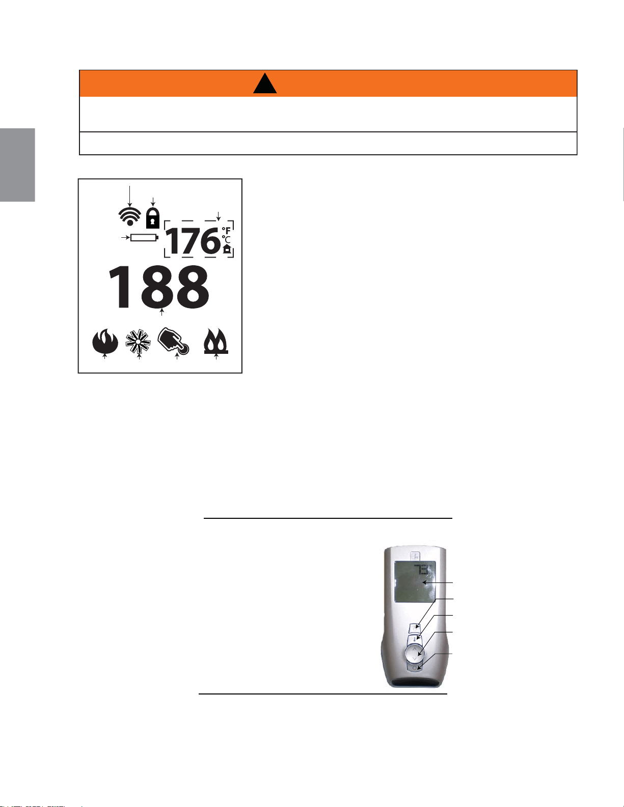
60
W415-1343 / A / 11.18.16
FR
6.2 XIR3 FONCTIONNEMENT
SI CES INSTRUCTIONS NE SONT PAS SUIVIES À LA LETTRE, UN INCENDIE OU UNE EXPLOSION
POURRAIENT S’ENSUIVRE, CAUSANT DES DOMMAGES MATÉRIELS,DES BLESSURES CORPORELLES OU
DES PERTES DE VIE.
ALLUMEZ TOUJOURS LA VEILLEUSE, QUE CE SOIT POUR LA PREMIÈRE FOIS OU LORSQUE
L’APPROVISIONNEMENT EN GAZ EST ÉPUISÉ, AVEC LA PORTE VITRÉE OUVERTE OU RETIRÉE.
!
AVERTISSEMENT
6.2.1 DESSIN GÉNÉRAL DE LA TÉLÉCOMMANDE
6.2.2 FONCTIONNEMENT DE L’APPAREIL
A. Installez 4 piles AA dans le compartiment à piles du récepteur, tel qu’indiqué sur le couvercle
(+/-). (Requis uniquement en tant qu’élément de secours en cas de panne de courant.)
B. Réglez l’interrupteur à glissière à « REMOTE ».
C. Insérez le bout d’un trombone, ou d’un objet similaire, dans le trou « PRG » situé sur le couvercle
avant du récepteur. Le récepteur émettra trois (3) bips pour indiquer qu’il est prêt à être synchronisé
avec la télécommande.
D. Installez les 3 piles AAA dans le compartiment à piles de la télécommande qui se trouve sur la base
de la télécommande. Appuyez ensuite sur la touche « ON ». Le récepteur émettra quatre (4) bips pour
indiquer que la commande de la télécommande est acceptée et réglée au code spécifi que de cette
télécommande. Le système est maintenant initialisé.
35.2A
6.2.3 FONCTIONEMENT DE LA TÉLÉCOMMANDE
A
. Appuyez sur la touche « ON/OFF » de la télécommande.
L’affi cheur de la télécommande affi chera toutes les icônes
actives à l’écran. Un bip unique du récepteur confi rmera la
réception de la commande.
35.4
AFFICHEUR ACL BLEU
TOUCHE ON/OFF
TOUCHE TEMPÉRATURE
TOUCHE HAUT/BAS
TOUCHE MODE
TEMPÉRATURE
RÉELLE
ALARME DE
PILE FAIBLE
VERROU DE SÉCURITÉ
POUR ENFANT
TRANSMISSION
FONCTION
AUXILIAIRE
SOUFFLERIEFLAMME
TEMPÉRATURE RÉGLÉE
BRÛLEUR
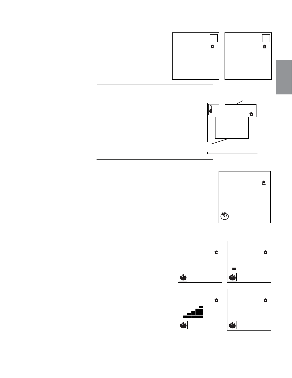
61
W415-1343 / A / 11.18.16
FR
La télécommande peut fonctionner comme un thermostat de pièce. Le
thermostat peut être réglé à une température désirée pour contrôler le
niveau de confort dans la pièce.
A. Appuyez sur la touche « THERMOSTAT ». L’affi cheur ACL
de la télécommande indiquera que la pièce est « ON » et la
température réglée est maintenant affi chée.
B. Pour ajuster la température réglée, appuyez sur la touche haut/
bas jusqu’à ce que la température désirée s’affi che sur l’écran
ACL de la télécommande.
35.6
76
°F
ON
68
TEMPÉRATURE RÉELLE
TEMPÉRATURE RÉGLÉE
6.2.4 AFFICHEUR DE TEMPÉRATURE
6.2.5 THERMOSTAT DE PIÈCE
A. Avec le système en position «OFF», appuyez
simultanément sur les touches «TEMPÉRATURE»
et « MODE » pour passer de l’affi chage de la
température en Fahrenheit à Celsius.
B. Vérifi ez l’affi cheur ACL de la télécommande pour
vous assurer que le C ou le F est visible à la droite
de l’affi chage de la température de la pièce.
35.5A
73
°F
23
°C
La
f
onction «
S
mart Thermostat »
(
thermostat intelligent
)
ajuste la hauteur de la
fl amme selon la différence entre la température réglée et la température réelle de la
pièce. Alors que la température de la pièce s’approche à celle du point de réglage, la
fonction Smart ajustera automatiquement la hauteur de la fl amme.
A. Appuyez sur la touche « THERMOSTAT » jusqu’à ce que le mot « SMART »
apparaisse à la droite de l’icône de thermomètre
B. Pour ajuster la température réglée, appuyez sur la touche haut/bas jusqu’à
ce que la température désirée s’affi che sur l’écran ACL de la télécommande.
35.7
76
°F
68
MAX
6.2.6 THERMOSTAT SMART
La télécommande comporte six (6) niveaux de fl ammes.
Avec le système en marche et le niveau de la fl amme
au maximum, appuyez une fois sur la touche bas
et cela réduira la hauteur de la fl amme d’un niveau
jusqu’à ce que la fl amme soit éteinte. La touche haut
augmentera la hauteur de la fl amme chaque fois qu’elle
est enfoncée. Si la touche haut est enfoncée lorsque le
système est en marche, mais que la fl amme est éteinte,
la fl amme s’allumera en position élevée. Un seul bip
confi rmera la réception de la commande.
35.8
76
°F
OFF
76
°F
76
°F
76
°F
Hi
FLAMME ÉTEINTE
FLAMME AU NIVEAU 1
FLAMME AU NIVEAU 5
FLAMME AU NIVEAU 6
«HAUT»
6.2.7 HAUTEUR DE LA FLAMME
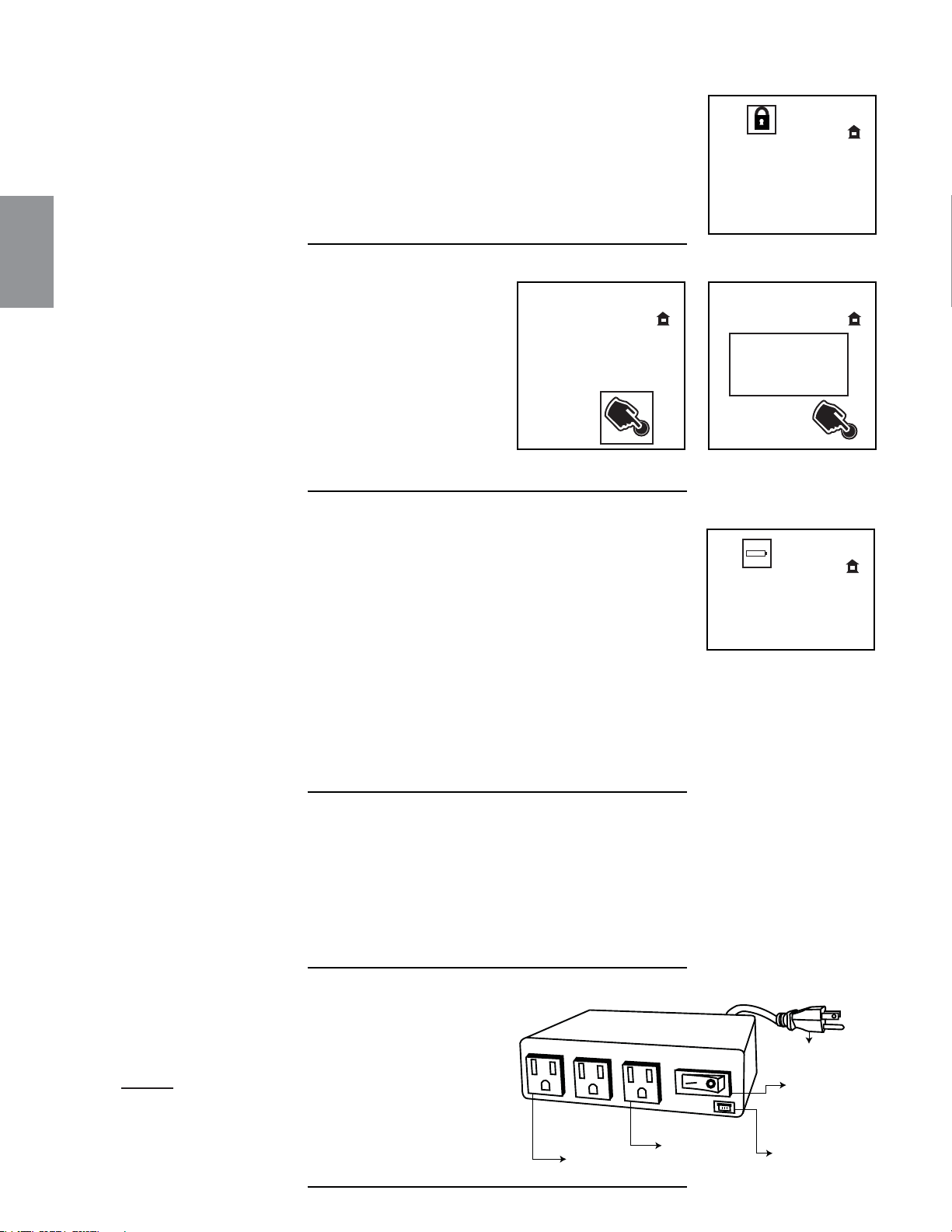
62
W415-1343 / A / 11.18.16
FR
Cette fonction verrouillera les touches pour empêcher une utilisation non supervisée.
A. Appuyez simultanément sur les touches « MODE » et haut.
B. Pour désactiver cette fonction, appuyez simultanément sur les touches
«MODE» et haut.
35.10A
76
°F
6.2.8 FONCTION DE SÉCURITÉ POUR ENFANTS
La fonction auxiliaire règle la prise d’alimentation aux-
iliaire du Module de contrôle qui, à son tour, ajuste la
lumière de veille.
A. Utilisez la touche « MODE » pour vous guider
vers l’icône « AUX ».
B. Appuyez sur la touche fl échée haut pour activer
la lumière de veille.
C. Appuyez sur la touche fl échée bas pour éteindre
la lumière de veille. Un bip unique confi rmera la réception de la commande.
35.12
76
°F
OFF
76
°F
ON
6.2.9 LUMIÈRE DE VEILLE
Le module de contrôle offre une prise 120 V AUX
télécommandée pour la lumière de veille et une prise
120 V à alimentation constante.
NOTE : L’interrupteur « ON/OFF » du module de contrôle
devrait toujours être à la position « ON ». Si pour une
raison quelconque le module est éteint, les composants
branchés au module n’auront aucune alimentation
électrique.
35.16
PRISE RÉSEAU
PRISE
AUXILIAIRE 120 V
FICHE
D’ALIMENTATION AU
RÉSEAU
INTERRUPTEUR
DU MODULE DE
CONTRÔLE
(ILLUSTRÉ EN
POSITION EN
MARCHE)
BUS DE
COMMUNICATION
(3 BROCHES)
6.2.10 PILES FAIBLES / DÉRIVATION MANUELLE
6.2.11 EN CAS DE PANNE DE COURANT
6.2.12 MODULE DE CONTRÔLE
Si le récepteur est muni de piles, celles-ci permettront au contrôle de la hauteur de la fl amme, au bouton
«ON/OFF» ou au thermostat de contrôler le foyer, lorsque survient une panne électrique. Reportez-vous
à la section « FONCTIONNEMENT DE L’APPAREIL » lorsque les communications entre le récepteur et la
télécommande sont rompues. Le récepteur émettra un bip pour confi rmer la réussite de la programmation une
fois que le courant est rétabli. Si le foyer était en marche au moment de la panne de courant, la hauteur de la
fl amme conservera son réglage. Si le foyer était éteint au moment de la panne, mais qu’il est allumé par la suite,
la hauteur de la fl amme sera à «HI». La hauteur de la fl amme peut alors être ajustée par la télécommande.
35.14A
La durée de vie des piles de la télécommande dépend de plusieurs facteurs : la
qualité des piles, le nombre d’allumage de l’appareil, le nombre de changements du
point de réglage du thermostat, etc.
Dès que les piles de la télécommande sont faibles, l’écran ACL affi che une icône de
pile. Celle-ci disparaît lorsque vous remplacez les piles.
Ne s’applique pas lorsque branché à l’alimentation 110 V.
Le récepteur vous avisera que ses piles sont faibles en n’émettant aucun bip
lorsqu’il reçoit une commande « ON/OFF ». Dès que les piles seront remplacées, le
récepteur émettra à nouveau un bip lorsque la touche « ON/OFF » sera enfoncée.
Si les piles du récepteur ou de la télécommande sont faibles, l’appareil peut être mis en marche manuellement
en glissant l’interrupteur à glissière du récepteur à la position «ON». Cela contournera les fonctions de la
télécommande et le brûleur principal de l’appareil se mettra en marche si la soupape de gaz est à la position «ON».
35.13A
76
°F
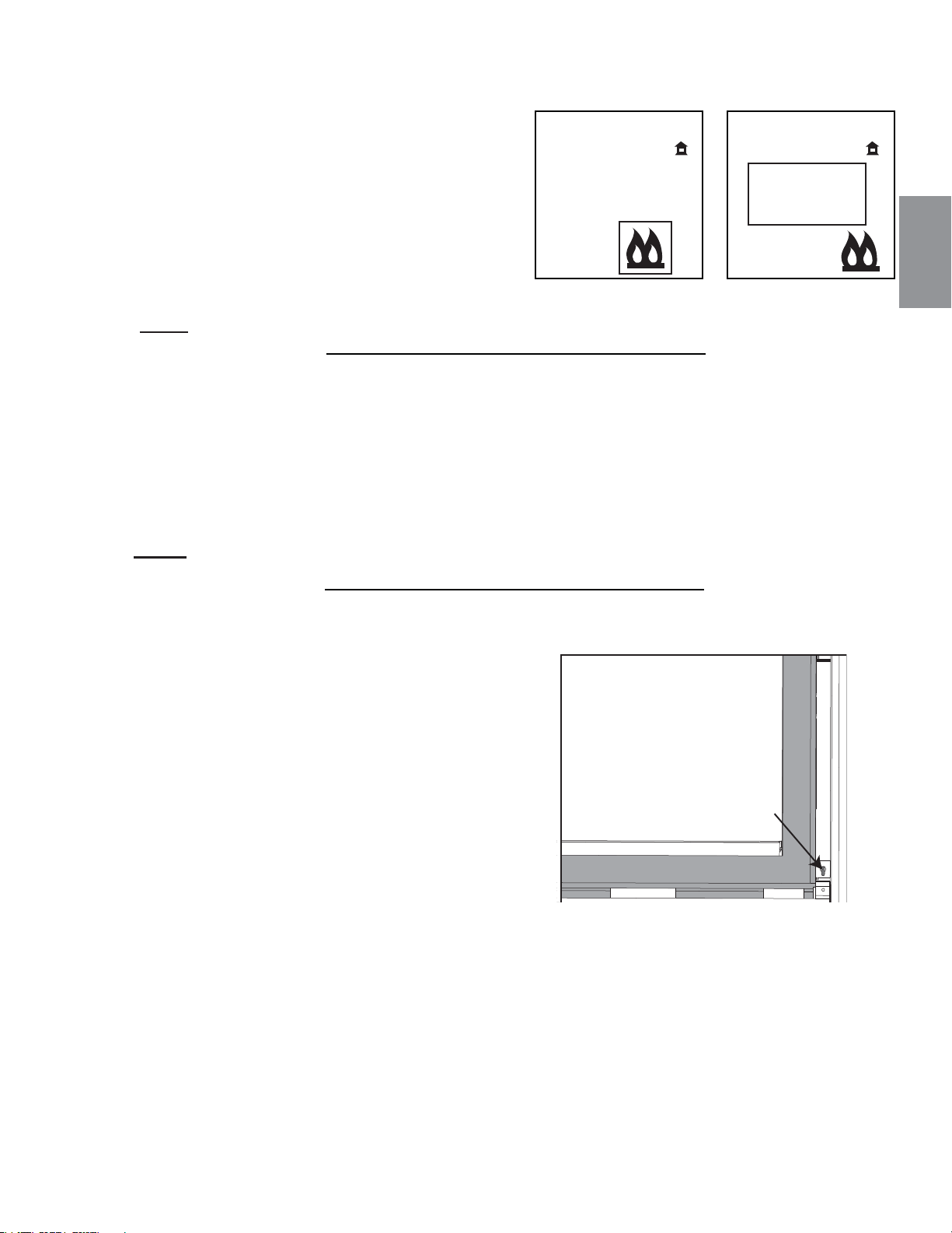
63
W415-1343 / A / 11.18.16
FR
La fonction brûleur contrôle la mise en marche et
l’arrêt du deuxième brûleur.
A. Utilisez la touche « MODE » pour vous guider
vers la fonction brûleur.
B. Appuyez sur la touche haut pour activer le
deuxième brûleur.
C. Appuyez sur la touche bas pour éteindre le
deuxième brûleur. Un seul bip confi rmera la
réception de la commande.
NOTE: Il n’est pas possible de contrôler la hauteur des fl ammes séparément.
35.17
76
°F
OFF
76
°F
ON
Votre télécommande est munie d’une minuterie intégrée (en mode thermostat) qui permet d’allumer et
d’éteindre la souffl erie automatiquement (si équipé) lorsque le brûleur s’allume et s’éteint. La vitesse de la
souffl erie étant déjà réglée sur la télécommande à la vitesse désirée, la souffl erie se mettra en marche environ
5 minutes après l’allumage du brûleur et s’arrêtera environ 12 minutes après la fermeture du brûleur.
Ce délai d’attente est conçu pour maximiser la distribution d’air chaud par la souffl erie.
Si à un moment ou l’autre le brûleur est réallumé avant que les douze minutes ne soient écoulées, la souffl erie
continuera de fonctionner.
NOTE : Lors de la séquence d’opération, la souffl erie (si équipé) peut être manuellement allumée/
fermée avec la télécommande à tout moment.
35.19B
CÔTÉ DROIT DU CADRE
DE PORTE (CÔTÉ
FONCTIONNEMENT)
INTERRUPTEUR
ANTICONDENSATION
Cet appareil a la possibilité de passer d’un mode de veilleuse électronique à allumage intermittent à un mode
de veilleuse permanente pour les climats froids.
6.2.13 SOUPAPE À DÉBIT DIVISÉ
6.2.14 MINUTERIE DE SOUFFLERIE
6.3 L'INTERRUPTEUR ANTICONDENSATION
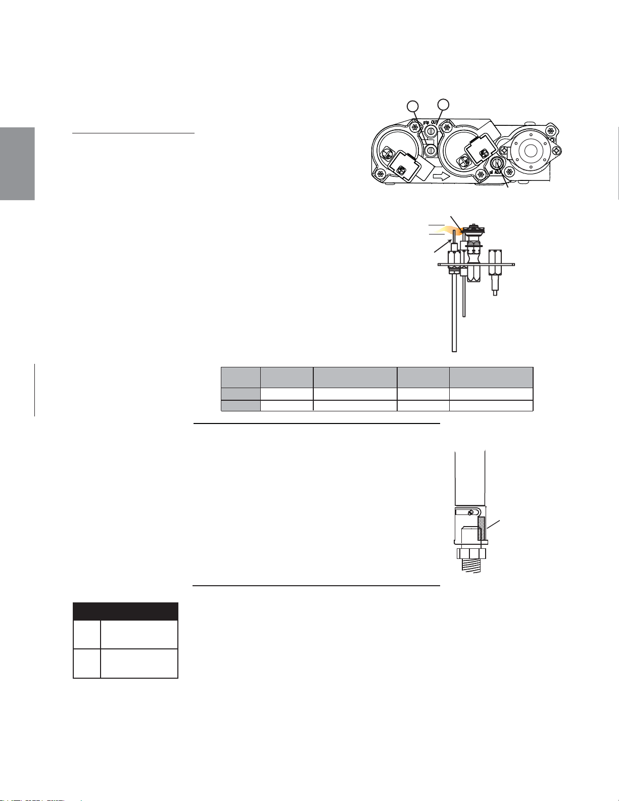
64
W415-1343 / A / 11.18.16
FR
7.0 RÉGLAGES
7.1 RÉGLAGE DE LA VEILLEUSE
7.2 RÉGLAGE DU VENTURI
Ajustez la vis de la veilleuse pour obtenir une fl amme de taille
normale. Tournez vers la droite pour réduire l’apport de gaz.
VÉRIFIER LA PRESSION :
Pour vérifi er la pression d’arrivée, tournez la vis (A) vers la
gauche deux à trois tours, puis emboîtez le tube du manomètre
sur la pointe d’essai. Le manomètre doit indiquer la pression
comme décrit sur le diagramme ci-dessous. Vérifi er la pression
avec brûleur principal sur « HI ».
La vérifi cation de la pression de sortie s’effectue comme ci-
dessus en utilisant la vis (B). Le manomètre doit indiquer la
pression comme décrit sur le diagramme ci-dessous. Vérifi er
la pression avec brûleur principal sur « HI ».
APRÈS AVOIR PRIS LA LECTURE DES PRESSIONS,
ASSUREZ-VOUS DE TOURNER FERMEMENT LES VIS
VERS LA DROITE POUR SCELLER. NE SEREZ PAS TROP FORT.
Vérifi ez pour des fuites en apliquant une solution d’eau savonneuse.
Avant d’effectuer le réglage de la veilleuse, assurez-vous que l’assemblage de la
veilleuse n’a pas été peint. S’il y a des traces de peinture ou de surpulvérisation,
enlevez-les de l’assemblage de la veilleuse ou remplacez-le. Une toile d’émeri
ou un tampon récurage (comme Scrotch-Brite™) peut être utilisé pour enlever la
peinture sur la hotte de la veilleuse, sur l’électrode et sur le capteur de fl amme.
39.1D
A
B
VIS DE LA VEILLEUSE
Pression
Gaz Naturel
(pouces)
Gaz Naturel
(millibars)
Propane
(pouces)
Propane
(millibars)
Arrivée *7” (min.4,5”) 17,4 mb (min.11,2mb) 13” (min.11”) 32,4 mb (min.27,4mb)
Sortie 3,5” 8,7 mb 10” 24,9 mb
3/8” - 1/2”
(9,5mm - 12,7mm)
LA FLAMME DOIT
ENVELOPPER LA PARTIE
SUPÉRIEURE DE LA SONDE
DE FLAMME DE 3/8” (9,5mm)
À 1/2” (12,7mm)
ÉLECTRODE
LA SONDE
DE FLAMME
VEILLEUSE
* Pression d’alimentation
maximale ne devait ne
pas dépasser 13”
L’ouverture du volet d’air a été préréglée en usine selon le tableau
ci-dessous :
Indépendamment de l’orientation du venturi, plus le volet est fermé,
plus la flamme est jaune et aura tendance à causer des dépôts de
carbone. Plus le volet est ouvert, plus la flamme est bleue et plus elle a
tendance à se détacher des orifices du brûleur. La flamme peut ne pas
être jaune immédiatement; allouez de 15 à 30 minutes pour que la
couleur finale de la flamme se stabilise.
LE RÉGLAGE DU VOLET D’AIR DOIT ÊTRE EXÉCUTÉ PAR UN
TECHNICIEN OU INSTALLATEUR QUALIFIÉ!
VENTURI
INJECTEUR
49.1
OUVERTURE
DU VOLET
D’AIR
XIR3
GN F 1/8"(3,2mm)
R 5/16"(8mm)
P F 1/2"(12,7mm)
R 3/8"(9,5mm)
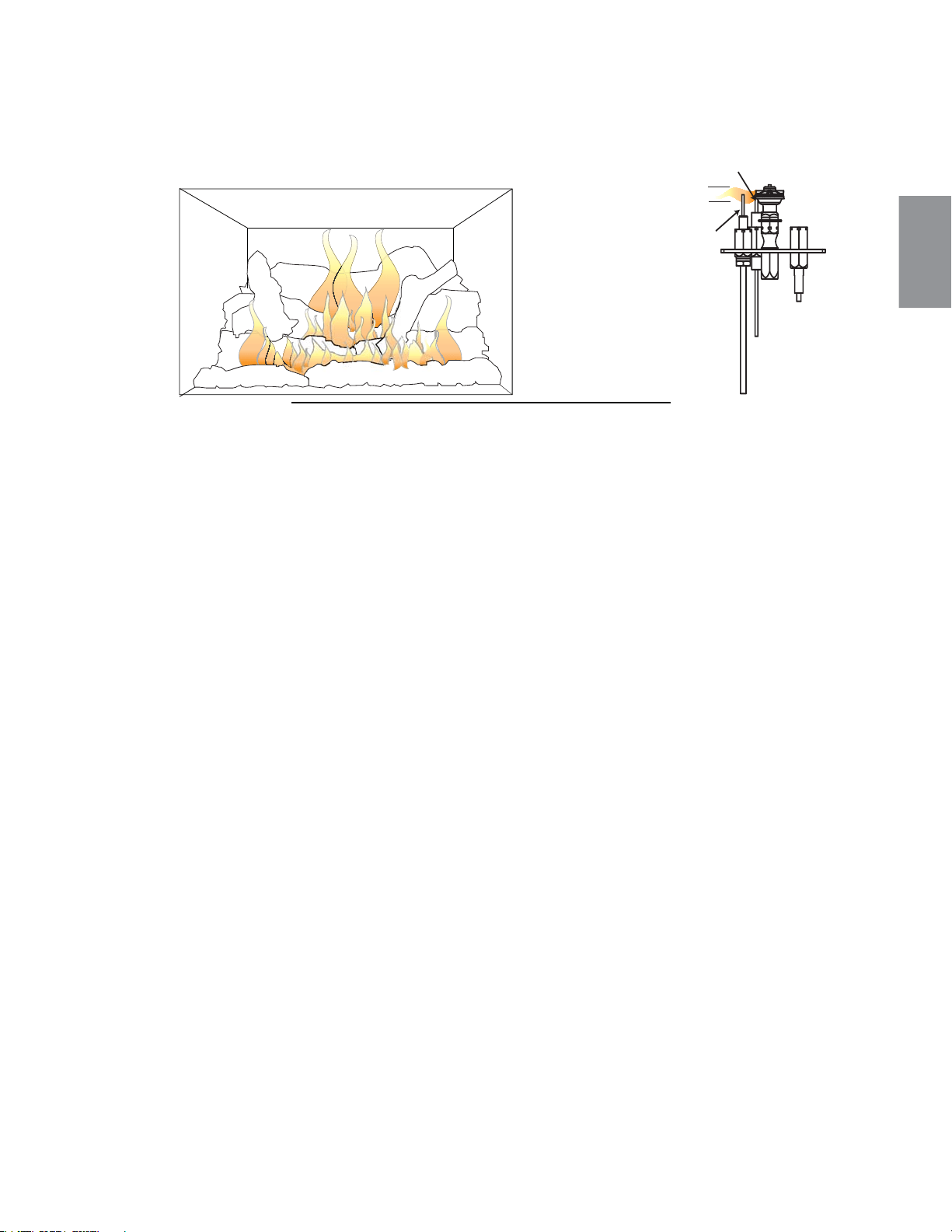
65
W415-1343 / A / 11.18.16
FR
7.3 CARACTÉRISTIQUES DE LA FLAMME
3/8” - 1/2”
(9,5mm - 12,7mm)
LA FLAMME DOIT
ENVELOPPER LA PARTIE
SUPÉRIEURE DE LA SONDE
DE FLAMME DE 3/8” (9,5mm)
À 1/2”
(
12,7mm
)
ÉLECTRODE
LA SONDE
DE FLAMME
VEILLEUSE
54.1B
Il est important d’effectuer périodiquement une inspection visuelle de la fl amme de la veilleuse et du brûleur.
Comparez-les à ces illustrations. Si des fl ammes paraissent anormales,
contactez un technicien de service.

66
W415-1343 / A / 11.18.16
FR
8.0 ENTRETIEN
Assurez-vous que l’appareil fonctionne adéquatement une fois l’entretien terminé. Cet appareil et son système
d’évacuation devraient être inspectés avant la première utilisation et au moins une fois l’an par un technicien
de service qualifi é. Les vérifi cations suggérées doivent être effectuées par un technicien qualifi é. L’espace
entourant l’appareil doit être gardé propre et libre de matériaux combustibles, d’essence ou autres liquides et
vapeurs infl ammables. Les apports d’air comburant et d’air de convection ne doivent pas être obstrués.
ATTENTION: Lors de l’entretien des contrôles, assurez-vous d’identifi er chacun des fi ls avant de les
débrancher. Une réinstallation incorrecte des fi ls peut occasionner un mauvais fonctionnement et être
dangereuse.
A. Pour nettoyer le brûleur principal et la veilleuse adéquatement, il faut retirer les bûches, les roches ou
la vitre afi n de dégager les deux ensembles.
B. Gardez le compartiment des contrôles, les composants décoratifs, le brûleur, le volet d’air et l’espace
entourant les bûches propres en brossant ou en passant l’aspirateur au moins une fois l’an.
C. Assurez-vous que tous les orifi ces des brûleurs produisent des fl ammes. Nettoyez tous les orifi ces
qui n’ont pas de fl amme ou dont la fl amme ne brûle pas adéquatement.
D. Assurez-vous que la fl amme de la veilleuse est assez puissante pour envelopper la sonde de fl amme
et/ou le thermocouple/thermopile et qu’elle atteigne le brûleur.
E. Remettez en place les bûches, les roches ou la vitre nettoyées, si équipé. Omettre de positionner les
composants décoratifs adéquatement peut causer des dépots de carbone qui peuvent se déposer à
l’intérieure de la chambre de combustion et sur les surfaces extérieures entourant d’évent.
F. Vérifi ez si le brûleur principal allume sur tous les orifi ces lorsque le bouton de contrôle du gaz est à
«ON». Un temps d’allumage total de 5 à 10 secondes est satisfaisant. Service selon les besoins.
G. Vérifi ez si les joints d’étanchéité sur les côtés, le haut et le bas de la porte ne sont pas brisés ou
manquants. Remplacez si nécessaire.
H. Si pour une raison quelconque le système d’évents de prise d’air est démonté, réinstallez et
rescellez-le selon les instructions fournies dans l’installation initiale.
I. Il est possible que l’écran de protection (pare-étincelles) nécessite un nettoyage occasionnel en
raison des peluches/poussières provenant des tapis, des animaux, etc. il suffi t de passer l’aspirateur
à l’aide de l’embout avec une brosse.
J. Vérifi ez si le système de décharge effectue effi cacement. Vérifi ez si les joints d’étanchéité ne sont pas
brisés ou manquants. Remplacez si nécessaire.
40.1E
!
AVERTISSEMENT
COUPEZ L’ALIMENTATION EN GAZ ET L’ALIMENTATION ÉLECTRIQUE AVANT DE PROCÉDER À
L’ENTRETIEN DE L’APPAREIL.
L’APPAREIL PEUT ÊTRE CHAUD. ATTENDEZ QU’IL SOIT REFROIDI AVANT D’EN FAIRE L’ENTRETIEN.
N’UTILISEZ PAS DE PRODUITS ABRASIFS.
NE PEINTURE PAS L’ASSEMBLAGE DU VEILLEUSE.

67
W415-1343 / A / 11.18.16
FR
LE CAISSON DEVIENT TRÈS CHAUD LORS DU FONCTIONNEMENT. LAISSEZ L’APPAREIL SE
REFROIDIR COMPLÈTEMENT OU PORTEZ DES GANTS ANTICHALEUR AVANT D’EFFECTUER
L’ENTRETIEN.
NE JAMAIS ASPIRER DES BRAISES QUI SONT CHAUDES.
NE PEINTUREZ PAS L’ASSEMBLAGE DE LA VEILLEUSE.
!
AVERTISSEMENT
37.1E
• Cet appareil nécessite un entretien qui devra être effectué sur une base annuelle.
• L’entretien devrait inclure un nettoyage, le remplacement des piles, une inspection du système d’évent,
du brûleur, des éléments décoratifs internes et de la chambre de combustion. Consultez la section pour
l’enlèvement de la porte et retirez la porte comme indiqué.
• Enlevez soigneusement les éléments décoratifs internes s’il y a lieu (bûches, braises de verre, panneaux
de brique, etc.)
• À l’aide d’un aspirateur muni d’une brosse souple, aspirez les saletés, les débris et les dépôts de
carbone sur les bûches, la chambre de combustion et le brûleur. Pour les braises de verre, suivez les
instructions de prénettoyage.
• Enlevez aussi tout dépôt se trouvant sur l’assemblage de la veilleuse et aussi, s’il y a lieu, sur la
thermopile, le thermocouple, le capteur de fl amme et l’allumeur.
NOTE: Vous devrez nettoyer le capteur
de fl amme à l’aide d’une morceau de de laine d’acier ou un tampon récurage (Scotch-Brite™) afi n de
retirer toute trace d’oxydation. Nettoyez l’assemblage du pilote à
l’aide d’un aspirateur muni d’une
brosse souple.
Il est important de ne pas peinturer l’assemblage de la veilleuse.
• Inspectez tous les joints d’étanchéité accessibles et remplacez-les au besoin.
• Accédez à la souffl erie, s’il y a lieu, puis nettoyez à l’aide d’une brosse souple et d’un aspirateur.
• Réinstallez tous les composants dans l’ordre inverse.
• Inspectez le système de surpression. L’appareil dissipe la pression par la porte vitrée ou par les clapets
sur le dessus du caisson. Assurez-vous qu’ils ouvrent sans restriction et qu’ils ferment de façon étanche.
• Vérifi ez si la soupape de gaz de la veilleuse et les boutons Hi / Lo bougent librement (s’il y a lieu) -
remplacez si vous constatez de la rigidité dans le mouvement.
• Vérifi ez tous les branchements du gaz pour des fuites de gaz, en amont et en aval de la soupape de gaz
incluant les connexions du tube de la veilleuse.
8.1 ENTRETIEN ANNUEL
5.1A
NE PAS NETTOYER LA VITRE LORSQU’ELLE EST
CHAUDE! N’EMPLOYEZ PAS DE DÉTERGENTS
ABRASIFS POUR NETTOYER LA VITRE.
Polissez légèrement à l’aide d’un linge propre et sec.
Nettoyez les deux côtés de la vitre avec un nettoyeur
recommandé après les dix premières heures de
fonctionnement. Ne pas utiliser un nettoyant pour vitre
du foyer à base d’ammoniaque. Par la suite, nettoyez
aussi souvent qu’il le faudra, sinon la vitre risque de rester
marquée en permanence.
LA VITRE CHAUDE CAUSERA
DES BRÛLURES.
NE PAS TOUCHER LA VITRE
AVANT QU’ELLE AIT REFROIDI.
NE JAMAIS LAISSER LES
ENFANTS TOUCHER LA VITRE.
!
AVERTISSEMENT
5.5.1A
L’appareil est muni d’une 5mm en verre céramique Remplacez uniquement avec une pièce pour le foyer
disponible chez votre détaillant autorisé. N’UTILISEZ PAS DE MATÉRIAUX SUBSTITUTS.
8.2 SOINS DE LA VITRE
68
W415-1343 / A / 11.18.16
FR
8.3 SOINS DES PIÈCES PLAQUÉES
6.1
Si l’appareil est muni de pièces plaquées, vous devez enlever toutes traces de doigts ou autres marques
des surfaces plaquées avant d’allumer l’appareil pour la première fois. Utilisez un nettoyant à vitres ou du
vinaigre et un linge pour nettoyer. Si la surface plaquée n’est pas bien nettoyée avant le premier allumage de
l’appareil, elle risque de rester marquée en permanence. Une fois que la surface plaquée aura chauffé, les
traces de doigts et le gras n’affecteront plus la surface et très peu d’entretien sera requis; vous n’aurez qu’à
l’essuyer au besoin. Une combustion prolongée à haute température avec la porte ouverte peut causer une
décoloration des pièces plaquées.
NOTE: L’emballage de protection sur les pièces plaquées s’enlève mieux lorsque l’assemblage est
à température ambiante ou lorsqu’il est chauffé avec un séchoir à cheveux ou une autre source de
chaleur similaire.
!
AVERTISSEMENT
N’UTILISEZ PAS DE MATÉRIAUX DE SUBSTITUTION.
LA VITRE PEUT ÊTRE CHAUDE, NE TOUCHEZ PAS LA VITRE JUSQU’À CE QU’ELLE AIT REFROIDI.
UTILISEZ DE PRUDENCE LORSQUE VOUS ENLEVEZ ET JETEZ DES DÉBRIS DE VERRE
OU DES COMPOSANTS ENDOMMAGÉS. ASSUREZ-VOUS D’ASPIRER TOUS LES DÉBRIS DE
VERRE À L’INTÉRIEUR DE L’APPAREIL AVANT DE LE FAIRE FONCTIONNER.
NE FRAPPEZ PAS, NE CLAQUEZ PAS ET N’ÉGRATIGNEZ PAS LA PORTE VITRÉE. NE FAITES PAS
FONCTIONNER L’APPAREIL LORSQUE LA PORTE VITRÉE EST ENLEVÉE, FISSURÉE, BRISÉE OU
ÉGRATIGNÉE.
56.1C
Ensemble de verre/cadre de remplacement est remplacé comme une unité complète telle que
fournie par le fabricant de l’appareil.
8.4 REMPLACEMENT DE LA VITRE DE PORTE
NOTE : Usez de prudence lorsque vous enlevez et jetez des débris de verre ou des composants
endommagés. Assurez-vous d’aspirer tous les débris de verre à l’intérieur de l'appareil avant de le
faire fonctionner.
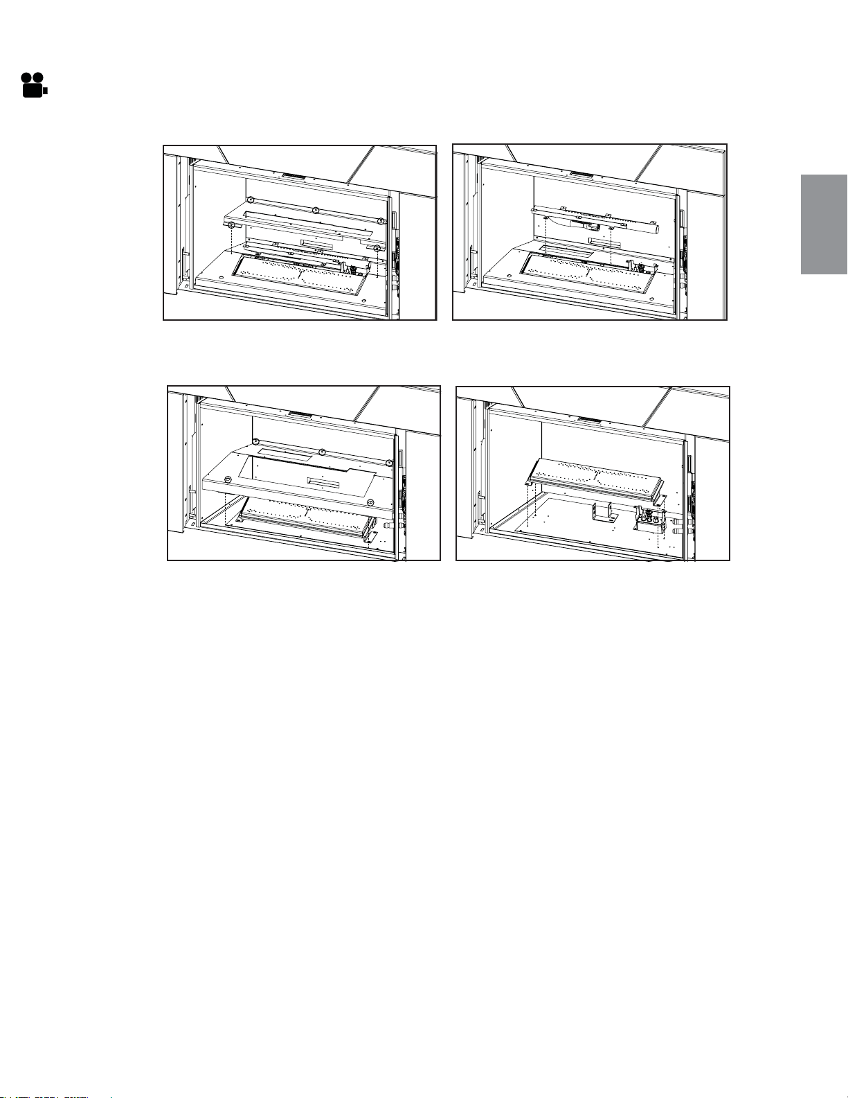
69
W415-1343 / A / 11.18.16
FR
8.5 ENLÈVEMENT DU BRÛLEUR
B. Retirez les 5 vis servant à fi xer le
support à bûche arrière. Soulevez le
support puis retirez-le.
C. Retirer les 4 vis servant à fi xer le
brûleur tubulaire arrière. Soulevez le
brûleur puis retirez-le.
D. Retirez les 5 vis servant à fixer le
support du brûleur avant. Soulevez
le support puis retirez-le.
E. Retirez les 4 vis servant à fi xer le
brûleur. Soulevez le brûleur puis
retirez-le.
A. Enlevez la porte vitrée, voir la section « ENLÈVEMENT ET INSTALLATION DE LA PORTE ».
Retirez les bûches, voir la section « FINITIONS ».
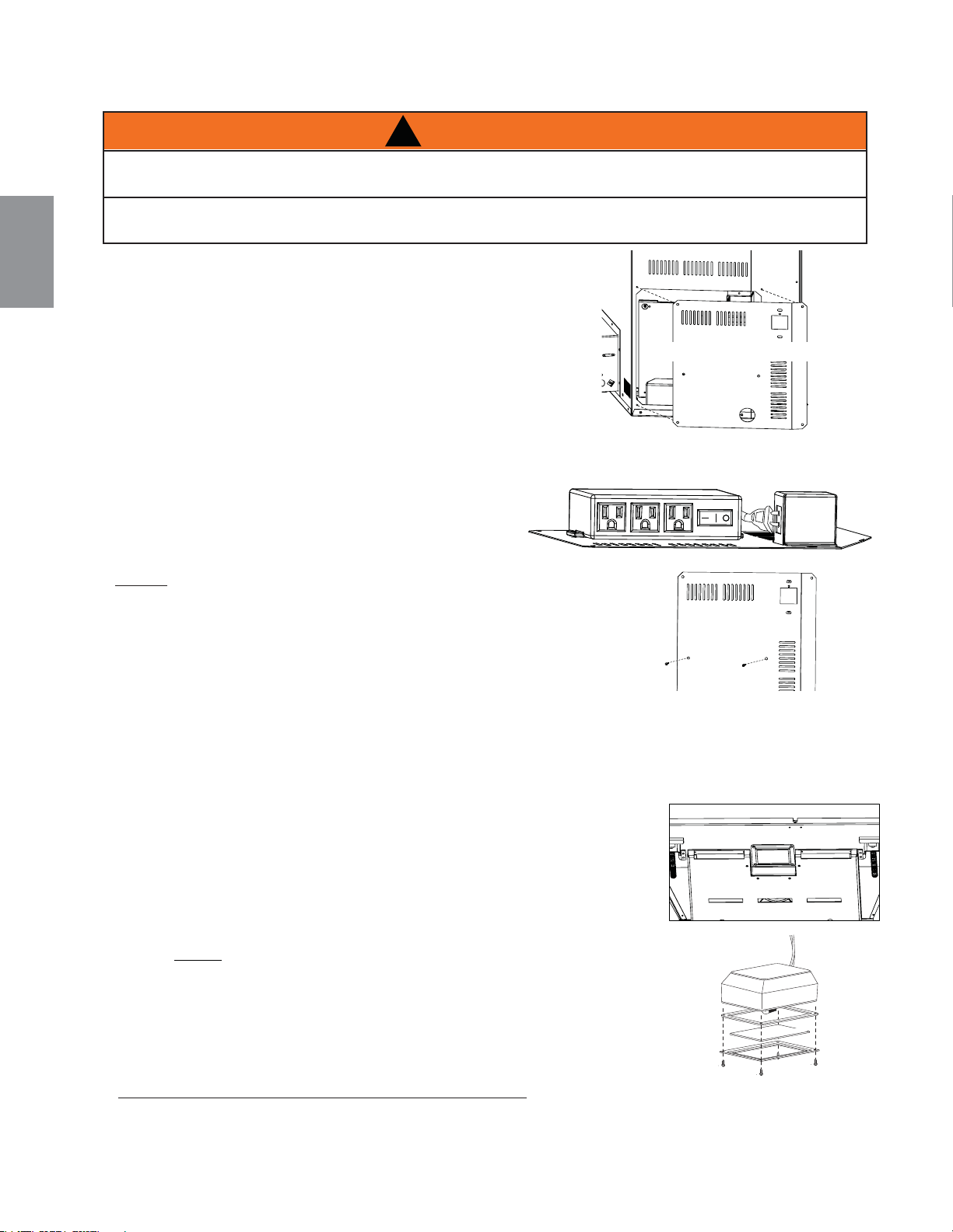
70
W415-1343 / A / 11.18.16
FR
8.6 REMPLACEMENT DU MODULE SOUFFLEUR
COUPEZ L’ALIMENTATION EN GAZ ET L’ALIMENTATION ÉLECTRIQUE AVANT DE PROCÉDER À
L’ENTRETIEN DE L’APPAREIL.
L’APPAREIL PEUT ÊTRE CHAUD. ATTENDEZ QU’IL SOIT REFROIDI AVANT D’EN FAIRE
L’ENTRETIEN.
!
AVERTISSEMENT
PANNEAU D'ACCÈS
A. Pour accéder au module de la souffl erie, vous devez
d'abord sortir l'appareil afi n d'allouer suffi samment
d'espace pour accéder au panneau d'accès gauche.
B. Enlevez les vis servant à fixer le panneau d'accès.
C. Débranchez le module de la soufflerie de la boîte
de dérivation. Débranchez la fiche de la lumière
de veille et la fiche de la soufflerie (s'il y a lieu) du
module de la soufflerie.
D. Retirez les 2 vis qui servent à fixer le module de
la soufflerie au panneau d'accès puis remplacer.
NOTE : Assurez-vous que l’interrupteur MARCHE/
ARRÊT soit à « ON » (-).
E. Réinstallez les fiches et le panneau d'accès.
8.7 REMPLACEMENT DE LA LUMIÈRES DE VEILLE
Votre appareil est muni d'une lumière de veille. La lumière de veille est précâblée et est contrôlée par la
télécommande
Si vous devez remplacer l’ampoule ou la lentille, suivez les instructions
suivantes.
A. Débranchez le module de la souffl erie de la boîte de dérivation situé
derrière le panneau d'accès gauche.
B. Retirez les quatre vis qui retiennent le cadre de la lentille. Ce
cadre retient la lentille de verre. Vous pouvez maintenant accéder
à l’ampoule.
NOTE: Ne manipulez pas l’ampoule à main nue; protégez-la avec un
linge propre et sec.
L’ampoule s’enlève en la tirant hors de la douille. Remplacez par des pièces Wolf
Steel uniquement, car l’ampoule et la lentille sont des produits spécialement conçus
pour les hautes températures. Lors de la réinstallation, vérifiez l’intégrité du joint
d’étanchéité.
LA CHAMBRE DE COMBUSTION DOIT ÊTRE SCELLÉE.
Le serrage excessif des vis risque de briser la lentille. Il est possible que des « fuites
de lumière » soient visibles au niveau de la zone supérieure. Les trous dans le boîtier de la lumière sont
nécessaires à la ventilation et ne doivent pas être couverts.
JOINT
D'ÉTANCHÉIT
É
LENTILLE
CADRE
CÔTÉ COLORÉ VERS LE HAUT
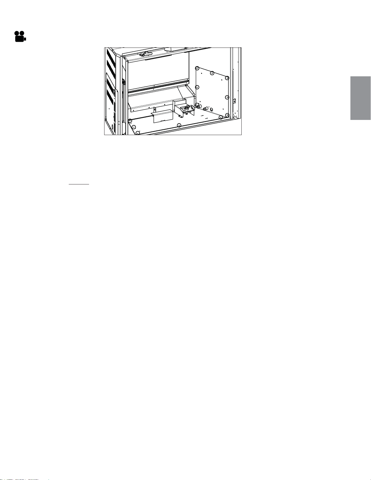
71
W415-1343 / A / 11.18.16
FR
8.8 REPLACEMENT DE L'ASSEMBLAGE DE LA SOUPAPE
A. Retirez la porte vitrée. Voir la section « ENLÈVEMENT ET INSTALLATION DE LA PORTE ». Retirez les
brûleurs, voir la section « ENLÈVEMENT DU BRÛLEUR ».
B. Retirez les 14 vis servant à fi xer l’assemblage de la soupape.
NOTE : Il est possible qu'un nouveau joint d'étanchéité soit nécessaire lors de la réinstallation de
l'assemblage de la soupape. Contactez votre détaillant local autorisé.
C. Soulevez l'assemblage de la soupape avec soin, suffi samment loin pour accéder à la soupape d'arrêt
manuelle puis tournez-la à « OFF ». Débranchez le raccord fl exible de la soupape. Vous pouvez
maintenant retirer l'assemblage de la soupape de l'appareil.

72
W415-1343 / A / 11.18.16
FR
9.0 RECHANGES
41.1C
Contactez votre détaillant pour les questions concernant les prix et la disponibilité des pièces de
rechange. Normalement, toutes les pièces peuvent être commandées chez votre détaillant autorisé.
POUR UN REMPLACEMENT DE PIÈCE SOUS GARANTIE, UNE PHOTOCOPIE DE LA
FACTURE ORIGINALE SERA REQUISE AFIN DE POUVOIR HONORER LA DEMANDE.
Lorsque vous commandez des pièces, donnez toujours l’information suivante :
• Modèle et numéro de série de l’appareil
• Date d’installation de l’appareil
• Numéro de la pièce
• Description de la pièce
• Fini
PIÈCES, NUMÉRO DES PIÈCES ET SI’IL SOIT DISPONIBILITÉ PEUT CHANGER SANS PRÉAVIS.
PARTIES IDENTIFIÉES COMME GARNIE SERONT LIVRÉS DANS 2 À 5 JOURS POUR LA
PLUPART DES DESTINATIONS DE LIVRAISON.
PIÈCES NON IDENTIFIÉES QUE STOCKÉS SERONT LIVRÉS DANS UN DÉLAI DE 2 À 4
SEMAINES POUR LA PLUPART DES CAS.
PIÈCES IDENTIFIÉES COMME « SO » SONT COMMANDE SPÉCIALE ET PEUVENT PRENDRE
JUSQU’À 90 JOURS POUR LA LIVRAISON.
OMETTRE DE POSITIONNER LES PIÈCES CONFORMÉMENT À CE MANUEL OU D’UTILISER UNIQUEMENT DES
PIÈCES SPÉCIFIQUEMENT APPROUVÉES POUR CET APPAREIL PEUT CAUSER DES DOMMAGES MATÉRIELS
OU DES BLESSURES CORPORELLES.
!
AVERTISSEMENT
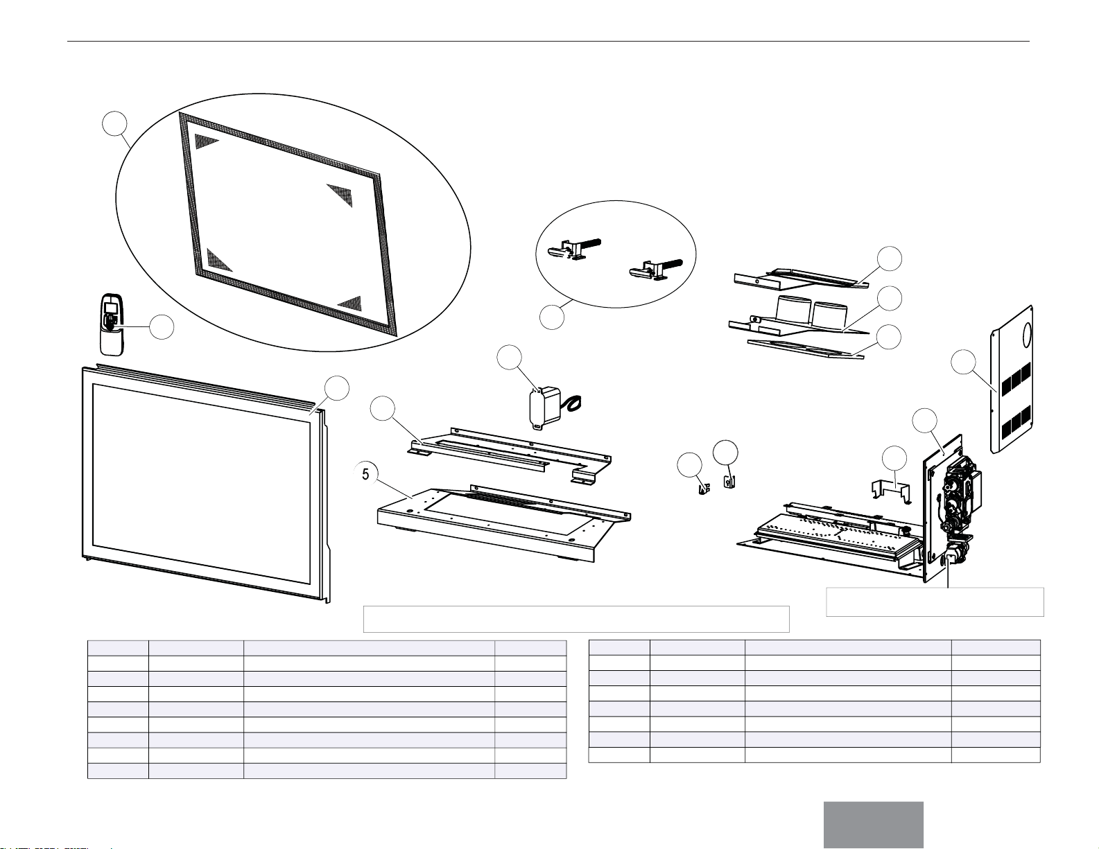
73
W415-1343 / A / 11.18.16
FR
13
6
9
8
7
14
5
4
15
3
11
10
13
6
10
9
8
14
7
5
15
4
12
11
REF. NO. PART NO. DESCRIPTION
EN STOCK
EN STOCK
1
2
3
4
5
6
7
8
REF. NO. PART NO. DESCRIPTION
POUR LES PIÉCES DE REMPLACEMENT
VOIR "L’ASSEMBLAGE DE LA SOUPAPE"
CES ARTICLES PEUT DIFFÉRER DE CELLE ILLUSTRÉ
1
12
3
9
10
11
12
13
14
15
W290-0183
W750-0191
W080-1222
W585-0751
W010-2648
W475-0792
JOINT D’ÉTANCHÉITÉ DES ÉVENTS
INTERRUPTEUR ACS
BOUCLIER DU VEILLEUSE
SUPPORT DE L’INTERRUPTEUR
L’ASSEMBLAGE DE LA SOUPAPE
PLAQUE D’ACCÈS ARRIÈRE
W010-2628
PLAQUE DE MONTAGE D’ÉVENTS
W660-0074
W010-2702
W200-0363
W200-0362
W010-2623
W660-0104
W010-2651
TÉLÉCOMMANDE MANUELLE
ASSEMBLAGE DE LA PORTE
COUVERCLE DU BRÛLEUR TUBULAIRE
ASSEMBLAGE DU LOQUET DE PORTE (X2)
RÉCEPTEUR
PLAQUE COULISSANTE
COUVERCLE DU BRÛLEUR PLATEAU
ENSEMBLE DE JOINT D’ÉTANCHÉITÉ
OUI
OUI
OUI
OUI
OUI
OUI
OUI
OUI
OUI
OUI
OUI
W562-0009
10.0 VUE D'ENSEMBLE
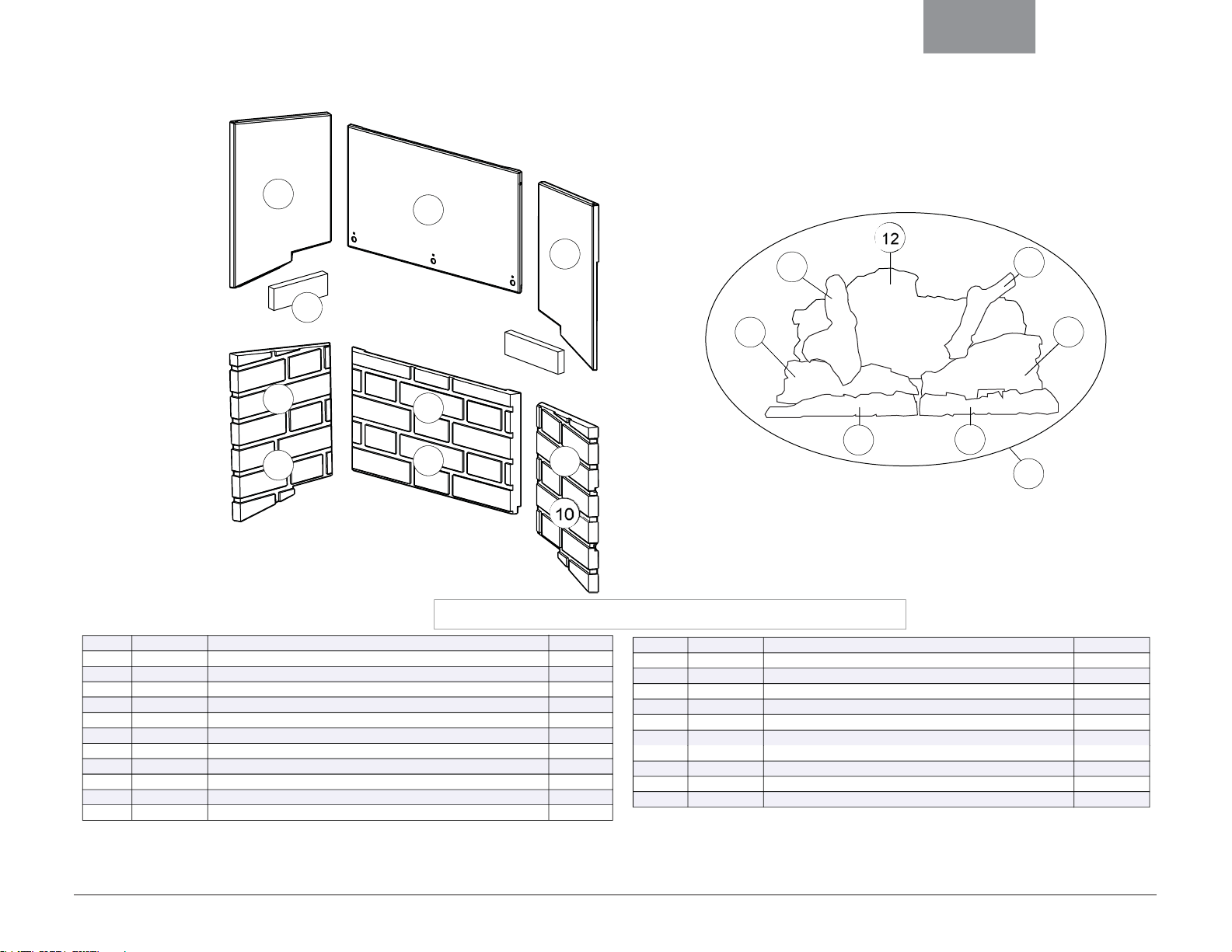
74
W415-1343 / A / 11.18.16
FR
11
W135-0468
1
9
6
2
10
7
3
1
16
1
14
1
11
112
1
13
1
15
1
17
18
REF. PART NO. DESCRIPTION
EN STOCK
EN STOCK
1 W500-0615
2 W500-0617
3 W500-0616
4
5
REF. PART NO. DESCRIPTION
6
7
8
9
PRP3
GI83 / GI85
8
5
4
10
W475-0797
W475-0799
W475-0798
W475-0815
W475-0813
W475-0814
GI83
GI85
W135-0465
W135-0471
W135-0470
W135-0467
W135-0466
W135-0469
GL-676
18
19
14
15
12
13
16
17
20
PRP3
21
CES ARTICLES PEUT DIFFÉRER DE CELLE ILLUSTRÉ
PANNEAU DE PORCELAINE DU CÔTÉ GAUCHE (PRP3) OUI
OUI
OUI
PANNEAU DE PORCELAINE DE L’ARRIÈRE (PRP3)
PANNEAU DE PORCELAINE DU CÔTÉ DROITE (PRP3)
NEW PORT PANNEAU DE BRIQUE DU CÔTÉ GAUCHE (GI83)
NEW PORT PANNEAU DE BRIQUE DE L’ARRIÈRE (GI83)
NEW PORT PANNEAU DE BRIQUE DU CÔTÉ DROITE(GI83)
ANGLAIS PANNEAU DE BRIQUE DU CÔTÉ GAUCHE(GI85)
ANGLAIS PANNEAU DE BRIQUE DE L’ARRIÈRE (GI85)
ANGLAIS PANNEAU DE BRIQUE DU CÔTÉ DROITE(GI85)
BÛCHE CROISÉ DROITE
BÛCHE DE L’ARRIÈRE
ENSEMBLE DE BÛCHES
W500-0668
PANNEAU DU CÔTÉ CERAMIQUE (X2) (PRP3)
PANNEAU DE BRIQUE DU NEWPORT
PANNEAU DE BRIQUE DU ANGLAIS
PANNEAUX RÉFLECTEUR RADIANTS EN PORCELAINE
BÛCHE CROISÉ GAUCHE
BÛCHE DU CÔTÉ DROITE D’AVANT
BÛCHE DE CHARBON CÔTE GAUCHE
BÛCHE DE CHARBON CÔTE DROITE
BÛCHE DU CÔTÉ GAUCHE D'AVANT
OUI
OUI
OUI
OUI
OUI
OUI
OUI
OUI
OUI
OUI
OUI
OUI
10.1 VUE D'ENSEMBLE (P. 2)
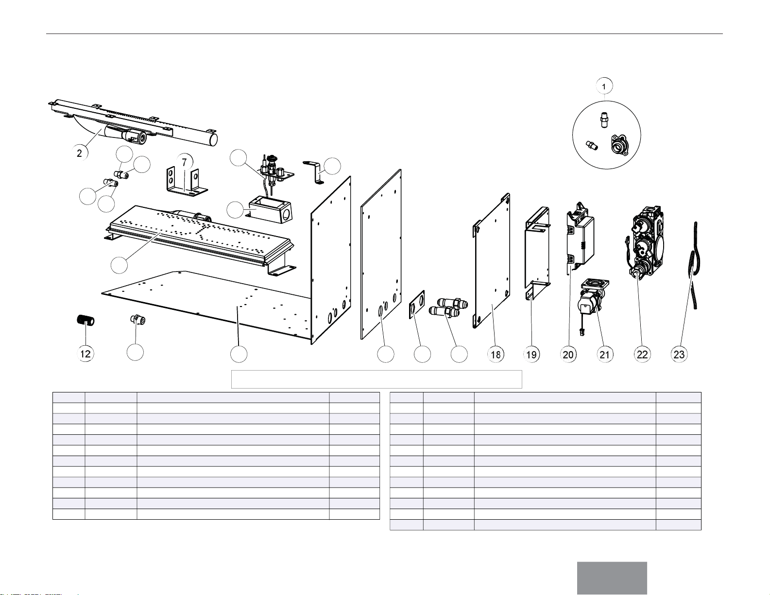
75
W415-1343 / A / 11.18.16
FR
4
2
1
12
9
7
8
6
1413
11
10
15 16 17 18 19 20 21
5
2
3
1
14
11
9
10
8
1615
13
12
17 18 19 20 21 22 23
W175-0338
REF. PART NO. DESCRIPTION
EN STOCK
EN STOCK
1 W175-0338
2 W010-2655 ASSEMBLAGE DE BRÛLEUR TUBULAIRE
3 W456-0053 INJECTEUR DE VEILLEUSE L’ARRIÉRE #53 (GN)
4 W456-0042 INJECTEUR DE VEILLEUSE L’AVANT #42 (GN)
5
6
7
8
9
10
11
REF. PART NO. DESCRIPTION
12
13
14
15
16
17
18
19
20
21
57
22
W456-0060
23
W456-0054
INJECTEUR DE VEILLEUSE L’ARRIÉRE #60 (P)
INJECTEUR DE VEILLEUSE L’AVANT #54 (P)
W710-0050
W290-0180
W500-0609
N255-0002
W585-0749
W080-1186
W190-0029
W725-0058
W725-0056
W010-1985
PLAQUE DE FIXATION
RACCORDS (X2)
SOUPAPE (ÉLECTRONIQUE)
W445-0022
W255-0002
W100-0133 PLATEAU DE BRÛLEUR
W080-1223
SUPPORT DE VEILLEUSE
W080-1305
SUPPORT DE TERRE DE LA VEILLEUSE
W010-2763
ASSEMBLAGE DE VEILLEUSE
W080-1189
SUPPORT DE L’INJECTEUR DE BRÛLEUR
46
4
CES ARTICLES PEUT DIFFÉRER DE CELLE ILLUSTRÉ
TROUSSE DE CONVERSION (P)
OUI
OUI
OUI
OUI
OUI
OUI
OUI
OUI
OUI
OUI
OUI
OUI
OUI
OUI
OUI
OUI
OUI
OUI
OUI
L'ASSEMBLAGE DU HARNAIS DE FILS
RACCORD TUBE 3/8 À RACCORD TUYAU 1/8
RACCORD NPT 3/8" x 2"
PLATEAU DE BRÛLEUR
PLATEAU DE BRÛLEUR JOINT D’ÉTANCHÉITÉ
PROTECTEUR DE CHALEUR
SUPPORT DU SOUPAPE
PANNEAU DE CONTRÔLE
SOUPAPE À SOLENOÏDE
10.2 L'ASSEMBLAGE DE LA SOUPAPE
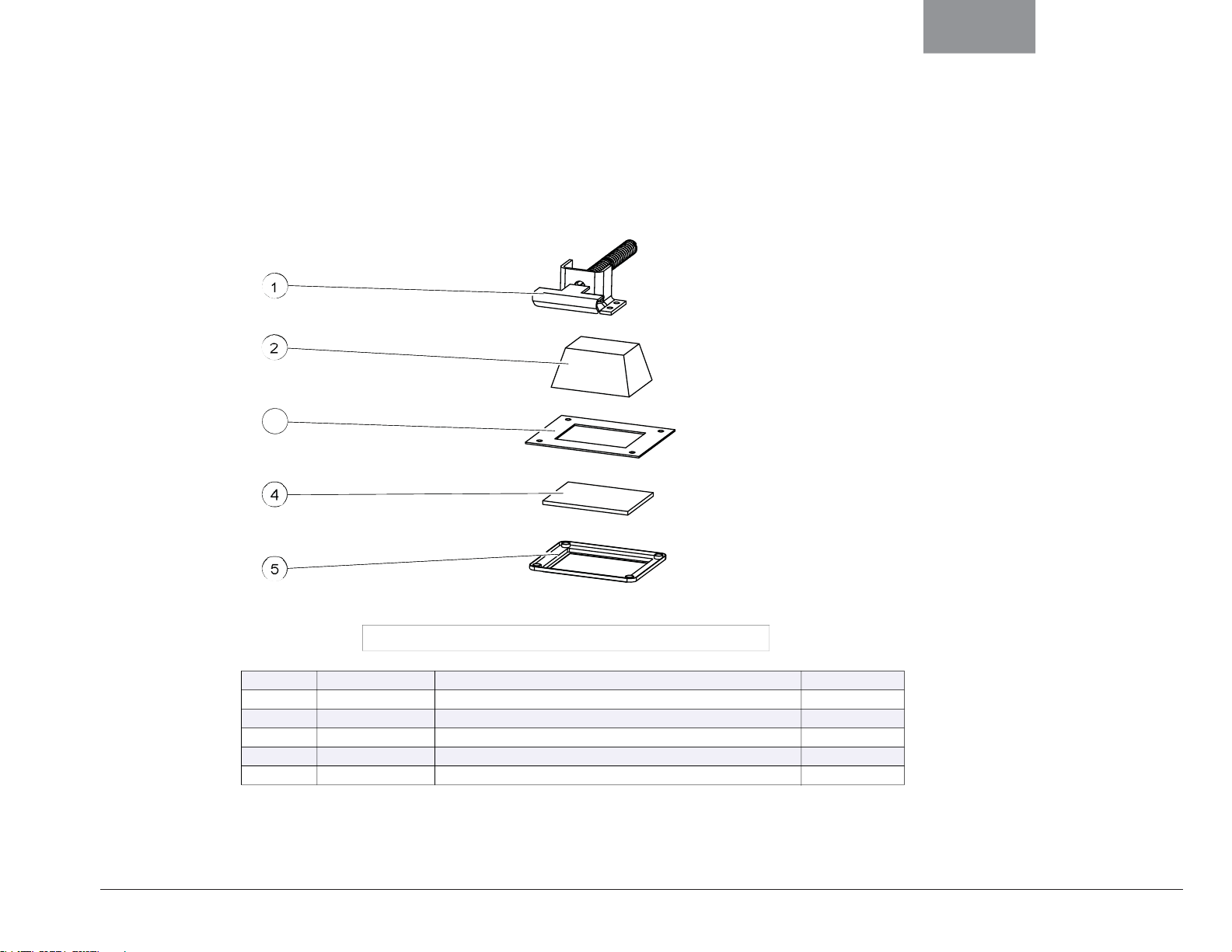
76
W415-1343 / A / 11.18.16
FR
6
5
4
1
3
5
4
3
1
2
NO. DE RÉF.
NO. DE PIÈCE DESCRIPTION
EN STOCK
1 W010-3684
2
3
N402-0001
4
W290-0080
5
W300-0067
W500-0288
LOQUET DE PORTE (X2)
ASSEMBLAGE DU LUMIÈRE À HAUTE TEMPÉRATURE
JOINT D’ÉTANCHÉITÉ PLAQUE DE RECOUVREMENT
VERRE CERAMIQUE LENTILLE
PLAQUE DE RECOUVREMENT LENTILLE
CES ARTICLES PEUT DIFFÉRER DE CELLE ILLUSTRÉ
OUI
OUI
OUI
OUI
OUI
10.3 L'ASSEMBLAGE DE LA CHAMBRE DE COMBUSTION
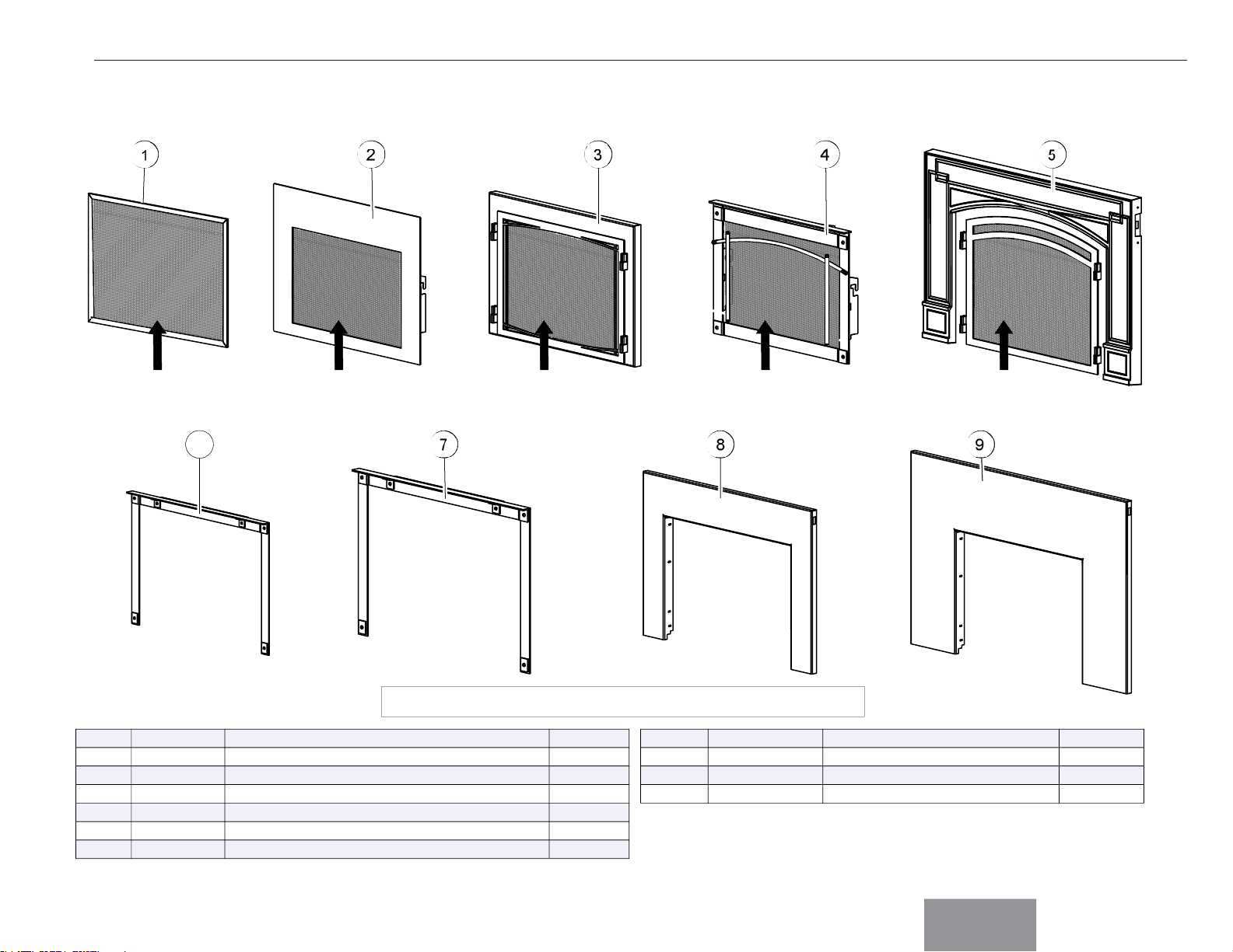
77
W415-1343 / A / 11.18.16
FR
1 53 4
1110
2
98
1 53 4
98
2
76
REF. PART NO. DESCRIPTION
EN STOCK
EN STOCK
1 W565-0133
2 I3CRF
3 I3DZ
4 I3DPS
5 CI3S
6
REF. PART NO. DESCRIPTION
7
8
I3FS6
9
I3FS9 CADRE DE PORTE EN GRANDE
W715-0891
W715-0905
I3FS6 I3FS9 I3DS6 I3DS9
L’ASSEMBLAGE DE
L’ÉCRAN DE PROTECTION
L’ÉCRAN DE PROTECTION L’ASSEMBLAGE DE
L’ÉCRAN DE PROTECTION
L’ASSEMBLAGE DE
L’ÉCRAN DE PROTECTION
L’ASSEMBLAGE DE
L’ÉCRAN DE PROTECTION
CES ARTICLES PEUT DIFFÉRER DE CELLE ILLUSTRÉ
L’ÉCRAN DE PROTECTION (I3SB)
OUI
OUI
OUI
OUI
OUI
OUI
AVANT RECTANGULAIRE DE CONTEMPORAIN
PORTE DU ZEN
CADRE DE PORTE EN ARTISAN
CONTOUR EN FONTE
CONTOUR EN PETITE (I3DS6)
CONTOUR EN GRANDE (I3DS9)
CADRE DE PORTE EN PETITE
11.0 ACCESSOIRES
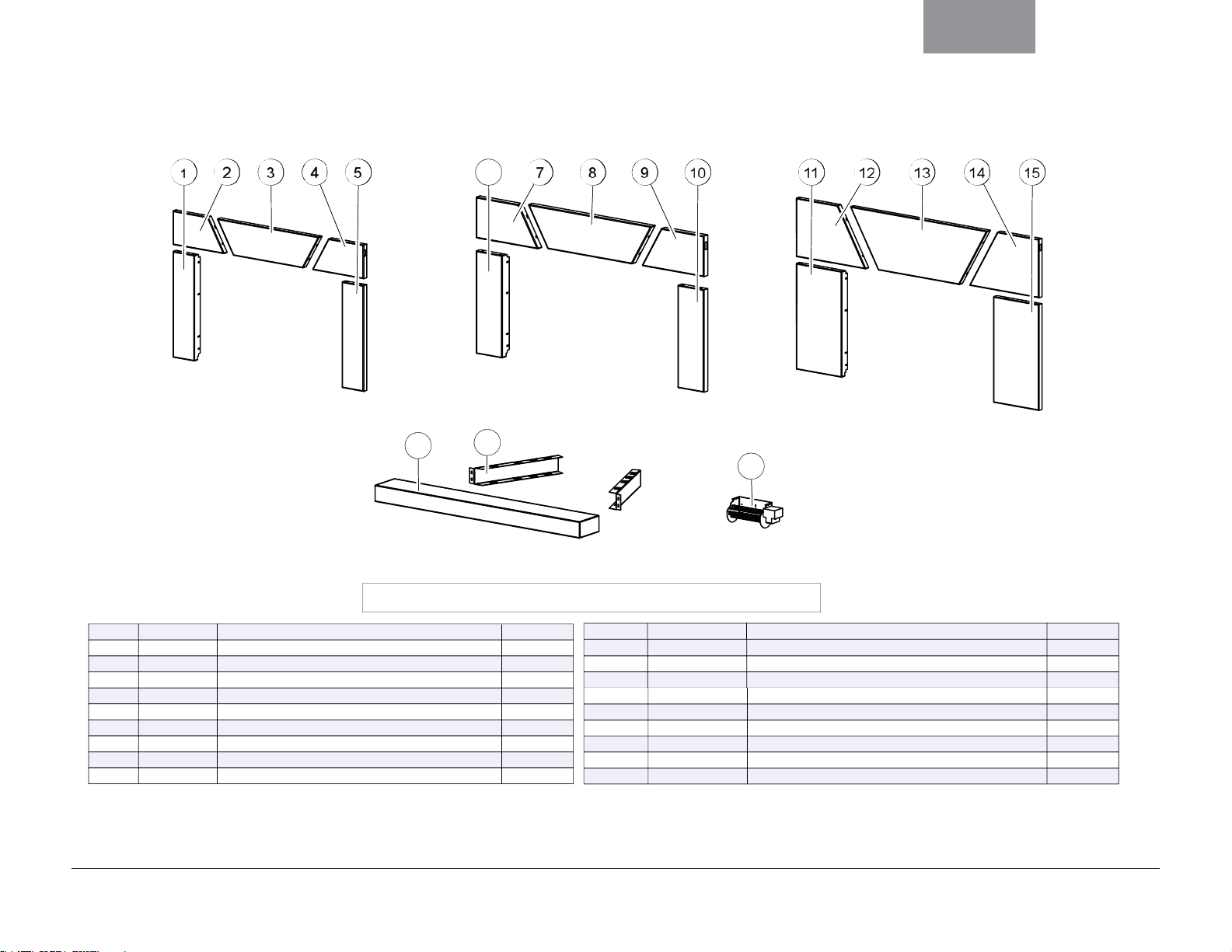
78
W415-1343 / A / 11.18.16
FR
6
7 8 9 101 2 3 54 11 12 13 1514
17
16
18
6
7 8 9 101 2 3 54 11 12 13 1514
17
16
18
I3S6
I3S9
I3S7
GI-RB
REF. PART NO. DESCRIPTION
EN STOCK
EN STOCK
1 W263-0121
2 W263-0120
3 W263-0119
4 W263-0118
5 W263-0117
6 W263-0172
7 W263-0169
8 W263-0170
9 W263-0168
REF. PART NO. DESCRIPTION
10 W263-0171
11 W263-0126
12 W263-0125
13 W263-0124
14 W263-0123
15 W263-0122
16 W715-0561
17 W525-0022
18 XI3BK
CES ARTICLES PEUT DIFFÉRER DE CELLE ILLUSTRÉ
CONTOUR, PIÈCE INFÉRIEURE GAUCHE (I3S6)
CONTOUR, PIÈCE SUPÉRIEURE GAUCHE (I3S6)
CONTOUR, PIÈCE CENTRALE (I3S6)
CONTOUR, PIÈCE SUPÉRIEURE DROITE (I3S6)
OUI
OUI
OUI
OUI
OUI
OUI
OUI
CONTOUR, PIÈCE INFÉRIEURE DROITE (I3S6)
CONTOUR, PIÈCE INFÉRIEURE GAUCHE (I3S7)
CONTOUR, PIÈCE SUPÉRIEURE GAUCHE (I3S7)
CONTOUR, PIÈCE CENTRALE (I3S7)
CONTOUR, PIÈCE SUPÉRIEURE DROITE (I3S7)
CONTOUR, PIÈCE INFÉRIEURE DROITE (I3S7)
GAUCHE INFÉRIEUR DE SOLIN (I3S9)
CONTOUR, PIÈCE SUPÉRIEURE GAUCHE (I3S9)
CONTOUR, PIÈCE SUPÉRIEURE CENTRALE (I3S9)
CONTOUR, PIÈCE SUPÉRIEURE DROITE (I3S9)
CONTOUR, PIÈCE INFÉRIEURE DROITE (I3S9)
BASE D’ÉLÉVATION (GI-RB)
RAILS (GI-RB) (X2)
SOUFFLERIE
11.1 ACCESSOIRES (P.2)
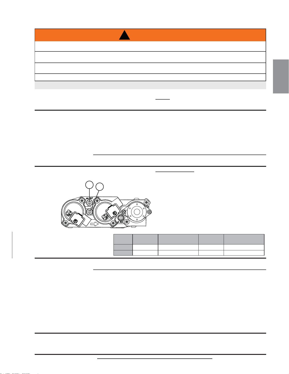
79
W415-1343 / A / 11.18.16
FR
12.0 GUIDE DE DÉPANNAGE
42.1C
SYMPTÔME PROBLÈME SOLUTIONS
La télécommande contrôle
les lumières Crystalite /
lumière de veille, mais il n'y a
aucune étincelle ou fl amme.
Le récepteur est
verrouillé.
- Réinitisalisez en fermant et en ouvrant l’alimentation.
NOTE : Si des piles de secours sont installées, elles
doivent aussi être retirées afi n de réinitialiser.
La fl amme du brûleur
principal est bleue,
paresseuse et
transparente.
Système d’évacuation
bloqué.
- Enlevez ce qui obstrue. Dans des conditions de froid
extrême, une accumulation de glace peut se former sur la
terminaison et devrait être enlevée lorsque nécessaire. Pour
minimiser les chances que cela survienne de nouveau, il
est recommandé que les évents qui passent à travers des
espaces non chauffés (greniers, garages, espaces réduits)
soient recouverts d’un manchon isolant en mylar. Assurez-
vous que le manchon ne puisse pas s’affaisser. Pour plus de
renseignements, contactez votre détaillant local autorisé.
Installation incorrecte. - Voir la section « ÉVACUATION » pour vérifi er le bon
emplacement des collets de solin.
Les fl ammes sont
régulièrement trop
grandes ou trop petites. Il
se produit des
dépôts de carbone.
La pression du gaz est
trop faible ou trop forte.
- Vérifi ez la pression : Pour vérifi er la pression d’arrivée,
tournez 2 ou 3 fois la vis (A) vers la gauche, puis emboîtez
le tube du manomètre sur la pointe d’essai. Le manomètre
doit indiquer la pression comme décrit sur le diagramme
ci-dessous. Assurez-vous que le brûleur principal fonctionne
à « HI ». La pression de sortie peut être vérifi ée de la même
façon en utilisant la vis (B). Le manomètre doit indiquer la
pression comme décrit sur le diagramme ci-dessous.
- Assurez-vous que le brûleur principal fonctionne à « HI ».
APRÈS AVOIR PRIS LA LECTURE DES PRESSIONS,
ASSUREZ-VOUS DE TOURNER FERMEMENT LES VIS
VERS LA DROITE POUR SCELLER. NE SERREZ PAS
TROP FORT. Vérifi ez pour des fuites en appliquant une
solution d’eau savonneuse.
-
Du carbone se dépose sur
la vitre, les bûches, les
roches, les composants
décoratifs ou les parois
de la chambre de
combustion.
Le volet d’air est
bloqué.
- Assurez-vous que l’ouverture du volet d’air n’est pas
bloquée par des fi bres ou autres obstructions.
La fl amme effl eure la
vitre, les bûches, les
roches, les composants
décoratifs ou les parois
de la chambre de
combustion.
- Vérifi ez si la vitre, les bûches, les roches et les
composants décoratifs sont positionnés correctement.
- Augmentez l’ouverture du volet d’air pour augmenter le
volume d’air primaire.
- Vérifi ez le débit d’alimentation : vérifi ez que la pression
du collecteur et la grandeur de l’injecteur soient telles que
spécifi ées sur la plaque d’homologation.
- Vérifi ez si les joints de la porte ne sont pas brisés ni
manquants et qu’ils sont étanches.
- Vérifi ez que les deux conduits d’évent ne soient pas troués
et qu’ils soient bien scellés à tous les joints.
- Vérifi ez si l’élévation minimale par pied (mètre)est
conforme pour toute évacuation horizontale.
Une pellicule blanche ou
grise se forme.
Le souffre du combustible
se dépose sur la vitre, les
bûches ou les parois de la
chambre de combustion.
- Nettoyez la vitre avec un nettoyeur recommandé. NE
PAS NETTOYER LORSQU’ELLE EST CHAUDE.
- Si vous ne nettoyez pas les dépôts régulièrement, la vitre
risque de rester marquée en permanence.
A
B
MAINTENANCE
MAINTENANCE
MAINTENANCE
ALLUMEZ TOUJOURS LA VEILLEUSE, QUE CE SOIT POUR LA PREMIÈRE FOIS OU LORSQUE
L’APPROVISIONNEMENT EN GAZ EST ÉPUISÉ, AVEC LA PORTE VITRÉE OUVERTE OU RETIRÉE.
COUPEZ L’ALIMENTATION EN GAZ ET L’ALIMENTATION ÉLECTRIQUE AVANT DE PROCÉDER À
L’ENTRETIEN DE L’APPAREIL.
L’APPAREIL PEUT ÊTRE CHAUD. N’EFFECTUEZ AUCUN ENTRETIEN JUSQU’À CE QUE L’APPAREIL
SOIT REFROIDI.
N’UTILISEZ PAS DE NETTOYANTS ABRASIFS.
!
AVERTISSEMENT
Pression
Gaz Naturel
(pouces)
Gaz Naturel
(millibars)
Propane
(pouces)
Propane
(millibars)
Arrivée *7” (min.4,5”) 17,4 mb (min.11,2mb) 13” (min.11”) 32,4 mb (min.27,4mb)
Sortie 3,5” 8,7 mb 10” 24,9 mb
*Pression d’alimentation
maximale ne devait pas
dépasser 13 po

80
W415-1343 / A / 11.18.16
FR
SYMPTÔME PROBLÈME SOLUTIONS
On détecte l’odeur
des gaz de
combustion dans
la pièce; maux de
tête.
L’appareil refoule les
gaz de combustion dans
la pièce.
- Vérifi ez tous les joints scellés de la porte.
- Vérifi ez si la cheminée ne serait pas bloquée.
- Vérifi ez que les conduits d’évents sont installés correctement.
- La pièce est sous pression négative; augmentez l’apport d’air frais.
La veilleuse ne
s’allume pas.
Il y a du bruit mais
aucune étincelle
au brûleur de la
veilleuse.
Filage.
- Vérifi ez si le fi l pour la sonde et le fi l pour l’allumeur
sont raccordés aux bonnes bornes (non inversés) sur
le module et l’assemblage de la veilleuse.
Connexion desserrée.
- Vérifi ez qu’il n’y a pas de connexions desserrées, de
courts-circuits dans le fi lage ou des contacts avec des
objets métalliques.
La longueur de l’étincelle
est incorrecte.
- La longueur de l’étincelle de l’allumeur à la veilleuse
devrait être de 0,125” (1/8” (3.2mm)).
La veilleuse ne
s’allume pas.
Aucun bruit et
aucune étincelle
au brûleur de
la veilleuse.
Les lumières
CrystalitesMC
et la souffl erie
fonctionnent.
Une connexion desserrée
ou causant un court-
circuit.
- Retirez et réinstallez le harnais de fils qui se branche dans le
module.
- Retirez et vérifiez la continuité de chaque fil dans le harnais de fils.
Le module n’est pas mis
à la terre.
- Vérifi ez si les assemblages de la veilleuse et de la soupape
sont bien mis à la terre au niveau du châssis du foyer.
La boîte d’allumage a
été verrouillée.
Choisissez l’une des quatre méthodes suivantes pour
réinitialiser le système.
1. Pour réinitialiser la boîte d’allumage lorsqu’elle a été
verrouillée, coupez l’alimentation électrique et retirez les
piles (s’il y a lieu) du récepteur.
2. Pour réinitialiser le tableau DFC lorsque celui-ci se trouve
en mode verrouillé et que la DEL clignote trois fois à l’aide
du bouton MARCHE/ARRÊT de l’émetteur:
Étape 1 : Éteignez le système en appuyant sur le
bouton MARCHE/ARRÊT.
Étape 2 : Après environ 2 secondes, appuyez de
nouveau sur le bouton MARCHE/ARRÊT de la
télécommande. Le tableau DFC se réinitialisera et la
séquence d’allumage s’enclenchera de nouveau.
3. Pour réinitialiser le tableau DFC lorsque celui-ci se trouve
en mode verrouillé et que la DEL clignote trois fois à l’aide
du cycle de fl amme :
Étape 1 : En mode de contrôle manuel de la fl amme,
utilisez la fl èche vers le bas pour éteindre la fl amme,
une situation indiquée par le mot « OFF » affi ché à
l’écran de la télécommande.
Étape 2 : Attendez environ 2 secondes et appuyez
sur la fl èche vers le haut; la séquence d’allumage se
déclenchera.
NOTE: En position « OFF », appuyez sur le bouton « ON » de la télécommande. Environ
4 secondes après que le bouton « ON/OFF » ait été enfoncé, le tableau d’allumage
commencera à produire des étincelles. Au premier essai, le tableau d’allumage formera des
étincelles pendant 60 secondes. S’il n’y a pas de correction de fl amme, le tableau cessera
de former des étincelles pendant environ 35 secondes. Après le temps d’attente, le tableau
démarrera le deuxième essai d’allumage en produisant des étincelles pendant environ 60
secondes. S’il n’y a toujours pas d’allumage, le tableau se verrouillera.
42.1_2A

81
W415-1343 / A / 11.18.16
FR
42.1_3B
SYMPTÔME PROBLÈME SOLUTIONS
Étincelle à la
veilleuse mais
celle-ci ne
s’allume pas.
Alimentation en gaz. - Vérifi ez si la soupape à bille de la conduite d’arrivée
du gaz est « Ouverte ». Vérifi ez si la pression
d’arrivée est dans les limites acceptables. La
pression d’arrivée ne doit pas excéder 14” de colonne
d’eau (34.9mb) .
Le module n’est pas mis
à la terre.
- Vérifi ez si les assemblages de la veilleuse et de
la soupape sont bien mis à la terre au niveau du
châssis métallique du foyer.
Plus de propane. - Remplissez le réservoir.
Continue de
produire des
étincelles et la
veilleuse s’allume
mais le brûleur
principal ne
s’allume pas.
Court-circuit ou conne-
xion desserrée dans la
tige de la sonde.
- Vérifi ez toutes connexions. Vérifi ez si les connexions
de l’assemblage de la veilleuse sont serrées; vérifi ez
aussi si ces connexions ne causent pas de mise à la
terre au niveau du métal.
Mauvais redressement
du courant de la fl amme
ou tige de sonde
contaminée.
- Vérifi ez si la fl amme enveloppe la tige de la sonde.
Ceci augmentera le redressement du courant de la
fl amme. Vérifi ez si le bon injecteur de veilleuse est
installé et que l’alimentation en gaz est conforme
aux spécifi cations du manuel. (Souvenez-vous que
la fl amme transporte le courant redresseur et non le
gaz. Si la fl amme se détache de la hotte, le circuit
est rompu. Un mauvais injecteur ou une pression
d’arrivée trop élevée peut causer la fl amme de
la veilleuse à se détacher.) La tige de la sonde a
possiblement besoin d’être nettoyée.
Mauvaise mise à la terre
entre l’assemblage de la
veilleuse et la soupape
de gaz.
- Vérifi ez si le harnais de fi ls est solidement branché
au module.
Veilleuse endommagée
ou tige de sonde salie.
- Vérifi ez si l’isolateur de céramique autour de la
sonde est craqué, endommagé ou desserré. Vérifi ez
la connexion de la tige de la sonde au fi l de la
sonde. Nettoyez la tige de la sonde avec une toile
d’émeri afi n d’enlever toute contamination qui ait
pu s’accumuler sur la tige de la sonde. Vérifi ez la
continuité avec un multimètre réglé sur Ohms au
calibre le plus bas.
La veilleuse a été peint
- Utilisant une pièce de papier de verre ou du tissu
d’émeri pour enlever le peinture du capuchon du
veilleuse, l’allumeur et le sonde de fl amme.
L’appareil
n’effectue aucune
fonction.
L’interrupteur du
récepteur est à la
mauvaise position.
- Vérifi ez que l’interrupteur du récepteur est en position
« REMOTE » (milieu).
Pas de puissance au
système.
- Vérifi ez que le disjoncteur est en position « ON ».
La télécommande ne
fonctionne pas.
- Vérifi ez les piles ainsi que leur orientation.
La lumière
de veille ou
la souffl erie
optionnelle ne
fonctionnent pas.
L’interrupteur du module
de contrôle est à la
mauvaise position.
- Vérifi ez que l’interrupteur « ON/OFF » est en position
« I », ce qui indique le fonctionnement.
L’interrupteur « COM »
est débranché.
- Vérifi ez que l’interrupteur « COM » est branché à
l’avant du module de contrôle.
82
W415-1343 / A / 11.18.16
FR
NAPOLÉON garantit ses produits contre les défauts de fabrication à l’acheteur d’origine seulement. L’enregistrement de la garantie n’est pas
nécessaire. Fournissez simplement une preuve d’achat ainsi que le modèle et le numéro de série afi n d’effectuer une réclamation de garantie.
NAPOLÉON se réserve le droit de demander à son représentant d’inspecter tous produits ou pièces avant d’honorer toute réclamation.
L’achat doit avoir été fait par l’entremise d’un détaillant NAPOLÉON autorisé et sous réserve des conditions et limitations suivantes :
La couverture de la garantie débute à partir de la date d’installation originale.
Cette garantie du fabricant n’est pas transférable et ne peut être prolongée ou étendue par aucun de nos représentants quelle qu’en soit la raison.
L’appareil au gaz doit être installé par un installateur autorisée qualifi é, une agence de service ou fournisseur. L’installation doit être faite
conformément aux instructions d’installation incluses avec le produit et à tous les codes d’incendie et de construction locaux et nationaux.
Cette garantie limitée ne couvre pas les dommages causés par un mauvais usage, un manque d’entretien, un accident, des altérations, des
abus ou de la négligence et l’installation de pièces d’autres fabricants annulera cette garantie.
Cette garantie limitée ne couvre pas non plus les égratignures, les bossellements, la corrosion ou la décoloration causés par une chaleur excessive, des
produits d’entretien chimiques et abrasifs ou l’écaillage des pièces en porcelaine émaillée, le bris par manipulation des bûches PHAZER
TM
et des braises.
NAPOLÉON garantit à vie ses brûleurs en acier inoxydable contre les défauts de fabrication et de matériau sous réserve des conditions
suivantes : durant les dix premières années, NAPOLÉON remplacera ou réparera selon notre option les pièces défectueuses gratuitement.
Après les dix premières années, NAPOLÉON fournira les brûleurs de rechange à 50% du prix de détail courant.
Au cours de la première année seulement, cette garantie s’applique à la réparation ou au remplacement des pièces garanties dont les
matériaux ou la fabrication sont défectueux à la condition que le produit ait été utilisé conformément aux instructions de fonctionnement et
dans des conditions normales.
Après la première année, concernant cette Garantie à Vie Limitée du Président, NAPOLÉON peut, à sa discrétion, se libérer entièrement de toutes
obligations en ce qui concerne cette garantie en remboursant à l’acheteur d’origine le prix de gros de toute pièce garantie qui est défectueuse.
NAPOLÉON ne sera pas responsable de l’installation, de la main-d’oeuvre ou autres dépenses relatives à la réinstallation d’une pièce garantie
et de telles dépenses ne sont pas couvertes par cette garantie.
Nonobstant toutes les dispositions contenues dans cette Garantie à Vie Limitée du Président, la responsabilité de NAPOLÉON sous cette
garantie est défi nie comme ci-dessus et elle ne s’appliquera à aucun dommage accidentel, consécutif ou indirect.
Cette garantie défi nit l’obligation et la responsabilité de NAPOLÉON en ce qui concerne l’appareil au gaz NAPOLÉON et toute autre garantie
énoncée ou implicite en ce qui concerne ce produit, ses composants ou accessoires est exclue.
NAPOLÉON n’endosse ni n’autorise aucun tiers à assumer en son nom, toute autre responsabilité concernant la vente de ce produit.
NAPOLÉON ne sera pas responsable d’une surchauffe, des refoulements, des déversements causés par des conditions environnementales
telles que des toits, des bâtiments, la proximité d’arbres, de collines, de montagnes, une ventilation ou des évents inadéquats, une
confi guration d’évacuation excessive, un apport d’air insuffi sant ou des pressions négatives qui peuvent ou non être causés par des systèmes
mécaniques tels que les ventilateurs d’évacuation, les fournaises, les sécheuses de linge, etc.
Tout dommage causé à l’appareil, à la chambre de combustion, à l’échangeur de chaleur, aux garnitures plaquées ou autres composants
par l’eau, les dommages causés par les intempéries, de longues périodes d’humidité, la condensation, des produits chimiques ou produits
d’entretien nuisibles ne seront pas la responsabilité de NAPOLÉON.
Toutes les pièces remplacées en vertu de la politique de Garantie à vie limitée du Président ne peuvent faire l’objet que d’une seule réclamation.
Durant les dix premières années, NAPOLÉON remplacera ou réparera les pièces défectueuses qui sont couvertes par la garantie à vie limitée
à sa discrétion gratuitement. Après les dix premières années, NAPOLÉON fournira les pièces de rechange à 50% du prix de détail courant.
Toutes les pièces remplacées au titre de la garantie seront couvertes pour une période de 90 jours à partir de leur date d’installation.
Le fabricant peut exiger que les pièces défectueuses ou les produits soient retournés ou que des photos numériques soient fournies pour
valider la réclamation. Les produits retournés doivent être expédiés port payé au fabricant pour une inspection en usine. Si un produit est
déclaré défectueux, le fabricant le réparera ou le remplacera.
Avant d’expédier votre appareil ou les pièces défectueuses, votre détaillant doit obtenir un numéro d’autorisation. Toute marchandise
expédiée à notre usine sans autorisation sera refusée et retournée à l’expéditeur.
Les coûts d’expédition ne sont pas couverts par cette garantie.Des frais de service supplémentaires peuvent être appliqués si vous cherchez
à obtenir des services au titre de la garantie auprès d’un détaillant.
Les indemnités de main-d’oeuvre au titre de la garantie s’appliquent uniquement pour le remplacement d’une pièce garantie. Les frais de
déplacement, de tests de diagnostic, d’expédition et autres frais afférents ne sont pas couverts par cette garantie.
2.1D
Les produits NAPOLÉON sont fabriqués conformément aux normes strictes du Certifi cat d’Assurance de la
Qualité mondialement reconnu ISO 9001 : 2008.
Les produits NAPOLÉON sont conçus avec des composants et des matériaux de qualité supérieure, assemblés par des artisans
qualifi és qui sont fi ers de leur travail. Le brûleur et le montage de la soupape subissent un test de détection de fuite et d’allumage
à une station de test de qualité. Une fois assemblé, chaque appareil est soigneusement inspecté par un technicien qualifi é avant
d’être emballé pour garantir que vous, le client, recevez le produit de qualité dont vous vous attendez de NAPOLÉON.
Les matériaux suivants et la fabrication de votre nouveau appareil au gaz NAPOLÉON sont garantis contre les défauts tant que
vous en êtes le propriétaire. Ceci couvre : la chambre de combustion, l’échangeur de chaleur, le brûleur en acier inoxydable, les
bûches Phazer
TM
et les braises, les roches, la vitre en céramique (cassure thermique seulement), les pièces plaquées or contre le
ternissement, les composants en porcelaine émaillée et les moulures d’extrusion en aluminium.*
Les composants électriques (110V et millivolt) et les pièces soumises à l’usure sont couverts et NAPOLÉON fournira gratuitement
les pièces de rechange durant la première année de la garantie limitée. Ceci couvre: la souffl eries, les soupapes de gaz, l’interrupteur
thermique, les interrupteurs, l’installation électrique, les télécommandes, l’allumeur, les joints d’étanchéité et l’assemblage de la veilleuse.*
Les coûts de main-d’oeuvre relatifs aux réparations garanties sont couverts gratuitement durant la première année. Cependant, les
travaux de réparation nécessitent l’approbation préalable d’un représentant autorisé de la compagnie. Les coûts de main-d’oeuvre
à la charge de NAPOLÉON sont basés sur un programme de tarifs prédéterminé et tout travail de réparation doit être accompli par
l’entremise d’un représentant autorisé NAPOLÉON.
* La fabrication de chaque modèle varie. La garantie s’applique uniquement aux composants disponibles avec votre appareil.
GARANTIE À VIE LIMITÉE DU PRÉSIDENT DES APPAREILS AU GAZ NAPOLÉON
CONDITIONS ET LIMITATIONS
TOUTES LES SPÉCIFICATIONS ET LES CONCEPTIONS SONT SUJETTES À MODIFICATIONS SANS PRÉAVIS EN RAISON DES
AMÉLIORATIONS CONSTANTES APPORTÉES AUX PRODUITS. NAPOLÉON EST UNE MARQUE DE COMMERCE DÉPOSÉE DE
WOLF STEEL LTÉE.
13.0 GARANTIE
83
W415-1343 / A / 11.18.16
FR
Date
43.1A
Problèmes particuliersTravail effectuéNom du technicienDétaillant
Historique d’entretien de l’appareil
Cet appareil doit être entretenu annuellement selon son usage.
14.0 HISTORIQUE D’ENTRETIEN
"VUSFTQSPEVJUT/BQPMÏPO
®
'PZFSTFODBTUSÏTt(SJMTBVDIBSCPOEFCPJTt'PZFSTBVHB[t$BTDBEFTEFBV
1PÐMFTËCPJTt1SPEVJUT)7"$t'PZFSTÏMFDUSJRVFTt'PZFSTFYUÏSJFVSTt(SJMTËHB[EFRVBMJUÏ
'PZFST$IBVGGBHFFU$MJNBUJTBUJPO(SJMTDPNQPTF[
napoleonproducts.com
3PVUF5SBOTDBOBEJFOOF.POUSÏBM2VÏCFD)5"
/BQPMFPO3PBE#BSSJF0OUBSJP$BOBEB-.(
#BZWJFX%SJWF#BSSJF0OUBSJP$BOBEB-/:
.JMMFS%SJWF$SJUUFOEFO,FOUVDLZ64"