1 2 3 4
External Sensor
1 2
3 4
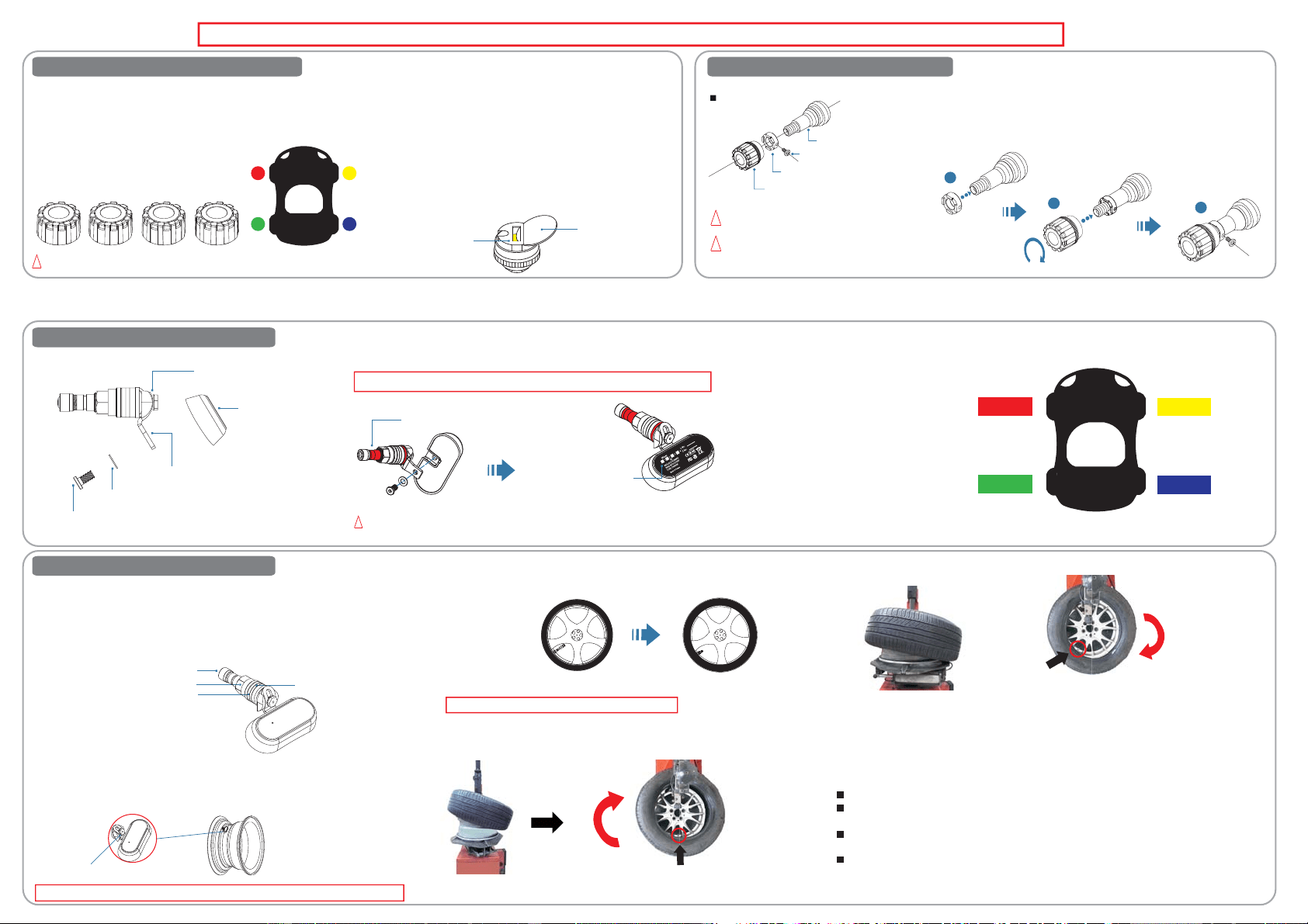
During sensor installation please check and make sure there are no cracks or aging on the tyre valve, and should be checked regularly to enhance driving safety.
1.
The installation of tire pressure sensors
Battery spring
Coin / Metal object
!
Make sure sensor body does not mix up with other sensor cap.
As each sensor has its own position, you have to make sure it’s in the
pre-set position. When inserting batteries in every sensor, please
don’t mix up sensor caps and every sensor has their own positions.
Please check the sensor map for guidance for user to install.
(1) means “ Front Left Tire ”.
(2) means “ Front Right Tire”.
(3) means “ Rear Left Tire ”.
(4) means “ Rear Right Tire ”.
Note:
Due to the sensor consuming very small battery power, so that the
remaining battery power could be retained for some time. In the event
the sensor resets or causes malfunctions, battery replacement may be
recommended. Power will need to be discharged from the sensor,
please follow these steps:
A. Use a metal object, such as coins, keys... etc., insert into the sensor
at the same time touching the battery metal holder and yellow color
area (battery holders negative), to achieve the power discharge. As
shown in the photo.
B. Then re-insert the new CR1632 lithium battery into sensor.
2.
Anti-theft tool for sensor (Optional)
Valve
Anti-theft fixed ring
Hex socket screw
Sensor
Part location A. Place the ring on the valve.
B. Install the sensor ( turn 5~7 times).
C. Use hex key to tight anti theft ring ( torque 0.71kg-cm (6.95N.cm)) make
sure the ring is not loose.
A
B
C
!
Screw and ring tighten distance is 0.7mm.
!
Make sure the screw is facing outward.
※ Hex key size:ψ2.5mm
Internal Sensor (Not Available in Australia/New Zealand)
1.
The installation of INTERNAL sensors
Insert disc-shaped washer into the hex socket cap screws, then assemble
the valve nozzle with sensor body and tight it with hex key. (Recommended torque
is around 1.7N•m)
!
Please verify the internal type sensor position and the valve stem color to avoid
Mistransplant.
As each sensor has its own position and color, you have to make sure its pre-set position. Every sensors have
own positions and sensors map could give guidance for user to install.
Red means “ Front Left Tire ”.
Yellow means “ Front Right Tire ”.
Green means “ Rear Left Tire ”.
Blue means “ Rear Right Tire ”.
Red
Yellow
Green
Blue
After complete installation, please make sure the Hex socket cap screws is tight.
Hex socket cap screws
Disc-shaped washer
Air valve nozzle accessories
Sensor body
Screw for the valve nozzle
Relative wheel position
Red→1、Yellow→2
Green→3、Blue→4
Valve stem color
(Red、Yellow、Green、Blue)
A. Disassemble the wheel from the car.
B. Deflate the disassembled wheel.
C. Use tire changer to take apart the tire and rim.
D. Take out the old valve from rim.
E. Screw off the Valve cover, rim nut, plastic spacer and Rubber O
ring on the sensor.
F. Use a open-end 7mm wrench to loose the valve nozzle screws, and
then follow the instruction photo below to insert the sensor to a proper
location on the rim, and adjusted to the proper angle, and then tighten
the valve screw. (Recommended torque is around 1.7N•m)
2.
The installation of INTERNAL sensors
After complete installation, please make sure the screw for the valve nozzle is tight.
Valve cover
rim nut
plastic spacer
Rubber O ring
Screw for the valve nozzle
G. Fix the sensor on the rim by screwing the rim nut onto the sensor. Do not
use destructive force to fix the rim nut for protection from damage. (Never
use excessive force to avoid damage to the sensor recommended torque
is around 0.9N•m)
H. Install the tire on the rim steps are as following
(1) Place the sensor on tyre remover machine and to adjust the position of
the rotating platfrom on the 6 o'clock position then install the tire
properly in clock wise direction. As the picture shown.
Sensor location should be
in around 6 o'clock position
Wheel rotational
direction
Installer stand location
Precaution: avoid the tire bead touching the sensor.
Note:
It is necessary to ask for the assistance from a professional for the tire installation.
It needs to adjust the tire position to fit or disassemble the tire, so that the sensor can be kept
away from the running location of the tire changer to prevent any damages on the sensor.
Every sensor has its separately specific marking for different tire position, please make sure to
install the sensor to each tire in order.
The sensor is an electronic detector powered by a lithium battery. If there is insufficient power in the
sensor, the sensor will send back insufficient power code tothe receiver module. If the power is
insufficient, need to replace a new sensor to ensure the normal operation of the system to update the
correct tire information.
(2) Refitting the tire bead, please place the sensor approximately 7 o’clock position as the picture
shown.
Wheel rotational
direction
Sensor location should be
in around 7 o'clock position
Installer stand location
I. Use tire changer to fit the tire on the rim, then inflate the tire with standard tire pressure, so monitor
will show the real time tire pressure value.
J. Spray soap water around the valve stem area to check for air leakage.
K. Make balancing testing and correcting for wheel on the balancing machine.
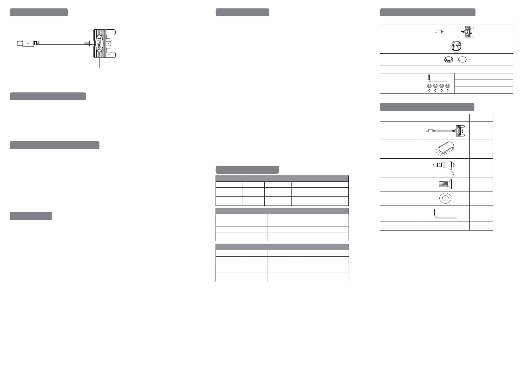
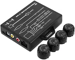
Signal Input Terminal
Receiver module body
Power Input Connector
Antenna
1.
Location of outlook
2.
Sensor runs out of battery
3.
Setting Advanced - Learning mode
4.
Precautions
A. Due to rubber valve stem aging under high temperature and expose under the sun, which may cause crack
on the rubber stem, therefore, we recommended metal type of valve stem.
B. Please double confirm if sensors are fitted tightly. If necessary, please spray soapy water on the valve stem
to check any air leakage.
C. If tire pressure is getting down or dropping quickly, please stop car immediately to find out if tire is deflated
or another problem is happening.
D. Please make sure if your sensor has mixed with other systems. As each sensor has its unique identified
number and monitor can only receive pre-loaded identified number and cannot accept other new identified
number.
E. The external sensor battery is lithium battery CR1632, please select the correct model. Lithium battery
caution:
(1) Do not clip with metal object.
(2) Can not swallow, recharge or throw into fire.
F. Please do not operate this device while you’re driving.
5.
Trouble Shooting
A. Indications disappear from / do not appear in the MiVUE display
(1) There is a certain limit transmitting range between sensor and module. Please
confirm if the sensor is within the receiving range.
(2) Be sure to observe the correct polarity when installing the batteries.
(
3) When the sensor battery is out of power, under long period of usage. It
is recommended to replace new battery for external type sensor.
(4) Reinstall the sensor battery. After removing the sensor battery, conduct discharge
process to the sensors, this purpose is to reset the sensor.
(5) Please make sure if your sensor has mixed with other systems’. As each sensor has
its unique identified number and monitor can only receive pre-loaded identified
number and cannot accept other new identified number.
(6) The receiver module is recommended to install on an open space such as a
windshield to get the best signal reception.
B. Receiving module without signal
Receiving module needs to be used with MiVUE DVR.
C. Many environmental factors cause tire pressure rise and drop as well. For example, hot
weather or warm tire will lead rising tire pressure.
D. Sensor temperature difference
Running engine, exposure under the sun, constant braking or near high temperature
and other factors, can easily make sensor heat conditions inconsistent and cause the
difference in temperature measurement.
(Please ensure you set your temperature pressure limit to factor in for changes from
cold to hot temperature. If you are unsure of your tyre's cold and hot temperature
pressure recommendations, please check your vehicles user manual.)
E. If these solutions do not help improve the situation, consult your nearest dealer.
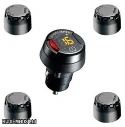
Receiver Module Description
Receiver Module
Receiver
Sensor body
User guide
Hex key
Air valve nozzle
accessories
Hex socket
cap screws
Disc-shaped washer
※Specifications are correct at time of publication. Subject to change without notice.
7.
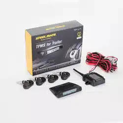
Product Package Content - External
Anti-theft tool
Spanner
Anti-theft fixed ring
Hex socket screw
1 piece
User guide
Items Content Quantity
Tire pressure sensor
CR1632
lithium battery
4 pieces
4 pieces
4 pieces
4 pieces
1 piece
1 piece
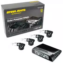
8.
Product Package Content - internal
Items
Content Quantity
1 piece
1 piece
4 pieces
4 pieces
4 pieces
4 pieces
1 piece
The sensor is an electronic detector powered by a lithium battery. If there is insufficient power in the sensor, the
sensor will send back insufficient power code to the receiver module. If the power is insufficient, the external
sensor recommends to replace the lithium battery to ensure the normal operation of the system to update the
correct tire information.
This feature is mainly supplied to the solution when the sensor is missing. Because the monitor can only identify
the same ID group of sensors, other sensors can’t be read, then just order a new sensor and
re-learning the new sensor.
A. First, install the sensor on the tire.
B. The receiver module is connected to the DVR power is remained and the DVR is with power on.
C. Switch the DVR to "learning mode setting" which will enter the receiving mode for new sensor signal.
D. Under the learning mode if the sensor signal input, you can re-identify the new sensor. The recommended
practice is to reinstall the sensor battery to ensure that the signal is sent immediately.
E. After learning, the DVR inputs "confirm" command to the receiving module to exit from the receiving mode.
External Sensor
433.92MHz 3Volts DC
433.92MHz 5Volts ~ 12Volts DC
-20℃ ~ 80℃
433.92MHz
0 ~ 60PSI
-40℃ ~ 125℃
43°
30m
6.
Product Specification
Diameter 20.8mm x Height 22.7mm
13g (±1)
-40℃ ~ 125℃
Pressure range
Pressure accuracy ±1PSI
0 ~ 60PSI
±2℃
Temperature
accuracy
Dimensions
Weight
Operating
temperature
Operating voltage
Angle adjustable
valve stem
36.9g (±1)
Frequency
Pressure range
Pressure accuracy ±1PSI
±2℃
Temperature
accuracy
Dimensions
Weight
Operating
temperature
Length 60.4mm × Width 27.6mm ×
Height 11.7mm
Internal Sensor
Frequency
Frequency
Operating
temperature
Operating voltage
Dimensions
Length 45mm × Width 40.8mm ×
Height 11.5mm
Weight 13.5g (±1)
Receiver Module
Effective
receiving distance