Version 1.0
FOR PGH INVERTER SERIES
MONITORING
SCREEN
01
Disclaimer
The manufacturer accepts no liability for any damage caused by:
This manual contains important installation and operation
instructions for your Renogy monitoring screen. Please review
and observe these instructions and keep them located near the
monitoring screen for further reference. The following symbols
are used throughout the manual to indicate potentially
dangerous conditions or important safety information.
Intentional or accidental misuse, abuse, neglect or improper
maintenance, and use under abnormal conditions.
Improper installation, improper operation, and malfunction of
a peripheral device.
Contamination with hazardous substances, diseases,
vermin, or radiation.
Alterations to the product without express written consent
from the manufacturer.
Must be properly ventilated to ensure no build-up of
explosive gases prior to installation.
Force majeure: including fire, typhoon, flood, earthquake,
war, and terrorism.
Important Safety Instructions
Please save these instructions.
Indicates a potentially dangerous condition.
Use extreme caution when performing this task.
Indicates a critical procedure for the safe and proper
installation and operation of the monitoring screen.
Indicates a procedure or function that is
important to the safe and proper installation and
operation of the monitoring screen.
NOTE
CAUTION
WARNING

02
General Safety Information
Inverter Safety
Installation and wiring must comply with the Local and
National Electric Codes (NEC) and must be done by a
certified technician.
Read all the instructions and cautions in the manual before
beginning the installation. There are no serviceable parts for
this inverter.
Do NOT disassemble or attempt to repair the monitoring screen.
Make sure all connections going into and from the inverter
are tight. There may be sparks when making connections,
therefore, make sure there are not flammable materials or
gases near installation.
The inverters are suitable for 12V Battery Banks ONLY.
ALWAYS make sure inverter is in OFF position and
disconnect all AC and DC connections when working on any
circuit associated with the inverter.
NEVER connect the AC output of the unit directly to an
Electrical Breaker Panel/ Load Centre which is also fed from
the utility power / generator.
When connecting battery terminals, ensure the polarity of the
battery connections is correct. Incorrect polarity may cause
permanent damage to the unit.
Be careful when touching bare terminals of capacitors as
they may retain high lethal voltages even after power is
removed.

03
The monitoring screen is designed for indoor/compartment
installation. DO NOT expose it to direct sunlight, rain, snow,
moisture, or liquids of any type.
DO NOT puncture, drop, crush, burn, penetrate, or strike the
monitoring screen.
The monitoring Screen is only compatible with Renogy PGH
Inverter Series. DO NOT attempt connecting the monitoring
screen to other inverters or systems.
The RMS-PGH will operate when the PGH Inverter is in the
ON or REM position. Only in the REM position, will the
RMS-PGH be able to manually turn the inverter ON/OFF in
addition to monitoring the inverter.
Changing the frequency (50/60Hz) or the power mode
(Normal/Eco) will need to be done physically on the inverter.
The inverter then needs to be rebooted for the changes to
take effect on the monitoring screen.
In order to read the parameters of the inverter correctly,
1. The switch must be in the ON or REM position and the
COMM port correctly connected to the RJ45 cable.
2. The REMOTE port is correctly connected to the RJ12
communication cable.
DO NOT open, dismantle, or modify the monitoring screen.
Monitoring Screen Safety

Table of Contents
01
05
06
06
09
07
15
16
16
16
17
17
18
19
19
21
15
04
Important Safety Instructions
General Information
Product Overview
Identification of Parts
Dimensions
Installation
Operation
LCD User Interface: Overview
Voltage (V)
Current (A)
Watts (W)
Frequency (Hz)
Error Code
Normal / ECO Mode
LED Indicators
Troubleshooting
Technical Specifications

05
General Information
Comprehensive Protection
Easy Operation
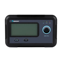
The RMS-PGH is a high precision meter designed for PGH
series pure sine wave inverters. Featuring a backlit display and
flush-mountable, it is engineered for an aesthetically clean and
professional look on RVs or camper walls. Utilize the 2-key
input to easily navigate through your system information as
well as identify any error codes. In addition, use the power
button to manually shut down the inverter at your convenience.
The RMS-PGH is the perfect monitor companion to optimize
any solar system!
Plug and Play
Simply connect the monitoring screen to the PGH inverter
using an RJ12 and RJ45 communication cable for real-time
monitoring.
Accurate Readings
Obtains input and output readings directly from the
communication port on the inverter.
Simply connect it to your inverter and let the screen take
care of the rest.
Displays inverter error codes for quick identification of
abnormal conditions or improper operation
Key Features
06
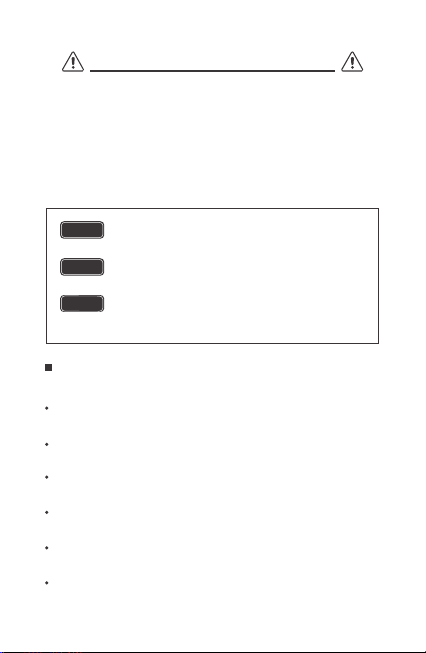
Product Overview
LCD Screen
Input/output
Parameter Switch Key
Main On/Off power key
LED Status Lights
Front Cover Plate
Mounting Holes
RJ45 Communication Port
RJ12 Communication Port
①
②
②
③
③
④
④
⑤
⑥
⑤
⑥
⑦
⑦
⑧
⑨
⑧
Identification of Parts
①
⑨
RMS-PGH
ON ELEC ERR
07
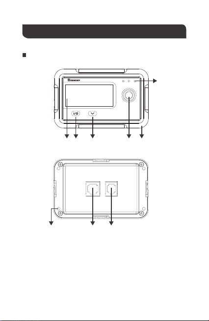
Dimensions
110.0mm
4.3in
87.5mm
3.4in
1.3in
0.8in
2.8in
70.0mm
2.3in
58.5mm
31.8mm
19.5mm
RMS-PGH
ON ELEC ERR
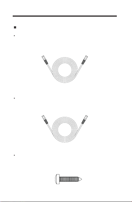
Additional Components
RJ45 Communication Cable
The RJ45 Communication Cable (5m/16.4ft) is used to connect
the monitoring screen to the "COMM" port for data transmission.
The RJ12 Communication Cable (5m/16.4ft) is used to connect
the monitoring screen to the "REMOTE" port for power supply.
RJ12 Communication Cable
Self-tapping Screws (4)
The Self-tapping Screws (M2.9*13mm) are used to fix the
monitoring screen on the mounting surface.
08

09
BEFORE drilling, make sure there are no electrical component
or other obstacles that may interfere with installation on the
other side of the mounting surface.
Before installation, check to make sure the power is working
properly. Resolve any issues before installation of monitoring
screen and cable.
The following are recommendations for installation. There will
be multiple mounting methods depending on users’ applications.
The RMS-PGH requires a flush mount installation. The
RMS-PGH’s faceplate will be flush with the mounting surface
and the body of the meter.
CAUTION
WARNING
Please choose a clean, dry, protected and easily accessible
indoor location to install the monitoring screen. It is
recommended to mount the monitoring screen at eye level for
easy access to the battery information and operation buttons.
The RJ45/RJ12 Communication ports on the monitoring screen
are accessible from the back of the unit. Clearance of at least 2
inches (50 mm) behind the unit is recommended to allow for the
bending radius of the RJ45/RJ12 Communication Cables that
connect to the monitoring screen.
Before installing the monitoring screen, it is recommended to
have the following tools available:
Installation
Preparation
Choosing an Installation Location
Pencil Drill Jigsaw Phillips screwdriver
NOTE
10
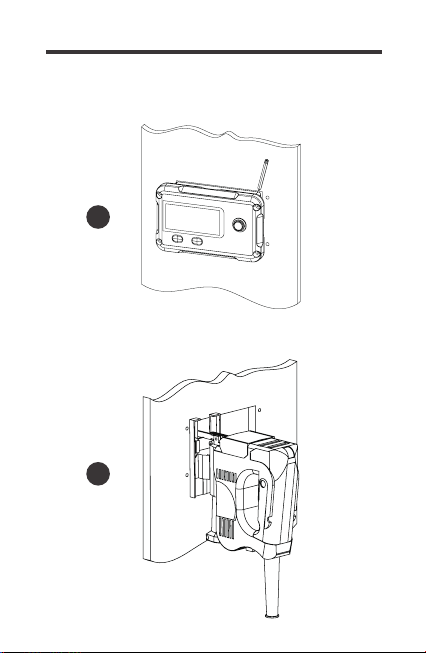
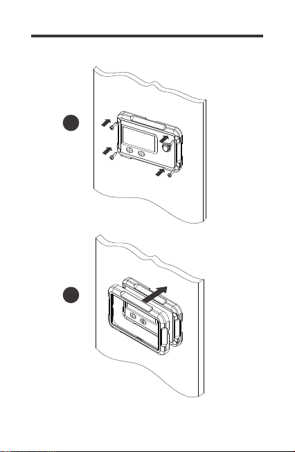
Use the monitoring screen as a template to mark the screw
holes and trace the cut-out area on the mounting surface
with a pencil.
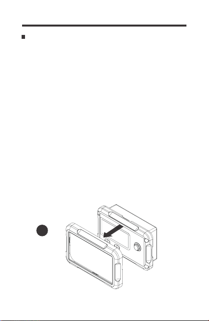
Remove the snap-fit Front Cover Plate from the monitoring
screen.
Mounting the Monitoring Screen
1
2.
Cut out a rectangle area for the monitoring screen on the
mounting surface with a jigsaw. You may also use the cut out
dimension specified after Step 2.
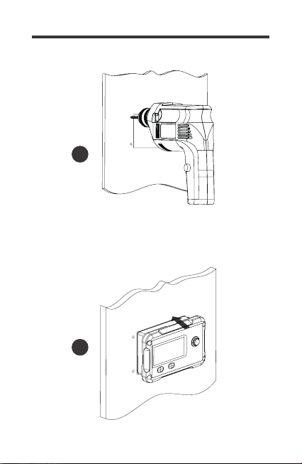
3.
Pre-drill four screw holes on the mounting surface with a drill.
4.
Place the monitoring screen into the cut-out area and align
the mounting holes on the monitoring screen with the
pre-drilled screw holes.
5.
Affix the monitoring screen on the mounting surface with the
included four self-tapping screws.
6.
Re-attach the snap-fit Front Cover Plate to the monitoring
screen.
7.
1.
11
3
2
12
Cutout Dimensions
(L x H x W): 86.7 x 58.02 x 19.8mm
4
5
13
6
7
14
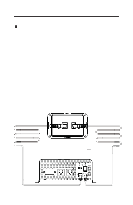
Connecting to the PGH Inverter series
The RMS-PGH will operate when the PGH Inverter is in the ON
or REM position. Only in the REM position, will the RMS-PGH
be able to manually turn the inverter ON/OFF in addition to
monitoring the inverter.
Changing the frequency (50/60Hz) or the power mode
(Normal/Eco) will need to be done physically on the inverter.
The inverter then needs to be rebooted for the changes to take
effect on the monitoring screen.
In order to read the parameters of the inverter correctly,
1. The switch must be in the ON or REM position and the COMM
port correctly connected to the RJ45 cable.
2. The REMOTE port is correctly connected to the RJ12
communication cable
RJ45 Communication Port
RJ12 Communication Port
AC OUTPUT AC OUTPUT
L N G
ON
OFF
REM.
REMOTE
ECO
GF
COMM.
50Hz
60Hz Nor.
15
The RMS-PGH is ONLY compatible with PGH Inverter Series.
NOTE
NOTE
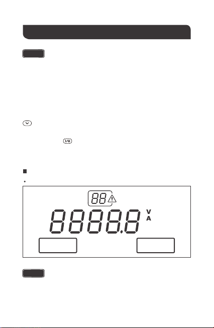
Operation
LCD Information
Overview
The following key is used to navigate through the screen
parameters
The communication cables need to be connected correctly in
order to read the parameters of the inverter correctly.
Changing the frequency or the power mode (Normal/Eco
mode) will need to be done on the inverter and then the
inverter rebooted for the changes to take effect on the
monitoring screen
The following key allows you to switch between input and
output parameters
INPUT
NOR
Hz
W
OUTPUT
ECO
16
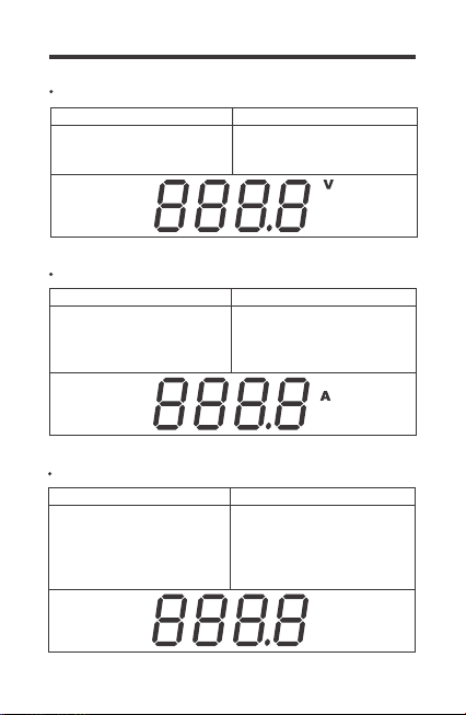
The voltage indicates the DC
Input voltage of the battery
bank. Volts will be in DC
The voltage indicates the AC
Load Voltage.
Volts will be AC
Voltage (V)
Input Output
Current (A)
The real-time current flowing
from the inverter to the AC
appliances. Current will be
AC amps
Input Output
W
Watts (W)
The real-time watts flowing
from the inverter to AC
Appliances. Watts is
calculated based on AC
Values
Input Output
-
-
17
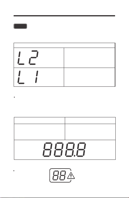
AC Watts < 50W
50W < AC Watts < 100W
Output
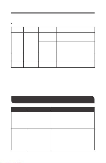
Error Code
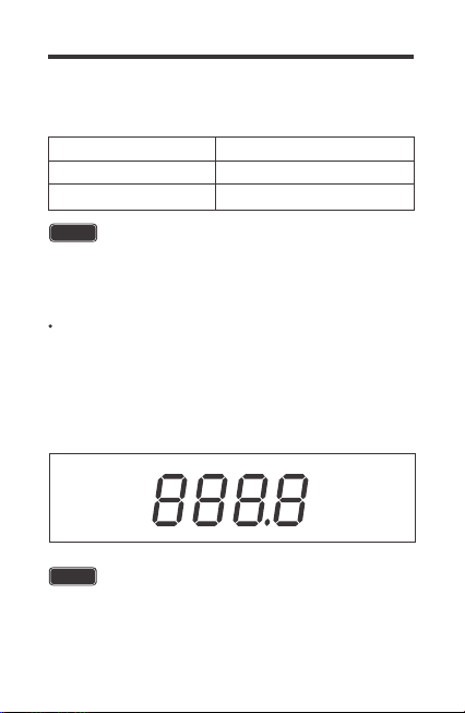
Hz
The monitoring screen will only be able to monitor the working
mode. To change the output frequency the DIP switch needs to
be physically selected on the unit BEFORE turning on the inverter.
Frequency (Hz)
-
Displays the frequency of the
inverter output to operate AC
appliance
Input Output
W
W
NOTE
The RMS-PGH will not calculate the watts below 100 watts.
Instead the following code will display depending on the watts
18
The error code indicates potentially abnormal conditions of the
inverter. During normal operation this will not display on the screen.
Hz
Battery Under-Voltage Warning
Battery Over-Voltage Warning
Error Code Parameter
01
02
The PGH inverter features a power saving mode (ECO) to
conserve battery power. The monitoring screen will only be able to
monitor the working mode. To operate in ECO or Normal working
mode, the DIP switch needs to be physically selected on the unit
BEFORE turning on the inverter. The normal (NOR) icon will be
on the left and the Eco Mode(ECO) icon on the right.
NOTE
Under ECO mode, the inverter senses the output for a load
greater than 50W. Loads under 50W will not be powered and
the inverter will stay idle.
Normal / ECO Mode
NOTE
The error code will flash, and the inverter will beep the alarm.
Upon the battery reaching the error state, the monitor screen
will shut down just like the inverter.
19
LED Indicators
The inverter is powered
on in normal mode
The inverter is powered in
ECO mode detecting a
load to power >50W
LED Parameter
ON
ELEC
Color
Green
Yellow
Behavior
Solid
Solid GFCI Trip
ERR Red Solid Fault
Slow Flash
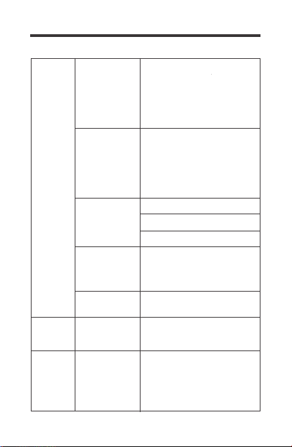
Troubleshooting
Input voltage
below 11V
Error
Code 01,
ERR LED
Lit
Error
Code 02,
ERR LED
Lit
Input voltage is
above 15V
Use a multimeter to check the
voltage of the battery bank.
Disconnect any loads if any and
make sure you're only using
12V battery bank systems.
Use a multimeter to check the
voltage of the battery bank.
Disconnect any loads and
charge the battery back up.
Indicator TroubleshootPotential Issue
20
Inverter
under-voltag
e protection
Inverter
over-voltag
e protection
GFCI
tripped
Use a higher wattage inverter
or use a lower powered device
Disconnect the inverter and turn
off the ON/OFF switch to reset
Disconnect appliances and turn
off the ON/OFF switch to reset
Inverter
overheats
Operating
equipment
draws too much
power
Yellow LED
Lit - Inverter
shut down
Incorrect
wiring
Make sure the RJ12 cable is
connected to the REMOTE port
and the RJ45 communication
cable is connected to the
COMM port.
Monitor
Screen
does not
turn on
Monitor
screen
shutdown
Inverter is
short circuited
Use a multimeter to check the
voltage of the battery bank to
make sure you're above 11V.
Disconnect loads if any and
make sure you're only using
12V battery bank systems.
Use a multimeter to check the
voltage of the battery bank to
make sure you're below 15V.
Disconnect loads if any and
make sure you're only using
12V battery bank systems.
Allow inverter to cool down
Check for adequate ventilation
Reduce the load on inverter
21
Technical Specifications
Electrical Specifications
Mechanical Specifications
Supply Voltage
Supply Current
Power Consumption
Operating Temperature Range
Voltage Accuracy
Current Accuracy
Communication Port
Display
RJ45, RJ12
Backlit LCD
5VDC
30mA
<1W
-4℉~113℉ / -20℃~45℃
±0.1V
±0.1A
Dimension
Weight
User Interface
2 key input,
1 main power switch
Mounting System
2.8*4.3*1.3 inch
70*110*31.8 mm
0.14 lbs / 62 g
Mounting Screw
Certification
FCC Part 15 Class B,
CE, RoHS
2.9*13mm
RJ45 Wire Length
16.4 Ft / 5m
RJ12 Wire Length
16.4 Ft / 5m
Model RMS-PGH
Wall Mount

22
This device complies with Part 15 of the FCC Rules. Operation
is subject to the following two conditions: (1) this device may not
cause harmful interference, and (2) this device must withstand
any interference received, including interference that may cause
undesired operation.
This equipment has been tested and found to comply with the
limits for a Class B digital device, pursuant to part 15 of the
FCC Rules. These limits are designed to provide reasonable
protection against harmful interference in a residential
installation. This equipment generates, uses and can radiate
radio frequency energy and, if not installed and used in
accordance with the instructions, may cause harmful
interference to radio communications. However, there is no
guarantee that interference will not occur in a particular
installation. If this equipment does cause harmful interference
to radio or television reception, which can be determined by
turning the equipment off and on, the user is encouraged to try
to correct the interference by one or more of the following
measures:
Reorient or relocate the receiving antenna.
Increase the separation between the equipment and receiver.
Connect the equipment into an outlet on a circuit different
from that to which the receiver is connected.
Consult the dealer or an experienced radio/TV technician for
help.
FCC Compliance:
NOTE

Renogy reserves the right to change
the contents of this manual without notice.
RENOGY.COM
US
2775 E Philadelphia St, Ontario, CA 91761, USA
909-287-7111
www.renogy.com
support@renogy.com
https://www.renogy.cn
support@renogy.cn
CN
400-6636-695
苏州高新区科技城培源路1号5号楼-4
CA
https://ca.renogy.com
supportca@renogy.com
https://au.renogy.com
supportau@renogy.com
AU
JP
https://www.renogy.jp
supportjp@renogy.com
https://uk.renogy.com
supportuk@renogy.com
UK
https://de.renogy.com
supportde@renogy.com
DE