Version 1.0
FOR DC-DC BATTERY CHARGER SERIES
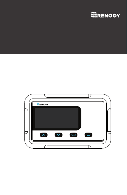
MONITORING
SCREEN
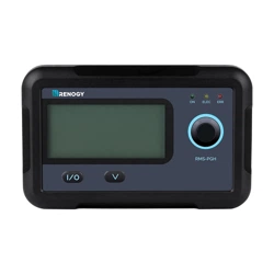
RMS-DCDC
01
General Safety Information
This manual contains important installation and operation
instructions for the monitoring screen. Please observe these
instructions and keep them located near the monitoring screen for
further reference. The following symbols are used throughout the
manual to indicate potentially dangerous conditions or important
safety information.
Make sure all connections going into and from the DC-DC are
tight. There may be sparks when making connections,
therefore, make sure there are not flammable materials or
gases near installation.
DO NOT expose it to direct sunlight, rain, snow, moisture, or
liquids of any type.
Important Safety Instructions
Please save these instructions.
Indicates a potentially dangerous condition. Use
extreme caution when performing this task.
Indicates a critical procedure for the safe and proper
installation and operation of the monitoring screen.
Indicates a procedure or function that is important
to the safe and proper installation and operation of
the monitoring screen.
NOTE
CAUTION
WARNING
DO NOT puncture, drop, crush, burn, penetrate, or strike
the monitoring screen.
DO NOT open, dismantle, or modify the monitoring screen.
Installation Information
DO NOT attempt connecting the monitoring screen to other
DC-DC or systems.
The DC-DC are suitable for 12V Battery Banks ONLY.
Always make sure DC-DC is in OFF position and disconnect all
sources when working on any circuit associated with the DC-DC.

02
Table of Contents
Important Safety Instructions
01
General Information
04
Product Overview
05
Identification of Parts
05
Dimensions
06
Voltage Interface
18
Operation
14
Troubleshooting
31
Technical Specifications
35
LCD Icons
15
LCD Menu Overview
17
Kilowatt Interface
18
Current Interface
18
Temperature Interface
18
Working Mode
19
Parameter Setting
23
Set the Battery Type
23
Clear KWh to 0
28
Set Current Limiting
28
Change from Celsius to Fahrenheit
30
Installation
08

03
General Information
Plug and Play
Accurate Readings
The RMS-DCDC is a high precision meter designed for DC-DC
MPPT Series on board battery chargers. Featuring a backlit display
and flush-mountable, it is engineered for an aesthetically clean and
professional look inside vehicle cabins. Utilize the 4-key input to
navigate through the backlit LCD for system information, configure
charging parameters, as well as identify any error codes. The
RMS-DCDC is the perfect companion offering operator feedback
your 2-battery system and keeping up to date with important system
information.
Dual Battery Monitoring
Stay informed on the charging status of your house and auxiliary
battery and monitor overall system health.
Adjustable Parameters
Program your charger settings, volts, and amps directly through
the monitoring screen.
Precise tracking and monitoring ensure latest real-time system
information.
Simply connect an RJ45 directly to your DC-DC and let the
screen take care of the rest.
Key Features
04
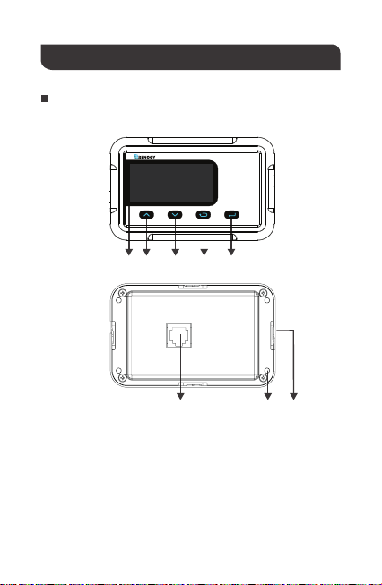
Product Overview
LCD Screen
Page Up
Page Down
Previous Page
Enter
Front Cover Plate
Mounting Holes
RJ45 Communication Port
①
②
③
④
⑤
⑥
⑦
⑧
Identification of Parts
②① ③ ④ ⑤
RMS-DCDC
⑥⑦⑧
05
Dimensions
1.24in
0.8in
31.5mm
19.9mm
Dimensions have a tolerance of ±0.5mm
RMS-DCDC
110.0mm
4.3in
87.5mm
3.4in
2.8in
70.0mm
NOTE
06
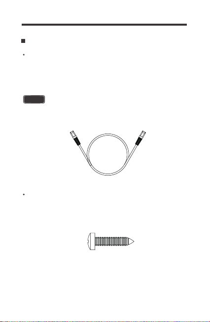
Additional Components
RJ45 Communication Cable
You may use ethernet cables CAT5 or higher.
The RJ45 Communication Cable (5m/16.4ft) is used to connect the
monitoring screen to t power supply and data transmission.
Self-tapping Screws (4)
The Self-tapping Screws (M2.9x13) are used fix the monitoring
screen on the mounting surface.
NOTE

07
NOTE
Before installation, check to make sure the power is working
properly. Resolve any issues before installation of monitoring
screen and cable.
The following are recommendations for installation. There will be
multiple mounting methods depending on user’s applications.
Clearance of at least 2 inches (50 mm) behind the unit is recommend-
ed to allow for the bending radius of the RJ45 Communication Cable
that connects to the monitoring screen.
The RMS-DCDC requires a flush mount installation. The RMS-DC-
DC’s faceplate will be flush with the mounting surface and the
body of the meter.
Before the installation of the monitoring screen, it is recommended
to have the following tools available:
CAUTION
Installation
Before drilling, make sure there are no electrical component or
other obstacles that may interfere with installation on the other
side of the mounting surface.
WARNING
Preparation
Choosing an Installation Location
Pencil
Drill
Jigsaw
Phillips screwdriver
08
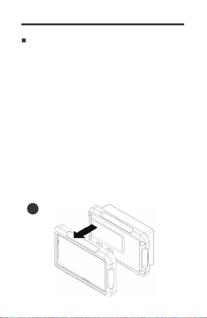
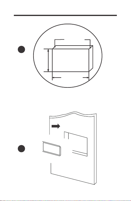
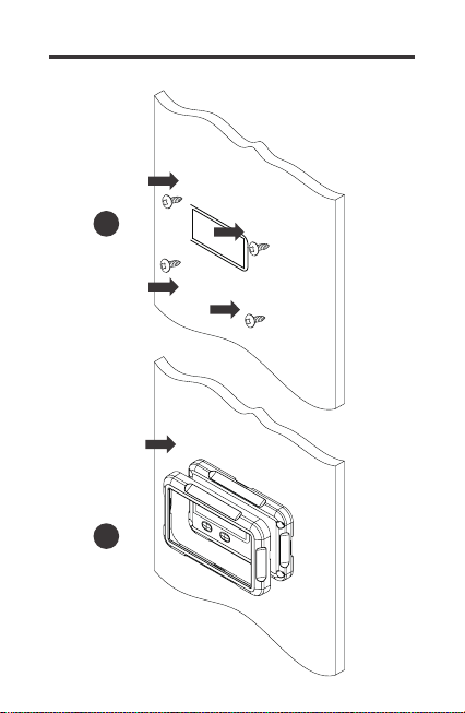
2. Use the monitoring screen as a template to mark the screw holes
and trace the cut-out area on the mounting surface with a pencil.
1. Remove the snap-fit Front Cover Plate from the monitoring
screen.
3. Cut out a rectangle area for the monitoring screen on the
mounting surface with a jigsaw. You may also use the cut out
dimension specified after Step 2.
5. Put the monitoring screen into the cut-out area and align the
mounting holes on the monitoring screen with the pre-drilled screw
holes.
6. Fix the monitoring screen on the mounting surface with the
included four self-tapping screws.
7. Re-attach the snap-fit Front Cover Plate to the monitoring
screen.
4. Pre-drill four screw holes on the mounting surface with a drill.
Mounting the Monitoring Screen
1
09
2
3
10
4
Cutout Dimensions (L x H x W):
87.5 x 58.0 x 19.9mm
(3.44 x 2.28 x 0.78in)
87.5mm
3.44in
58.0mm
2.28in
19.9mm
0.78in
5
11
7
6
12
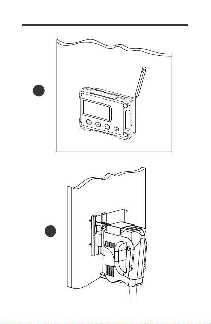
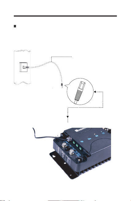
Connecting to the DCDC
Utilize the included RJ45 communication cable to connect between
the DC-DC MPPT RS485 Port and the back of the RMS-DCDC.
RJ45 Communication cable
13
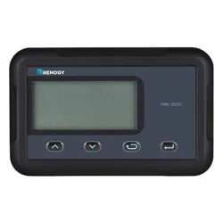
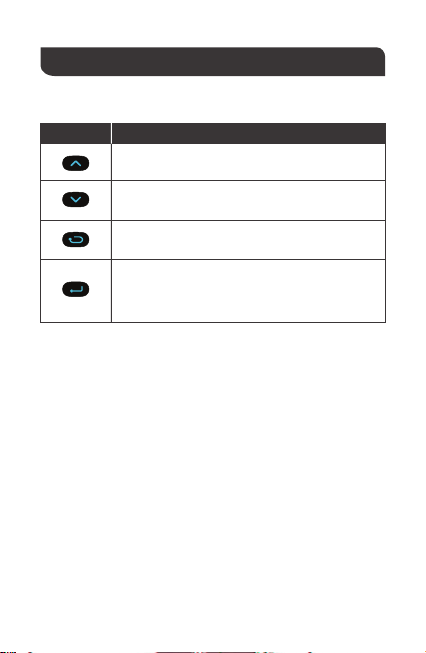
Key Meaning
Page Up
Page Down
Operation
Use the following keys to navigate through the monitoring screen
Previous Page
Exit Parameter Setting Mode
Enter—Tap to Enter
Parameter Setting Key—Hold for approximately
2~3 seconds to enter parameter setting mode
14
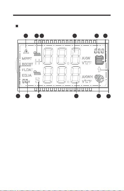
LCD Icons
Key Features
2 1 12 11 10
876543
9
1. System Voltage
The 12V system voltage will be illuminated while the RMS-DC-
DC is powered on or during operation.
2. State of charge
Whether charging with PV, Alternator, or PV + Alternator, the
charge state will reflect either MPPT, BOOST, FLOAT. Only
batteries with an equalization charge will see EQUALIZE.In
addition, Lithium batteries will display MPPT and Boost only.
3. System Error
Illuminates when there is a fault or error. It will be followed by an
error code identifying the system error. The icon must be cleared
by fixing the error code condition by troubleshooting your system.
15
4. Solar Charging Icon
Indicates solar is charging the house battery. Solar will take
priority over alternator charging.
Error Code Description
Normal
5. House Battery Icon
When “H” is shown with parameters, it refers to the house battery
parameters.
6. Parameter Units
Total Charging Amps (A), Instant Kilowatt (KWH), Voltage (V), and
Temperature (◦C or ◦F).
7. Error Codes
System error will display a relevant error code from E0~E03、
E05~E10、E12、E13. By default, E0 means no fault and will
display for 3-seconds before disappearing. The following error
codes may come up and will need some troubleshooting to clear
them. Refer to the Troubleshooting section.
E0
House Battery Over-discharged
E1
House Battery Over-voltage
E2
House Battery Low Voltage Warning
E3
House Battery Low Temperature ProtectionE5
House Battery High Temperature Protection
E7
Alternator Over-voltage Warning
E8
Alternator Overcurrent
E9
PV Input Over-voltage
E10
Starting Battery Polarity Reversed
E12
Solar Panel Polarity Reversed
E13
E6 Controller High Temperature Warning

16
LCD Menu Overview
8. House Battery SOC Icon
Indicates the estimated state of charge of the house battery. State
of charge is voltage based and will be split into 4 bars each
representing 25% increments for a total of 100%. Factors such as
temperature, charge, and discharge can affect the state of charge.
To get the most accurate SOC readings, the battery needs to rest
in the open circuit state for at least 30-45min.
9. Alternator Charging Arrow
Shows that alternator is charging the starter battery or house battery
circuits.
10. Alternator Icon
Displays when connected to a starter battery successfully. Charging
will be indicative by the charging arrow mentioned above.
11. Battery Parameters
Battery Amps (A), Historical Kilowatt-hour Generation (KWH),
Voltage (V), and Temperature (◦C or ◦F) relevant to the starter battery.
12. Starter Battery Icon
When “S” is shown with parameters, it refers to the starter battery
parameters.
Navigate through the RMS-DCDC screens by pressing the page
up or page down keys.
17
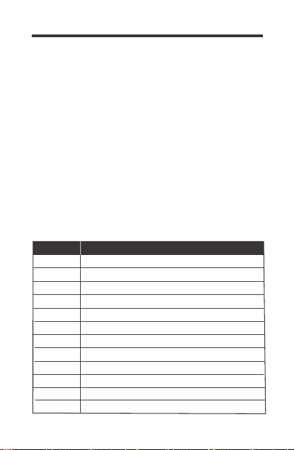
Voltage Interface
The top line displays the house
battery (DC Output) voltage as
well as a graphical display of
the battery using voltage-based
SOC. Each bar represents 25%
for a total of 100%. The bottom
line shows the starter battery
(DC Input) voltage.
Kilowatt Interface
The top line displays instantaneous
watts as a factor of kilowatts (KW).
This will be the charging voltage (V)
multiplied by the charging current (A)
to display Kilowatts. 1 KW = 1000W.
The bottom line displays historical
kilowatt hour generation information
(KWH) and will accumulate the data.
Current Interface
Temperature Interface
The top line displays overall charging
current to the house battery (Only
Solar, Only Alternator, or Solar +
Alternator). The bottom line displays
the input alternator current.
Temperature will be in Celsius (◦C)
by default. The top line shows the
house battery temperature relative
to the DC-DC MPPT. When connected
to the Temperature Sensor (Model:
RTSCC), then it will show the relevant
sensor temperature. The bottom line
displays the internal temperature
of the DC-DC MPPT
18
Once the RMS-DCDC is on, it will display different pages depending
on the sources connected. PV Charing Mode will take priority when
charging the house or starter batteries. House battery information will
appear on the top line and starter battery information in the bottom line.
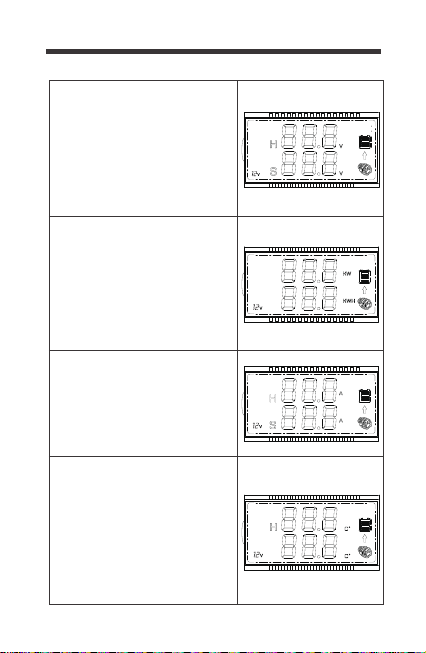
Working Mode
Only PV Charging—Starter Battery & House Battery
Connected
1.PV charging requires a minimum
of 15V for 10s to start charging. PV
will prioritize charge to the house
battery bank and charge until the
lead-acid battery reaches the Float
Voltage. If the house battery is
Lithium, then it will reach the Boost
Voltage and derate amps complete-
ly to indicate fully charged since
they do not have a Float Voltage.
2.Next, PV charging will maintain
the house battery and trickle
charge the starter battery at 13.8V.
The Generator charging arrow will
appear during this time.
*Note: The maximum charging
amps for the starter battery will
be 50% of the Amp Rating.
3.After charging the starter battery
for 1 minute, it will disconnect for
30s and check the starting battery
voltage. If the starter battery drops
below 12.7V, charge will continue again
and stop when the actual starter
battery voltage is higher than 13.2V

19
4.When and if PV charges both the
house battery and starter battery at
the same time, there will be a solar
icon above the H and S.
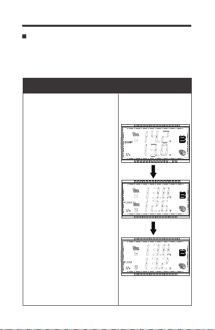
Only ALT Charging—Starter Battery & House Battery
Connected
1.ALT charging will follow this chart, depending on your
alternator type.
Alternator Type
Cut-in Cut-off
Starting Battery Voltage
Smart Alternator
Traditional Alternator
>13.2V,
for 15 seconds
<12.7V
>12.0V,
for 15 seconds
<11.5V
2. ALT will prioritize charge to the
starter battery bank and charge until
the starter battery reaches above
the Cut-in Voltage.
3.Next, ALT will charge the house
battery until the lead-acid battery
reaches the Float Voltage. If the
house battery is Lithium, ALT will
need to reach the Boost Voltage and
derate amps completely to indicate
fully charged.
20
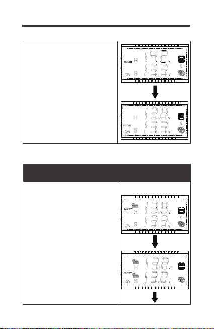
PV + ALT Charging—Starter Battery & House Battery
Connected
1.PV charging will be maximized
before supplementing any power
with ALT charging. If PV charging
alone is enough to charge the house
battery, then the ALT circuit will not
charge the house battery.
2.If PV charging is not enough to
keep a constant voltage, then the
ALT circuit will cut in to charge the
house battery. In this fashion, dual
charging is limited to 50% between
PV and ALT for a total up to the
rated charging amps.
4.When no current is detected going
to the House Battery, the ALT charging
arrow will disappear.

21
1. Use the Page Up/Down keys to show the Voltage Interface.
Hold down Parameter Setting Key for approximately 2-3seconds
and the top line will begin flashing the battery type.
You can change the battery type to confirm the preselected battery
profiles for Gel, Flooded, Sealed, Lithium, or a User Setting. Lithium
and User settings require extra steps. The battery Charging Chart
can be found in the Technical Specifications.
Parameter Setting
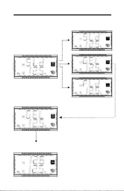
Set the Battery Type
Setting Gel, Flooded, or Sealed
2. Use the Page Up/Down to highlight Gel, flooded (Fld), or
Sealed (Sld).
3. To confirm, hold down the Parameter Setting Key for approximate-
ly 2-3seconds. The screen will clear and revert to the House
Battery Voltage.
3.Charging of both starter and
house battery at the same time will
be indicative of solar icon over the
S and the ALT charging arrow.
22
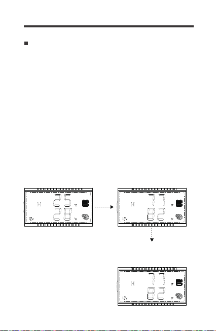
1.Hold the Param. Setting
key for 2-3s until flashing
3.Confirm battery by holding
Param. Setting key for 2-3s
Voltage Interface
2.Use Up/Down keys to
highlight battery
4.Confirm setting by holding
Param. Setting key for 2-3s

23
3. Tap the Parameter Setting Key to select the Boost charge voltage.
Use the Page Up/Down keys to select your desired voltage.
4. To confirm, hold down the Parameter Setting Key for approximately
2-3seconds. The screen will clear and revert to the House Battery
Voltage.
Setting Lithium
1. Use the Page Up/Down key to show the Voltage Interface.
Hold down Parameter Setting Key for approximately 2-3seconds
and the top line will begin flashing the battery type.
2. Use the Page Up/Down to highlight Li (Lithium).
1.Hold Param. Setting
key for 2-3s until flashing
3.Use Up/Down keys to
highlight Boost Voltage
4.Confirm setting by
holding Param. Setting key
for 2-3s
2.Use Up/Down keys to
highlight Lithium “Li”, then
Tap Param. Setting key

24
Modifying parameters in User Mode or Lithium must conform to
the following rules:
1. Equalization Voltage ≥ Boost Voltage ≥ Float Voltage
2. Overvoltage Disconnect > Overvoltage Disconnect Recover
Setting User
1. Use the Page Up/Down keys to show the Voltage Interface.
Hold down Parameter Setting Key for approximately 2-3seconds
and the top line will begin flashing the battery type.
3. Tap the Parameter Setting Key to select the Boost charge
voltage. Use the Page Up/Down arrows to highlight your desired
voltage.
4. Tap the Parameter Setting Key again to select Float voltage.
Use the Page Up/Down keys to highlight your desired voltage.
5. Tap the Parameter Setting Key to select the Equalization voltage.
Use the Page Up/Down keys to highlight your desired voltage.
6. To confirm, hold down the Parameter Setting Key for approximate-
ly 2-3seconds. The screen will clear and revert to the House
Battery Voltage
2. Use the Page Up/Down to highlight User (USE).
NOTE
25
1.Hold the Param. Setting
key for 2-3s until flashing
2.Use Up/Down keys to
highlight “USE” then Tap
Param. Setting key
3.Use Up/Down keys to
highlight boost voltage, then
Tap Param Setting key
4.Use Up/Down keys to
highlight float voltage, then
Tap Param Setting key
5.Use Up/Down keys to highlight
equalization voltage, then
Tap Param Setting key
6.Confirm setting by holding
Param. Setting key for 2-3s
26
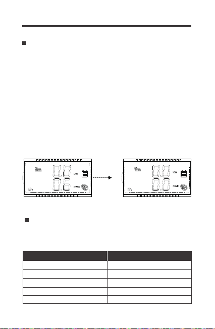
1. Use the Page Up/Down keys to show the Kilowatts Interface.
Hold down Parameter Setting Key for approximately 2-3seconds
and the bottom line will begin flashing
The kilowatt hour generation will automatically store historical
information. To clear the values to 0:
Clear KWh to 0
2. Press the Page Up Key to clear the generated kilowatt generation
3. Press the Previous Page Key to revert to the kilowatts interface
Alter the rated charge current for your DCDC MPPT by setting
current limiting. Current limiting can be adjusted in increments of
10A for the respective models:
Set Current Limiting
30A
20A
10A
50A
40A
30A
20A
10A
DCC30S (Model: RBC30D1S) DCC50S (Model: RBC50D1S)
1.Hold down Param. Setting
Key for 2-3s until flashing
2.Press UP to clear KWH
Kilowatts Interface
27
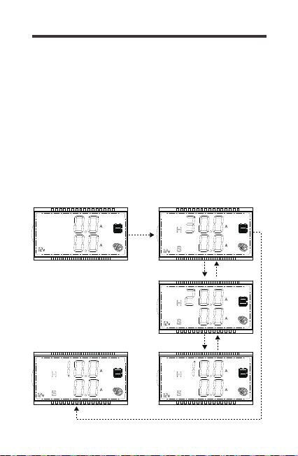
1. Use the Page Up/Down keys to show the Current Interface.
Hold down Parameter Setting Key for approximately 2-3seconds
and the top line will begin flashing rated current rating
2. Use the Page Down to highlight your desired current limit rating
To get started:
1.Hold down the Param.Set-
ting key until flashing
2.Use the Page Down to
highlight your desired
current limit rating
3.To confirm, hold down
the Para.Setting Key for
2-3seconds.
Current Interface
3.To confiem,hold down the Parameter Setting Key for approximate-
ly 2-3seconds. The screen will clear and rever to the Current Interface
28
1. Use the Page Up/Down keys to show the Temperature Interface.
Hold down Parameter Setting Key for approximately 2-3seconds
and the top and bottom lines will flash.
The default temperature is Celsius. If the RMS-DCDC is restarted,
then it will refer to the default setting. Change from Celsius to
Fahrenheit or vice versa:
Change from Celsius to Fahrenheit
2. Tap the Parameter Setting Key to change units from Celsius
to Fahrenheit.
3. To confirm, hold down the Parameter Setting Key for approximate-
ly 2-3seconds. The screen will clear and revert to your selected
temperature units.
1.Hold down Param
Setting Key for 2-3s
until flashing
2.Tap the Param Setting
key to change ℃-℉ or
vice versa
3.Confirm by holding
down Param. Setting key
for 2-3s

29
Troubleshooting
The RMS-DCDC provides you with a visual for what is
occurring in the system. When the RMS-DCDC is not operating
correctly, then you will need a multi-meter to validate some of
the troubleshooting steps.
RMS-DCDC
does not
turn on
Make sure you are using the provided cable
or that it is a CAT5 or higher if using your own
2.
1.
Make sure the DC-DC MPPT is also powered
on prior to connecting the cable.
3.
Contact Support.
4.
Firmly press the ethernet jack onto the back
port on the RMS-DCDC until you hear aclicking
sound. Do the same when connecting it to the
RS485 port on the DC-DC MPPT.
House
Battery
Over-
discharged
E1
Double check your battery type setting to
determine whether it is correctly set.
2.
1.
Use a multi-meter to determine and validate
the high charging voltage.
Disconnect any extraneous chargers.
4.
3.
Contact support if over-charge continues.
House
Battery
Over-voltage
E2
Ensure you have a charging source through
alternator or solar as the battery needs to
be charged.
2.
1.
Disconnect any loads from the house battery
and allow it to recharge.
3.
Use a multi-meter to measure the battery and
then the battery terminals to determine consisten-
cy, any inconsistency could be a break in the
line.
Error Codes
Troubleshooting
Problem-Solution

30
The warning is letting you know that you’re
using more than your battery can supply.
2.
1.
It is recommended to limit your load use to not
run the battery to empty
It is also recommended to connect a charging source,
solar or alternator, to slow down the battery draining.
3.
House
Battery Low
Voltage
Warning
E3
The temperature sensor on the DC-DC MPPT
or on the remote sensor (Model: RTSCC) is
detecting low temperature at the house battery
and has ceased charging.
2.
1.
Lithium battery may have reached a freezing
point and cut off charge. Relocate the battery if
conditions are freezing.
3.
The condition will recover upon temperature getting
warmer or if relocating the DC
-DC MPPT in a better
ambient temperature to continue normal work mode.
4.
Ensure you’re not using the RTSCC on lithium batteries.
House
Battery Low
Temperature
Protection
E5
The temperature sensor on the DC-DC MPPT or
on the remote sensor (Model: RTSCC) is detecting
high temperature and has cease charging.
2.
1.
The condition will recover upon temperature getting
cooler or if relocating the DC
-DC MPPT in a better
ambient temperature to continue normal work
mode.
3.
Check for loose connections and ensure no
heating sources around the battery.
House
Battery High
Temperature
E7
Controller
High
Temperature
E6
1.The temperature sensor on the DC-DC MPPT or
on the remote sensor (Model: RTSCC) is detecting
high temperature and has cease charging.
2.Limit the charge current to cool down the
work mode of the DC
-DC MPPT.
3.The condition will recover upon temperature
getting cooler or if relocating the DC
-DC MPPT
in a better ambient temperature location to
continue normal work mode.

31
1. Disconnect the starter battery from the circuit
2. Double check the alternator voltage does not
exceed 16.5V.
Alternator
Over-voltage
Protection
E8
The panel is producing voltage higher than the
25V operating voltage of the DC-DC MPPT.
2.
1.
Contact support if overvoltage condition continues
and the operating voltage is under 24.5V
3.
Double check your connections and make sure
you’re not exceeding 25.5Volts open. Use a
multimeter to measure the panel leads and
confirm not over voltage.
PV Input
Over-voltage
E10
1. Disconnect the starter battery from the circuit
2.
Check on the alternator charging rating to
ensure not over the 30A|50A limit.
Alternator
Overcurrent
E9
Your battery poles are reversed.
2.
1.
Fix the connection to continue normal operation.
4.
Assuming correct polarity from the Multimeter,
negative readings on the multi-meter indicate
reverse polarity.
3.
Fix the connection to resume normal working
mode. Use a multi-meter to measure the correct
polarity before connecting to the DC-DC MPPT
and ensure proper connection.
Starting
Battery
Polarity
Reversed
E12
Solar Panel
Polarity
Reversed
E13
Your solar panel poles are reversed.
1.
2. Fix the connection to resume normal working
mode.Use a multi-meter to measure the correct
polarity before connecting to the DC-DC MPPT
and ensure proper connection.
Fix the connection to continue normal operation
4.
Assuming correct polarity from the Multimeter,
negative readings on the multi-meter indicate
reverse polarity.
3.
Technical Specifications
Supply Voltage
Supply Current
Power Consumption
Operating Temperature Range
Voltage Accuracy
Current Accuracy
5VDC
30mA
<1W
-4℉~113℉ / -20℃~45℃
±0.1V
±0.1A
Electrical Specifications
Mechanical Specifications
Mounting Screw
Certifications
Dimension
Communication Port
Display
User Interface
Mounting System
Weight
M2.9x13
FCC Class B Part 15
2.8 x 4.3 x 1.24 inch
70 x 110 x 31.5 mm
RJ45 (RS485 Protocol)
Backlit LCD
2key input, 1main power switch
Wall Mount
0.14 lbs / 62 g
32

33
120min 120min 120min
0~120
min
Boost
Duration
--- ---
28
days
0-30
days
Equalization
Interval
--- --- 120min
0~120
min
Over-
voltage
Recover
Variable
until Full
---
---
120min
28
days
0-120
min
14.6V 14.2V 14.6V
13.2V-
15.5V
Boost
Charge
Voltage
13.8V 13.8V 13.8V
13.2V-
15.5V
Float
Charge
Voltage
--- --- 14.8V
13.2V-
15.5V
Equalization
Voltage
13.2V 13.2V 13.2V N/A
Boost
Return
Voltage
12V 12V 12V N/A
Under
Voltage
Warning
12.2V 12.2V 12.2V N/A
Under
Voltage
Recover
11.1V 11.1V 11.1V N/A
Over-
discharge
Warning
12.6V 12.6V 12.6V
14.4V
(adjustable)
---
---
13.2V
12.1V
12.2V
11.1V
12.6V
Battery Charging Chart
Battery
Type
Parameters
SLD/
AGM
16V 16V 16V
N/A
GEL
FLD
Custom
Range
(USER/LI)
Over-
voltage
Warning
15.5V 15.5V 15.5V N/A
Charging
Limit
Voltage
16V
LI
(LFP)
15.5V
16V
USER
(Default)
15.5V
15V 15V 15V N/A
Over-
voltage
Recover
15V 15V
14.6V
(adjustable)
13.8V
(adjustable)
14.6V
(adjustable)
13.2V
12V
12.2V
11.1V
12.6V N/A
Over-
discharge
Recover

34
• Reorient or relocate the receiving antenna.
• Increase the separation between the equipment and receiver.
• Connect the equipment into an outlet on a circuit different from
that to which the receiver is connected.
• Consult the dealer or an experienced radio/TV technician for help.
This device complies with Part 15 of the FCC Rules.
Operation is subject to the following two conditions:
(1) this device may not cause harmful interference.
(2) this device must accept any interference received, including
interference that may cause undesired operation.
NOTE
User Mode is an extra feature accessed via App Development
Only or Monitoring Screen. However, Boost Duration, Equaliza-
tion Interval, and Equalization Duration can only be programmed
through App Development.
The battery charging parameters assume conditions to be 77℉ /
25℃ in 12V systems.
NOTE
This equipment has been tested and found to comply with the
limits for a class B digital device, pursuant to part 15 of the FCC
Rules. These limits are designed to provide reasonable protection
against harmful interference in a residential installation. This equipment
generates, uses and can radiate radio frequency energy and if not
installed and used in accordance with the instructions,may cause
harmful interference to radio communications. However, there is
no guarantee that interference will not occur in a particular
installation. If this equipment does cause harmful interference
to radio or television reception, which can be determined by turning
the equipment off and on, the user is encouraged to try to correct
the interference by one or more of the following measures:
Renogy reserves the right to change
the contents of this manual without notice.
RENOGY.COM
US
2775 E Philadelphia St, Ontario, CA 91761, USA
909-287-7111
www.renogy.com
support@renogy.com
https://www.renogy.cn
support@renogy.cn
CN
400-6636-695
苏州高新区科技城培源路1号5号楼-4
CA
https://ca.renogy.com
supportca@renogy.com
https://au.renogy.com
supportau@renogy.com
AU
JP
https://www.renogy.jp
supportjp@renogy.com
https://uk.renogy.com
supportuk@renogy.com
UK
https://de.renogy.com
supportde@renogy.com
DE