Version 1.1
FOR ROVER ELITE SERIES
MONITORING
SCREEN
01
Disclaimer
The manufacturer accepts no liability for any damage caused by:
Must be properly ventilated to ensure no build-up of
explosive gases prior to installation.
Force majeure including fire, typhoon, flood, earthquake, war,
and terrorism.
Intentional or accidental misuse, abuse, neglect or improper
maintenance, and use under abnormal conditions.
Improper installation,
improper operation, and malfunction
of
a peripheral device.
Contamination with hazardous substances, diseases,
vermin, or radiation.
Alterations to the product without express written consent
from the manufacturer.
Important Safety Instructions
Please save these instructions.
This manual contains important installation and operation
instructions for the monitoring screen. Please observe these
instructions and keep them located near the monitoring
screen for further reference. The following symbols are used
throughout the manual to indicate potentially dangerous
conditions or important safety information.
Indicates a potentially dangerous condition. Use
extreme caution when performing this task.
Indicates a critical procedure for the safe and proper
installation and operation of the monitoring screen.
Indicates a procedure or function that is important
to the safe and proper installation and operation
of the monitoring screen.
NOTE
CAUTION
WARNING

02
General Safety Information
Charge Controller Safety
Read all of the instructions and cautions in the manual before
beginning the installation.
There are no serviceable parts for this controller. Do NOT
disassemble or attempt to repair the controller.
Do
NOT
allow water to enter the controller.
Make sure all connections going into and from the controller
are tight.
NEVER connect the solar panel array to the controller
without a battery. Battery must be connected first.
Ensure input voltage does not exceed 100 VDC to prevent
permanent damage. Use the Open Circuit Voltage (Voc) to
make sure the voltage does not exceed this value when
connecting panels together.
CAUTION
The monitoring screen is designed for indoor/compartment
installation. DO NOT expose it to direct sunlight, rain, snow,
moisture, or liquids of any type.
DO NOT puncture, drop, crush, burn, penetrate, or strike the
monitoring screen.
The monitoring Screen is only compatible with Renogy Elite
Series charge controllers. DO NOT attempt connecting the
monitoring screen to other charge controllers or systems.
DO NOT open, dismantle, or modify the monitoring screen.

03
Table of Contents
Important Safety Instructions
01
General Information
04
Product Overview
05
Identification of Parts
05
Dimensions
06
LCD Indicators
14
Operation
12
LCD interface
12
Navigating through Screens
13
Programming Battery Type
15
Selecting Lithium
17
Lithium Battery Activation
18
Troubleshooting
19
Technical Specifications
24
Installation
07

04
General Information
Comprehensive Protection
Easy Operation
The RMS-RVRE is a high precision meter designed for Rover
Elite charge controllers. Featuring a backlit display and
flush-mountable, it is engineered for an aesthetically clean and
professional look on RVs or camper walls. Utilize the 4-key
input to easily navigate through your system information or
modify quick parameters as well as identify any error codes.
The RMS-RVRE is the perfect monitor companion to optimize
any solar system!
Plug and Play
Simply connect the monitoring screen to the charge
controller using an RJ45 communication cable for real-time
monitoring.
Accurate Readings
Obtains charge controller status directly from the Rover Elite
for precise tracking and monitoring.
Shows detailed system information at the push of a button
without the need of system configuration and calibration
.
Displays straightforward warning codes for quick
recognition of potential abnormal conditions and improper
operation.
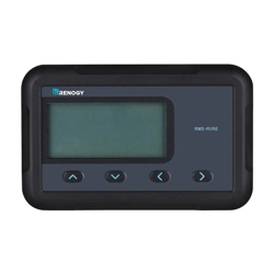
Key Features
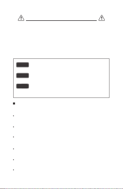
Product Overview
LCD Screen
Page Forward Button
Page Backward Button
Previous Page Button
Parameter Setting Button
Front Cover Plate
Mounting Holes Locations
RJ45 Communication Port
①
②
②
③
③
④
④
⑤ ⑥
⑤
⑥
⑦
⑧
Identification of Parts
05
①
RMS-RVRE
⑦ ⑧
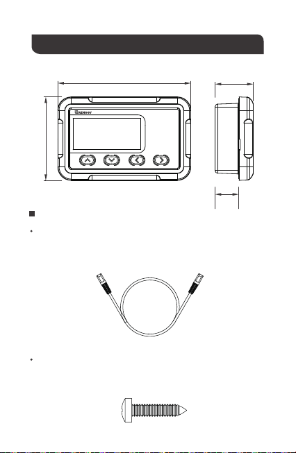
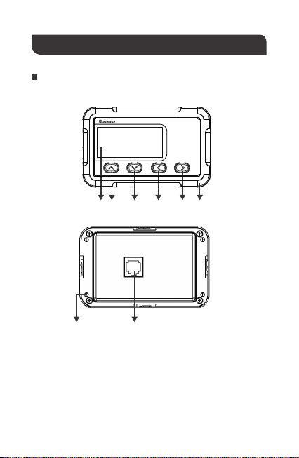
Dimensions
Additional Components
RJ45 Communication Cable
The RJ45 Communication Cable (5m/16.4ft) is used to connect the
monitoring screen to the charge controller for power supply and
data transmission.
Self-tapping Screws (4)
The Self-tapping Screws (M2.9x13) are used affix the monitoring
screen on the mounting surface.
06
110.3mm
4.34in 1.24in
0.8in
2.73in
69.3mm
31.5mm
19.9mm
RMS-RVRE

NOTE
07
Before installation, check to make sure the power is working
properly. Resolve any issues before installation of monitoring
screen and cable.
The following are recommendations for installation. There will be
multiple mounting methods depending on users’ applications.
Please choose a clean, dry, protected and easily accessible
indoor location to install the monitoring screen. It is
recommended to mount the monitoring screen at eye level for
easy access to the battery information and operation buttons.
The RJ45 Communication Port on the monitoring screen is
accessible from the back of the unit. Clearance of at least 2
inches (50 mm) behind the unit is recommended to allow for the
bending radius of the RJ45 Communication Cable that connects
to the monitoring screen.
The RMS-RVRE requires a flush mount installation. The
RMS-RVRE’s faceplate will be flush with the mounting surface
and the body of the meter.
Before the installation of the monitoring screen, it is recommended
to have the following tools available:
CAUTION
Installation
BEFORE drilling, make sure there are no electrical component
or other obstacles that may interfere with installation on the
other side of the mounting surface.
WARNING
Preparation
Choosing an Installation Location
Pencil Drill Jigsaw Phillips screwdriver
08
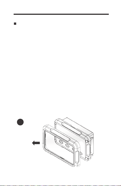
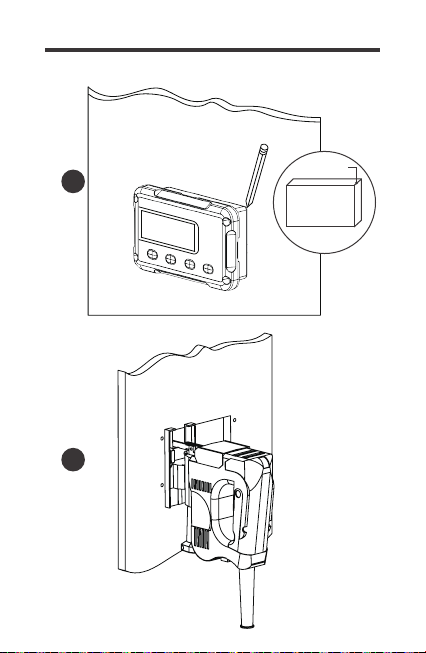
2. Use the monitoring screen as a template to mark the screw holes
and trace the cut-out area on the mounting surface with a pencil.
1. Remove the snap-fit Front Cover Plate from the monitoring
screen.
3. Cut out a rectangle area for the monitoring screen on the
mounting surface with a jigsaw. You may also use the cut out
dimension specified after Step 2.
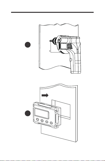
5. Put the monitoring screen into the cut-out area and align the
mounting holes on the monitoring screen with the pre-drilled
screw holes.
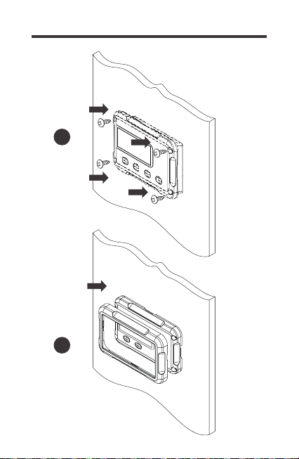
6. Fix the monitoring screen on the mounting surface with the
included four self-tapping screws.
7. Re-attach the snap-fit Front Cover Plate to the monitoring
screen.
4. Pre-drill four screw holes on the mounting surface with a drill.
Mounting the Monitoring Screen
1
09
2
3
Cutout Dimensions
(L x H x W):
86.7 x 58.02 x 19.8mm
(3.41 x 2.28 x 0.78 inch)
86.7mm
58.0mm
19.8mm
10
4
5
11
6
7
12
Operation
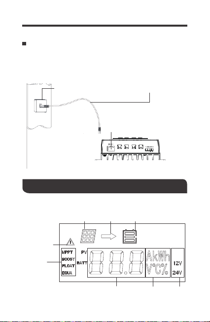
Connecting to the Charge Controller
Please connect the monitoring screen to the RS485 Port of the
Rover Elite using the included RJ45 Communication Cable.
RJ45
Communication Port
RJ45
Communication Cable
RJ45
Communication Port
solar panel
charging
battery
abnormality
charging
stage
parameter value unit system
voltage
LCD interface:
13
The RMS-RVRE is ONLY compatible with Rover
Elite Series charge controllers.
Once the monitoring screen is correctly
connected the following screen will display
with a delay of 6s before cycling through the
normal display.
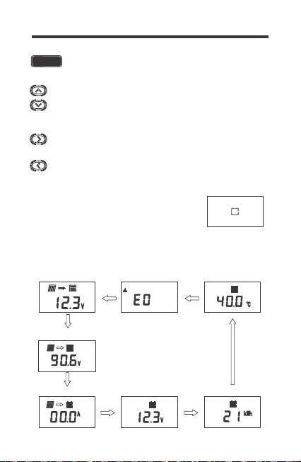
The following keys are used to navigate through system,
PV, and battery information as well as identifying any error
codes. Us the up and down keys to navigate through the
monitoring screens.
Enter parameter setting mode when highlighting the
appropriate screen and pressing down on the rightmost key.
Exit/Back when on parameter setting mode.
NOTE
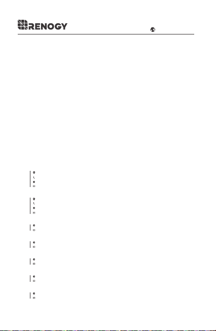
Navigating through Screens
Main Screen Error Code
Charging Current
BATT
12V
Accumulated AH
12V
Ambient Temperature
12V
Solar Panel Voltage
PV
12V
Battery Voltage
12V
BATT
BATT
MPPT
12V
14
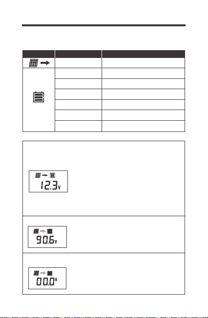
Here you will find your general system
information. You will see the charging
state of the controller (MPPT, BOOST,
FLOAT, EQUALIZATION), The battery
voltage measured, the system voltage
(12V or 24V) as well as the PV panel icon.
Please Note: The unit is charging when
you see the arrow, not necessarily when
you see the PV icon.
Solar Panel voltage is displayed indicated
by PV. The unit is charging if you see the
arrow going towards the battery bank icon.
Battery charging current is displayed.
Battery is charging if you see a value other
than 0 and the arrow going towards the
battery icon.
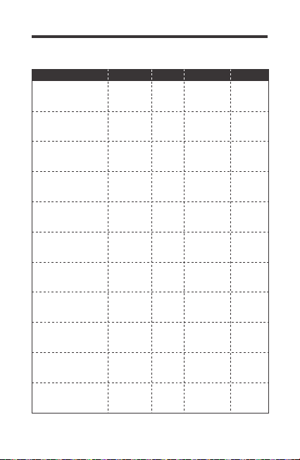
Icon or Value State Description
Steady on
3 Bars Flashing
3 Bars
2 Bars
1 Bar
No Bars
Solar Panels Charging Battery
Battery Voltage (16.1V+)
Battery Voltage (12.9V- 16.0V)
Battery Voltage (12.5-12.8V)
Battery Voltage (11.6-12.4V)
Battery Voltage (
11.5V and below)
Battery Voltage (
10.9V and below)No Bars Flashing
LCD Indicators
Main Screen
Charging Current
BATT
12V
Solar Panel Voltage
PV
12V
BATT
MPPT
12V
15
Programming Battery Type
Error Code
Accumulated AH
12V
Ambient Temperature
12V
Battery Voltage
12V
BATT
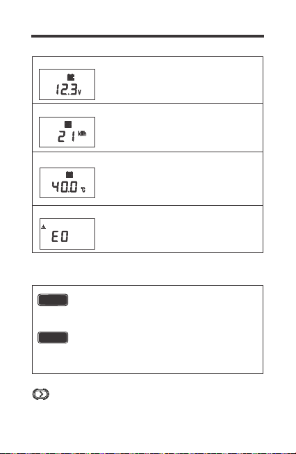
Battery Voltage is displayed indicated by
Batt. System voltage is also displayed.
Accumulated consumption is displayed.
You may clear the contents back to 0
through the controller.
The temperature displayed is the
controller’s or the remote temperature
sensor if utilizing the accessory. The unit
is in Celsius and can not be changed to F
on the interface.
The error code is displayed only if the unit
experiences an error. If there is an error, it
will be the default screen.
Enter parameter setting mode when highlighting the
appropriate screen and pressing down on the right key.
Incorrect battery type setting may damage your
battery. Please check with your battery manufacturer’s
specifications before selecting the battery type.
If selecting Lithium, Lithium refers to Lithium
iron-phosphate and you will need to manually set
the voltage to 12V or 24V as well as choose your
charging voltage (14.4V Boost Voltage by default).
NOTE
WARNING
16
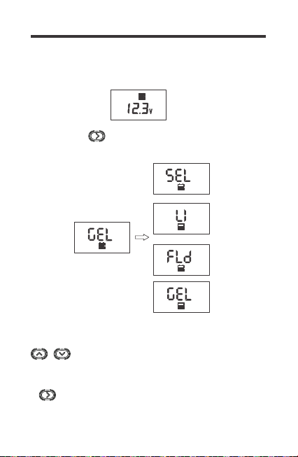
To enter battery programming settings, navigate to the Battery
Voltage Screen (below) and then press and hold the right key
button until the screen starts to flash the battery type:
Utilize the arrows to navigate through Sealed
Lead Acid / AGM (SEL), Lithium-Iron Phosphate
(Li), Flooded (FLD) and Gel (Gel).
To confirm your selection, Press and Hold the
right key. Please Note, when selecting Li, you will
have to program your 12V or 24V manually.
Battery Type
12V
BATT
12V
BATT
Press and Hold
12V
BATT
12V
BATT
12V
BATT
12V
BATT
17
Selecting Lithium
System Voltage
Enter parameter setting mode when highlighting the
appropriate screen and pressing down on the right key.
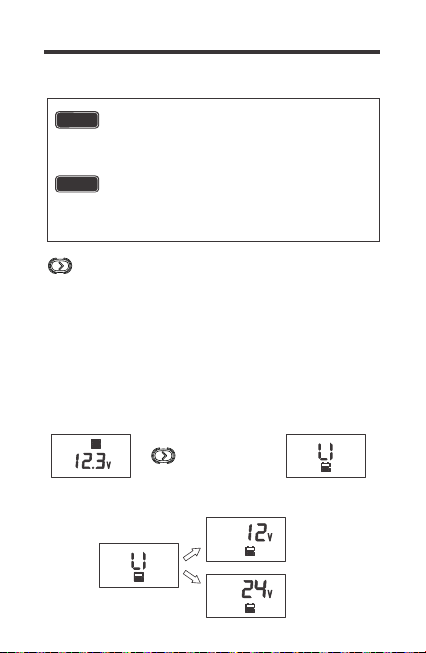
To enter battery programming settings, navigate to the Battery
Voltage Screen (below) and then press and hold the right key
button until the screen starts to flash the battery type. Navigate
the highlight Li and once LI is highlighted, tap the RIGHT button
to set your system voltage. Choose between 12 or 24V and
when satisfied, tap the RIGHT button to enter Boost Voltage
Programming.
Battery Type
12V
BATT
Incorrect battery type setting may damage your
battery. Please check with your battery
manufacturer’s specifications before selecting the
battery type.
If selecting Lithium, Lithium refers to Lithium
iron-phosphate and you will need to manually set
the voltage to 12V or 24V as well as choose your
charging voltage (14.4V Boost Voltage by default).
NOTE
WARNING
Press and Hold
12V
BATT
12V
BATT
12V
BATT
24V
BATT
Set Li system Voltage:
18
Lithium Battery Activation
Manual programming of 12V or 24V batteries
is only available for Li batteries. For other
battery types, the RMS-RVRE will recognize the
Rover’s Elite’s auto recognition system voltage
and adjust accordingly.
The Rover Elite MPPT charge controller has a reactivation
feature to awaken a sleeping lithium battery. The protection
circuit of lithium battery will typically turn the battery off and
make it unusable if over-discharged. This can happen when
storing a lithium battery pack in a discharged state for any
length of time as self-discharge would gradually deplete the
remaining charge. Without the wake-up feature to reactivate
and recharge batteries, these batteries would become
unserviceable and the packs would be discarded. The Rover
Elite will apply a small charge current to activate the protection
circuit and if a correct cell voltage can be reached, it starts a
normal charge. Lithium Battery Activation.
NOTE
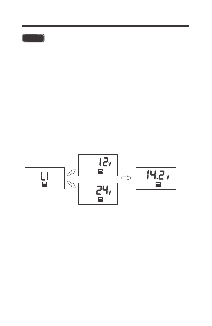
Set Li Boost Voltage:
By default, the boost voltage will be 14.4V for Li. Once in the
Boost Voltage screen, you can navigate in increments of 0.2V
to set your appropriate boost voltage. Press the UP/DOWN
arrows to change the boost voltage. You may select values
between 12.6V ~ 16.0V.
To confirm your selection, Press and Hold the right key to
confirm the parameters set.
System Voltage
Boost Voltage
Battery Type
12V
BATT
12V
BATT
24V
BATT
24V
CHG
BATT
19
Troubleshooting
If the Rover Elite is not functioning properly, it will display an
error code not normally seen in the interface display.
Depending on the code, you may attempt to troubleshoot the
error to commence normal system operation.
Error Codes / Troubleshooting
System behaving normally, no action
needed. You will not see this error code.
Use a multi-meter to get a reading of the
battery voltage in volts DC to validate
error code. Battery is very low.
Disconnect any loads to the battery and
let the solar system charge the battery
backup. If the battery voltage is low it
may be in open battery protection mode,
which is a Rover Elite Protection.
Make sure controller is in ventilated area
and that the appropriate wire sizes are
used to connect to and from the
controller. This may be creating heating
issues inside the controller. The
controller will resume normal operation
upon cooling down.
Use a multi-meter to get a reading of the
battery voltage in volts DC to validate
error code. Battery is charging very high
and approached 16VDC. Disconnect any
external chargers and isolate which
charger is overcharging battery.
Eliminate from system.
E0
E01
E02
E06
Error
Code
Meaning
Troubleshoot
No Error
Over-
discharged
battery
Battery
Over-
charging
Controller
internals
over
temperature
20
Record the ambient temperature found in
the controller screen. Make sure the
controller is not placed in direct line of
heating sources or that it is over-heating
due to over-sun exposure. The controller
will resume normal operation upon
cooling down.
The controller has a maximum dc voltage
input of 100DC. If connecting your panels
in series, make sure the reading does not
go over this limit. Check with a multi-meter
before connecting to the controller to
ensure you’re within this specification. This
might require using less panels.
The battery cables are reversed. Use a
multi-meter to make sure your voltage
reading has the correct polarity (Red to
positive and Black to negative) with a
positive number in volts DC. If the number
is negative, switch the positive and
negative battery cables in the battery
terminal of the Rover Elite.
The solar panel wires are connected in
reverse polarity. Verify using a
multi-meter to make sure your voltage
reading has the correct polarity with a
positive number in volts DC.
E10
E13
E07
E14
PV Over-
voltage
PV reverse-
polarity
Controller is
over-
temperature
Battery
reverse
polarity
Protection Behaviors / Fixes
If the Rover Elite is not functioning properly and is not displaying
an error code, it may be undergoing an automatic protection
function. This does not mean your Rover Elite is defective, but it
requires some troubleshooting to commence normal system
operation.
21
Behavior Protective Function / Fixes
Reverse Battery Polarity Protection
The Rover Elite needs a correct battery
connection to startup. This might mean that
the battery cables are reversed. Use a
multi-meter to make sure your voltage reading
has the correct polarity (Red to positive and
Black to negative) with a positive number in
volts DC. If the number is negative, switch the
positive and negative battery cables in the
battery terminal of the Rover Elite.
The solar panel wires are connected in
reverse polarity. Verify using a multi-meter to
make sure your voltage reading has the
correct polarity with a positive number in volts
DC. In some cases, with the battery and solar
panels both connected in reverse polarity, the
controller will not turn on, but the controller is
not damaged. Simply correct the reverse
polarity to continue normal operation.
The controller has a maximum dc voltage
input of 100DC. If connecting your panels in
series, make sure the reading does not go
over this limit. Check with a multi-meter before
connecting to the controller to ensure you’re
within this specification. This might require
using less panels to make sure you are within
the Rover Elite specified input.
The battery is
connected to
thecontroller,
but the
controller is
not turning on
The battery
and solar
panels are
connected to
the controller,
but the
controller
shows
nighttime.
When
connecting
solar panels
to the
controller it
sounds an
alarm
Solar Panels Reverse Polarity Protection
Solar Panels Over voltage
22
If the battery was charging fine and stopped,
it could be because it was being overcharged
by the solar source if not an external source.
You might see an E02 display or perhaps an
empty screen. Make sure your charging
sources are not charging at 16VDC or check
to see if your batteries are being equalized,
an intentional over-charging, that might be
triggering this error.
The max amp charging from the Rover Elite
will be the respective amp rating. The Rover
Elite will current limit any excess amperage
than the rating of the controller, however, be
cautious as this might create excess heat and
put the controller in an internal/external
temperature protection mode which will halt
the controller performance until it can cool
down and function normally again.
Whether connecting the system for the first
time or operating it for a while, you may
experience an E01 error if the controller does
not actually detect a battery and assumes it to
be under-discharged. This can happen in an
accidental line break or failure to connect it
correctly the first time. This will not damage
the controller, but you will need to make sure
the battery voltage is the same as the battery
terminal voltage or check for continuity. Once
fixed, normal operation should continue.
The charge
controller
believes
the battery is
over-
discharged,
but it is not
Current
Limiting /
Temperature
Protection
My system
stopped
charging
E02 Battery Overcharging
Current Limiting / E06 / E07
Open Battery Protection Mode

Maintenance
For best controller performance, it is recommended that these
tasks be performed from time to time.
1.Check wiring going into the charge controller and make sure
there is no wire damage or wear.
2.Tighten all terminals and inspect any loose, broken, or burnt up
connections.
3.Occasionally clean the case using a damp cloth.
23
24
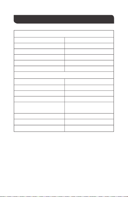
Technical Specifications
Electrical Specifications
Mechanical Specifications
Supply Voltage
Supply Current
Power Consumption
Operating Temperature Range
Voltage Accuracy
Current Accuracy
Communication Port
Display
User Interface
Mounting System
Weight
Mounting Screw
RJ45 (RS485 Protocol)
Backlit LCD
4 Front Panel Menu Buttons
Wall Mount
2.8 x 4.3 x 1.3 inch /
70 x 110 x 31.8 mm
0.14 lbs / 62 g
M2.9x13
5VDC
30mA
<1W
-4℉~113℉/ -20℃~ 45℃
±0.1V
±0.1A
Dimension
Wire Length
16.4 ft / 5 m
25
Battery Charging Parameters
Battery FLOODED LI(LFP)
High Voltage
Disconnect
Over Voltage
Reconnect
16 V 16 V
15 V 15 V
Equalization
Voltage
-----
Boost Charge
Voltage
Float Charge
Voltage
13.8 V -----
Boost Return
Voltage
13.2 V 13.2 V
Over-discharge
Recover
12.6 V 12.6 V
Over-discharge
Warning
11.1 V 11.1 V
Equalization
Interva
30 Days
Equalization
Duration
Boost Duration
2 hours
2 hours
-----
-----
-----
14.8V
14.6 V
SLD/AGM
16 V
15 V
-----
-----
-----
13.8 V
13.2 V
12.6 V
11.1 V
14.6 V
GEL
16 V
15 V
-----
-----
-----
13.8 V
13.2 V
12.6 V
11.1 V
2 hours2 hours
14.2 V
14.4V
User:
12.6V-16V

26
This equipment has been tested and found to comply with the
limits for a class B digital device, pursuant to part 15 of the FCC
Rules. These limits are designed to provide reasonable
protection against harmful interference in a residential
installation. This equipment generates, uses and can radiate
radio frequency energy and if not installed and used in
accordance with the instructions, may cause harmful
interference to radio communications. However, there is no
guarantee that interference will not occur in a particular
installation. If this equipment does cause harmful interference to
radio or television reception, which can be determined by turning
the equipment off and on, the user is encouraged to try to correct
the interference by one or more of the following measures:
• Reorient or relocate the receiving antenna.
• Increase the separation between the equipment and receiver.
• Connect the equipment into an outlet on a circuit different from
that to which the receiver is connected.
• Consult the dealer or an experienced radio/TV technician for
help.
This device complies with Part 15 of the FCC Rules.
Operation is subject to the following two conditions:
(1) This device may not cause harmful interference.
(2) This device must accept any interference received,
including interference that may cause undesired operation.
Renogy reserves the right to change
the contents of this manual without notice.
RENOGY.COM
US
2775 E Philadelphia St, Ontario, CA 91761, USA
909-287-7111
www.renogy.com
support@renogy.com
https://www.renogy.cn
support@renogy.cn
CN
400-6636-695
苏州高新区科技城培源路1号5号楼-4
CA
https://ca.renogy.com
supportca@renogy.com
https://au.renogy.com
supportau@renogy.com
AU
JP
https://www.renogy.jp
supportjp@renogy.com
https://uk.renogy.com
supportuk@renogy.com
UK
https://de.renogy.com
supportde@renogy.com
DE