Loading ...
Loading ...
Loading ...
COIL
FACTORY SHIPPED -- BRACKET
HORIZONTAL LEFT
APPLICATION 4_.
COIL
SUPPORT
RAIL
DRAIN PAN
SUPPORT
BRACKET
COIL
BRACKET
HORIZONTAL
DRAIN PAN
PRIMARY DRAIN
AIR SEAL HORIZONTAL LEFT
ASSEMBLY SECONDARY DRAIN
HORIZONTAL LEFT
REFRIGERANT
CONNECTIONS
A00072
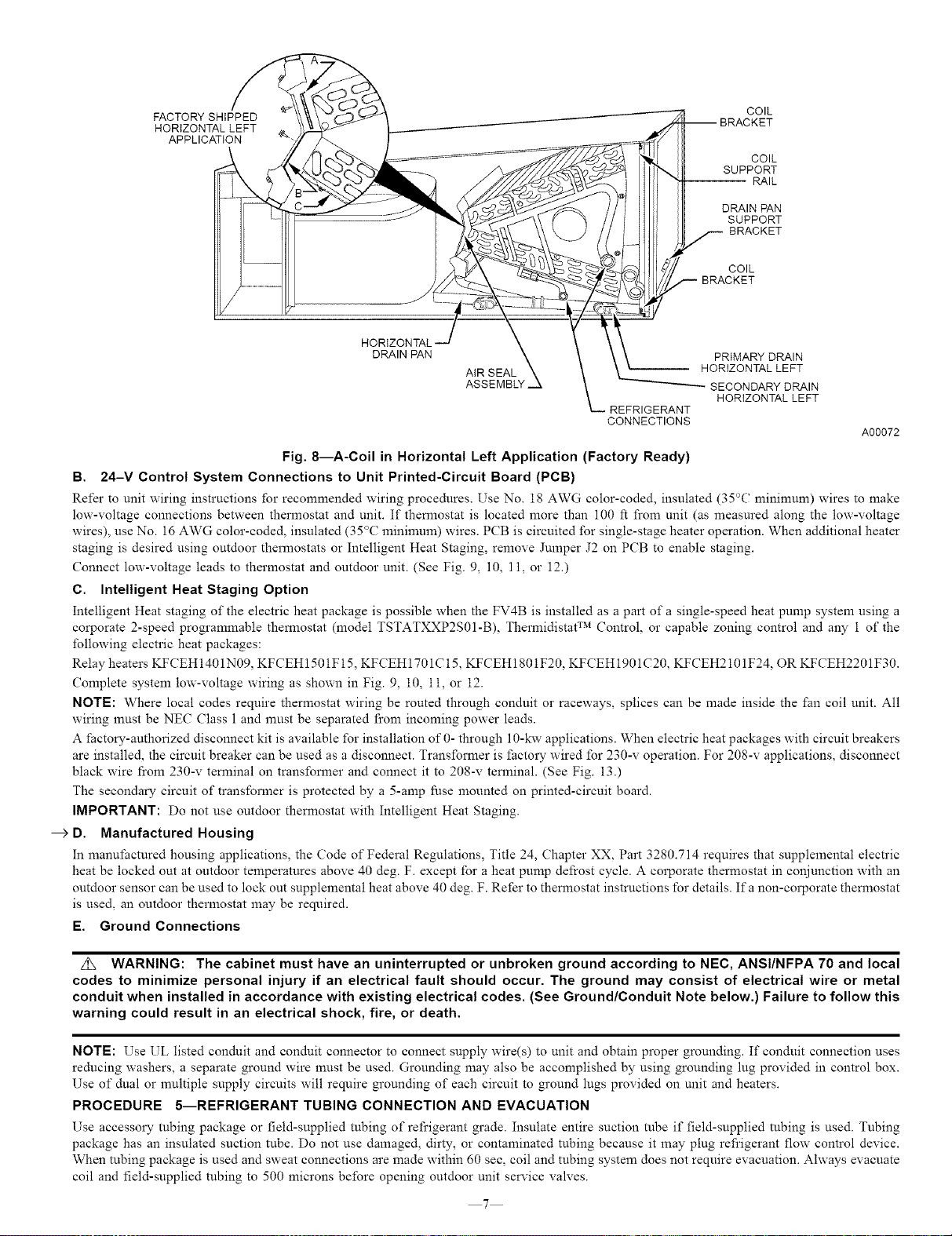
Fig. 8---A-Coil in Horizontal Left Application (Factory Ready)
B. 24-V Control System Connections to Unit Printed-Circuit Board (PCB)
Refer to unit wiring instructions for recommended wiring procedures. Use No. 18 AWG color-coded, insulated (35°C mininmm) wires to make
low-voltage connections between thermostat and unit. If thermostat is located more than 100 ft from unit (as measured along the low-voltage
wires), use No. 16 AWG color-coded, insulated (35°C minimum) wires. PCB is circuited for single-stage heater operation. When additional heater
staging is desired using outdoor thermostats or Intelligent Heat Staging, remove Jnmper J2 on PCB to enable staging.
Connect low-voltage leads to thermostat and outdoor unit. (See Fig. 9, 10, 11, or 12.)
C. Intelligent Heat Staging Option
Intelligent Heat staging of the electric heat package is possible when the FV4B is installed as a part of a single-speed heat pump system using a
corporate 2-speed programmable thermostat (model TSTATXXP2S01-B), Thermidistat TM Control, or capable zoning control and any 1 of the
following electric heat packages:
Relay heaters KF(TEH 1401N09, KFCEH 1501F 15, KFCEH 1701C 15, KFCEH 1801 F20, KFCEH 1901 C20, KFCEH2101 F24, OR KFCEH2201F 30.
Complete system low-voltage wiring as shown in Fig. 9, 10, 11, or 12.
NOTE: Where local codes require thermostat wiring be routed through conduit or raceways, splices can be made inside the tim coil unit. All
wiring must be NEC Class 1 and must be separated l}om incoming power leads.
A _actory-authorized disconnect kit is available for installation of 0- through 10-kw applications. When electric heat packages with circuit breakers
are installed, the circuit breaker can be used as a disconnect. Transformer is fi_ctory wired for 230-v operation. For 208-v applications, disconnect
black wire l}om 230-v terminal on transformer and connect it to 208-v terminal. (See Fig. 13.)
The secondary circuit of transformer is protected by a 5-amp fuse mounted on printed-circuit board.
IMPORTANT: Do not use outdoor thermostat with Intelligent Heat Staging.
--_ D. Manufactured Housing
In manufactured housing applications, the Code of Federal Regulations, Title 24, Chapter XX, Part 3280.714 requires that supplemental electric
heat be locked out at outdoor temperatures above 40 deg. F. except for a heat pump defrost cycle. A corporate thermostat in conjunction with an
outdoor sensor can be used to lock out supplemental heat above 40 deg. F. Refer to thermostat instructions for details. Ifa non-corporate thermostat
is used, an outdoor thermostat may be reqnired.
E. Ground Connections
z_ WARNING: The cabinet must have an uninterrupted or unbroken ground according to NEC, ANSI/NFPA 70 and local
codes to minimize personal injury if an electrical fault should occur. The ground may consist of electrical wire or metal
conduit when installed in accordance with existing electrical codes. (See Ground/Conduit Note below.) Failure to follow this
warning could result in an electrical shock, fire, or death.
NOTE: Use UL listed conduit and conduit connector to connect supply wire(s) to unit and obtain proper grounding. If conduit connection uses
reducing washers, a separate ground wire must be used. Grounding may also be accomplished by using grounding lug provided in control box.
Use of dual or multiple supply circuits will reqnire grounding of each circuit to ground lugs provided on unit and heaters.
PROCEDURE 5--REFRIGERANT TUBING CONNECTION AND EVACUATION
Use accessory tubing package or field-supplied tubing of refrigerant grade. Insulate entire suction tube if field-supplied tubing is used. Tubing
package has an insulated suction tube. Do not use damaged, dirty, or contaminated tubing because it may plug refrigerant flow control device.
When tubing package is used and sweat connections are made within 60 sec, coil and tubing system does not require evacuation. Ahvays evacuate
coil and field-supplied tubing to 500 microns before opening outdoor unit service valves.
7
Loading ...
Loading ...
Loading ...