Loading ...
Loading ...
Loading ...
3. SYSTEM TYPE - Select system type HP-COMFORT (for heat pump system) or AC (for air conditioner system).
4. ACiHP CFM ADJUST - Select LO.
5. ON/OFF DELAY - Select ENH profile.
6. CONTINUOUS FAN - Select desired fan speed when thermostat is set to continuous tim.
7. If the fan coil is installed with Intelligent Heat Staging capable electric heaters, remove jumper J2. (See Fig. 17.)
NOTE: If configuring to run warmer heating, do not remove jumper J2 when using 5-, 8-, or 10-kw heaters.
8. Remove jumper J1 to activate dehumidify modes.
9. Wire low voltage connections as shown in Fig. 9, 10, 11, or 12.
10. Configure Themfidistat (or capable zoning system) following its installation instructions for enhanced dehumidification and
SuperComfortiPerfect Heat operation.
This configuration provides the following comfort enhancements:
a. A 30 second blower on delay with 150 seconds at 70 percent airflow to allow the indoor coil to warm up or cool down before the blower
is asked to deliver I00 percent airflow reducing the cold blow sensation at start up in heating and allowing the indoor coil to more qnickly
reach wet coil operating conditions in cooling.
b. No blower off delay eliminates cold blow which may be associated with running the blower after shut down of the compressor and avoids
re-evaporation of condensed moisture after cooling/dehumidifying operation.
c. Lower airflow while the compressor is running to reduce &aft effects and increase heating air temperature and improved humidity control
during cooling operation.
d. Intelligent Staging of the electric heater elements to more closely match heating load requirements and provide more consistent heating
air temperatures.
PROCEDURE 9--ACCESSORY INSTALLATION
A. Accessory Electric Heaters
Electric heaters may be installed with the FV4B Fan Coil per instructions supplied with electric heater package. See unit rating plate for
fi_ctory-approved electric heater kits.
NOTE: Units installed without electric heat should have a field-supplied sheet metal block-offplate covering the heater opening. This reduces
air leakage and formation of exterior condensation.
B. Auxiliary Terminals
The AUX and HUM terminals on the Easy Select Board are tied directly to the G temfinal, and provide a 24-vac signal whenever the G terminal
is energized. (See Fig. 17 and 18.) During Super Dehumidify and SuperComfort Perfect Heat modes, the G signal is not present and the auxiliary
terminals are not energized. If the installation includes the use of these operating modes, do not use these temfinals to control accessories. See
Electronic Air Cleaner and Humidifier sections for further information.
C. Electronic Air Cleaner Connections
The AUX1 and AUX2 terminals are not ahvays energized during blower operation, as described above. When using an electronic air cleaner with
the FV4B Fan Coil, use Airflow Sensor Part No. KEAAC0101AAA. The airflow sensor turns on electronic air cleaner when the fan coil blower
is operating.
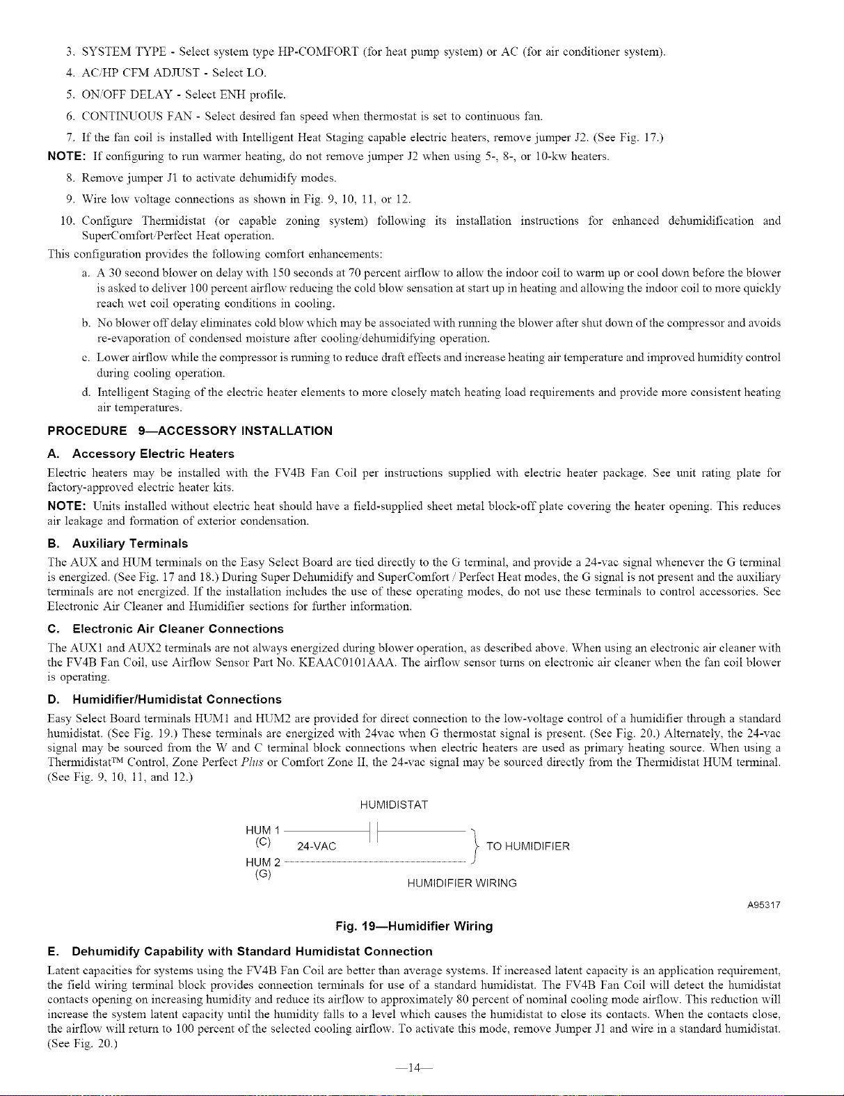
D. Humidifier/Humidistat Connections
Easy Select Board terminals HUM1 and HUM2 are provided for direct connection to the low-voltage control of a humidifier through a standard
humidistat. (See Fig. 19.) These terminals are energized with 24vac when G thermostat signal is present. (See Fig. 20.) Alternately, the 24-vae
signal may be sourced from the W and C terminal block connections when electric heaters are used as primary heating source. When using a
Thermidistat TM Control, Zone Perfect Phts or Comfort Zone II, the 24-vae signal may be sourced directly from the Themfidistat HUM terminal.
(See Fig. 9, 10, i1, and 12.)
HUMIDISTAT
HUM1 It }
(C) 24-VAC TO HUMIDIFIER
HUM 2 ..................................................................................................................................................................................................................................
(G)
HUMIDIFIER WIRING
Fig. 19--Humidifier Wiring
A95317
E. Dehumidify Capability with Standard Humidistat Connection
Latent capacities for systems using the FV4B Fan Coil are better than average systems. It'increased latent capacity is an application requirement,
the field wiring terminal block provides connection terminals for use of a standard humidistat. The FV4B Fan Coil will detect the humidistat
contacts opening on increasing humidity and reduce its airflow to approximately 80 percent of nominal cooling mode airflow. This reduction will
increase the system latent capacity until the humidity falls to a level which causes the humidistat to close its contacts. When the contacts close,
the airflow will return to 100 percent of the selected cooling airflow. To activate this mode, remove Jnmper J1 and wire in a standard humidistat.
(See Fig. 20.)
14
Loading ...
Loading ...
Loading ...