Loading ...
Loading ...
Loading ...
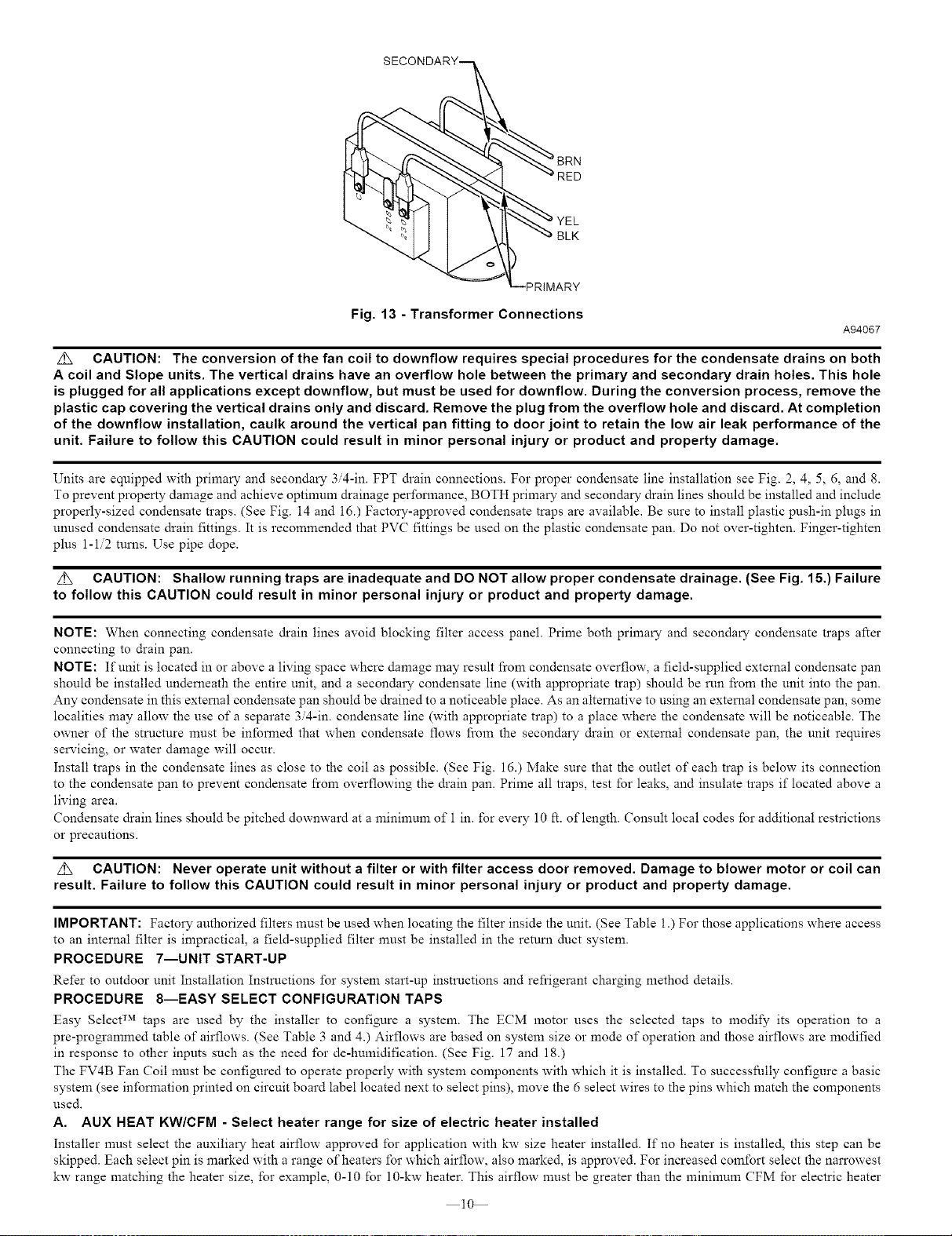
BLK
Fig. 13 - Transformer Connections
A94067
z_ CAUTION: The conversion of the fan coil to downflow requires special procedures for the condensate drains on both
A coil and Slope units. The vertical drains have an overflow hole between the primary and secondary drain holes. This hole
is plugged for all applications except downflow, but must be used for downflow. During the conversion process, remove the
plastic cap covering the vertical drains only and discard. Remove the plug from the overflow hole and discard. At completion
of the downflow installation, caulk around the vertical pan fitting to door joint to retain the low air leak performance of the
unit. Failure to follow this CAUTION could result in minor personal injury or product and property damage.
Units are equipped with primary and secondary 3/4-in. FPT &ain connections. For proper condensate line installation see Fig. 2, 4, 5, 6, and 8.
To prevent property damage and achieve optinmm drainage performance, BOTH primary and secondary drain lines should be installed and include
properly-sized condensate traps. (See Fig. 14 and 16.) Factory-approved condensate traps are available. Be sure to install plastic push-in plugs in
unused condensate drain fittings. It is recommended that PVC fittings be used on the plastic condensate pan. Do not over-tighten. Finger-tighten
plus 1-1/2 turus. Use pipe dope.
z_ CAUTION: Shallow running traps are inadequate and DO NOT allow proper condensate drainage. (See Fig. 15.) Failure
to follow this CAUTION could result in minor personal injury or product and property damage.
NOTE: When connecting condensate drain lines avoid blocking filter access panel. Prime both primary and secondary condensate traps after
connecting to drain pan.
NOTE: If unit is located in or above a living space where damage may result from condensate overflow, a field-supplied exterual condensate pan
should be installed underueath the entire unit, and a secondary condensate line (with appropriate trap) should be run from the unit into the pan.
Any condensate in this exterual condensate pan should be drained to a noticeable place. As an alternative to using an exterual condensate pan, some
localities may allow the use of a separate 3/4-in. condensate line (with appropriate trap) to a place where the condensate will be noticeable. The
owner of the structure must be inlbrmed that when condensate flows from the secondary &ain or external condensate pan, the unit requires
servicing, or water damage will occur.
Install traps in the condensate lines as close to the coil as possible. (See Fig. 16.) Make sure that the outlet of each trap is below its connection
to the condensate pan to prevent condensate from overflowing the &ain pan. Prime all traps, test for leaks, and insulate traps if located above a
living area.
Condensate drain lines should be pitched downward at a minimum of 1 in. for every 10 It. of length. Consult local codes lbr additional restrictions
or precautions.
z_ CAUTION: Never operate unit without a filter or with filter access door removed. Damage to blower motor or coil can
result. Failure to follow this CAUTION could result in minor personal injury or product and property damage.
IMPORTANT: Factory authorized filters must be used when locating the filter inside the unit. (See Table 1.) For those applications where access
to an internal filter is impractical, a field-supplied filter must be installed in the returu duct system.
PROCEDURE 7--UNIT START-UP
Refer to outdoor unit Installation Instructions for system start-up instructions and refrigerant charging method details.
PROCEDURE 8--EASY SELECT CONFIGURATION TAPS
Easy Select TM taps are used by the installer to configure a system. The ECM motor uses the selected taps to modify its operation to a
pre-programmed table of airflows. (See Table 3 and 4.) Airflows are based on system size or mode of operation and those airflows are modified
in response to other inputs such as the need for de-humidification. (See Fig. 17 and 18.)
The FV4B Fan Coil must be configured to operate properly with system components with which it is installed. To successlMly configure a basic
system (see infonnation printed on circuit board label located next to select pins), move the 6 select wires to the pins which match the components
used.
A. AUX HEAT KW/CFM - Select heater range for size of electric heater installed
Installer must select the auxiliary heat airflow approved for application with kw size heater installed. If no heater is installed, this step can be
skipped. Each select pin is marked with a range of heaters for which airflow, also marked, is approved. For increased comfort select the narrowest
kw range matching the heater size, for example, 0-10 for 10-kw heater. This airflow must be greater than the minimum CFM Ibr electric heater
10
Loading ...
Loading ...
Loading ...