Loading ...
Loading ...
Loading ...
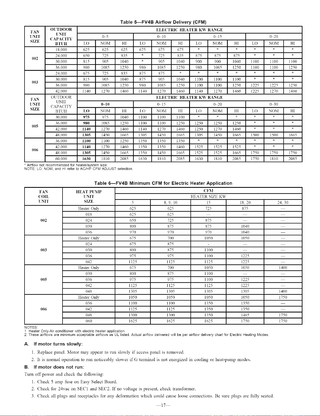
Table 5--FV4B Airflow Delivery (CFM)
OUTDOOR ELECTRIC HEATER K'W 1L&NGE
FAN
(NIT
UNIT 0 5 0 10 0 15 0 20
(APA(ITY
SIZE
BTITH LO NOM HI LO NOM HI LO NOM HI LO NOM HI
18.000 625 625 625 675 675 675 * * * * * *
24.000 650 725 835 * 725 835 875 875 875 * * *
002
30.000 815 905 1040 * 905 1040 900 900 1040 1100 11% 1100
36.000 980 1085 1250 980 1085 1250 980 1085 1250 1100 1100 1250
24,000 675 725 835 875 875 * * * * * * *
30.000 815 905 1040 875 905 1040 1100 1100 11% * * *
003
36.000 980 1085 1250 980 1085 1250 1100 1100 1250 1225 1225 1250
42.000 1t40 1270 1460 1140 1270 1460 1140 1270 1460 1225 1270 1460
OUTDOOR ELECTRIC HEATER K_V 1K4.NGE
FAN
LLNIT
UNIT 0-10 0 15 020 030
CAPACITY
SIZE
BTUH LO NOM HI LO NOM HI LO NOM HI LO NOM HI
30.000 975 975 1040 1100 1t00 1100 * * * * * *
36.000 980 1085 1250 1100 1100 1250 1250 1250 1250 * * *
005
42.000 1140 1270 1460 1140 1270 1460 1250 1270 1460 * * *
48.000 1305 1450 1665 1305 1450 1665 1305 1450 1665 1500 1500 1665
36.000 1100 1100 1250 1350 1350 1350 * * * * * *
42.000 1140 1270 1460 1350 1350 1460 1525 1525 1525 * * *
006
48.000 1305 1450 1665 1350 1450 1665 1525 1525 1665 1750 1750 1750
60.000 1630 1810 2085 1630 1810 2085 1630 1810 2085 1750 1810 2085
• Airflow not recommended for heater/system size.
NOTE: LO, NOM, and HI refer to AC/HP CFM ADJUST selection
Table 6--FV4B Minimum CFM for Electric Heater Application
FAN
COIL
INIT
002
003 1100
1100
1125
1050
11%
005 1100
1125
1305
1050
1350
006 1350
1350
1625
HEAT PIMP
UNIT
SIZE
Heater Only
018
024
030
036
Heater Only
024
030
036
042
Heater Only
030
036
042
048
Heater Only
036
042
048
06O
NOTES:
1HeaterOnly-Airconditionerwithelectricheaterapptication.
5
625
625
650
800
970
675
675
800
975
1125
675
800
975
1125
1305
1050
1100
1125
1300
1625
8. 9. 10
625
625
725
875
970
700
875
875
975
1125
700
875
975
1125
1305
1050
1100
1125
1300
1625
(FM
HEATER SIZE KW
15
725
875
875
970
1050
18. 20
875
1040
1040
1050
1225
1225
1050
1225
1225
1305
1050
1350
1350
1465
1750
2 These airflows are minimum acceptable airflows as UL Iisted Actual airflow deIivered wili be per airflow delivery chartfor EIectric Heating Modes.
A. If motor turns slowly:
l. Replace panel. Motor may appear to run slowly if access panel is removed.
2. It is normal operation to run noticeably slower if G terminal is not energized in cooling or heat-pump modes.
B. If motor does not run:
Turn off power and check the following:
1. Check 5 amp fl_se on Easy Select Board.
2. Check l'or 24vac on SECI and SEC2. If no voltage is present, check transformer.
3. Check all plugs and receptacles for any deformation which could cause loose connections. Be sure plugs are fully seated.
17
24. 30
1400
1400
1750
1750
1750
Loading ...
Loading ...
Loading ...