Loading ...
Loading ...
Loading ...
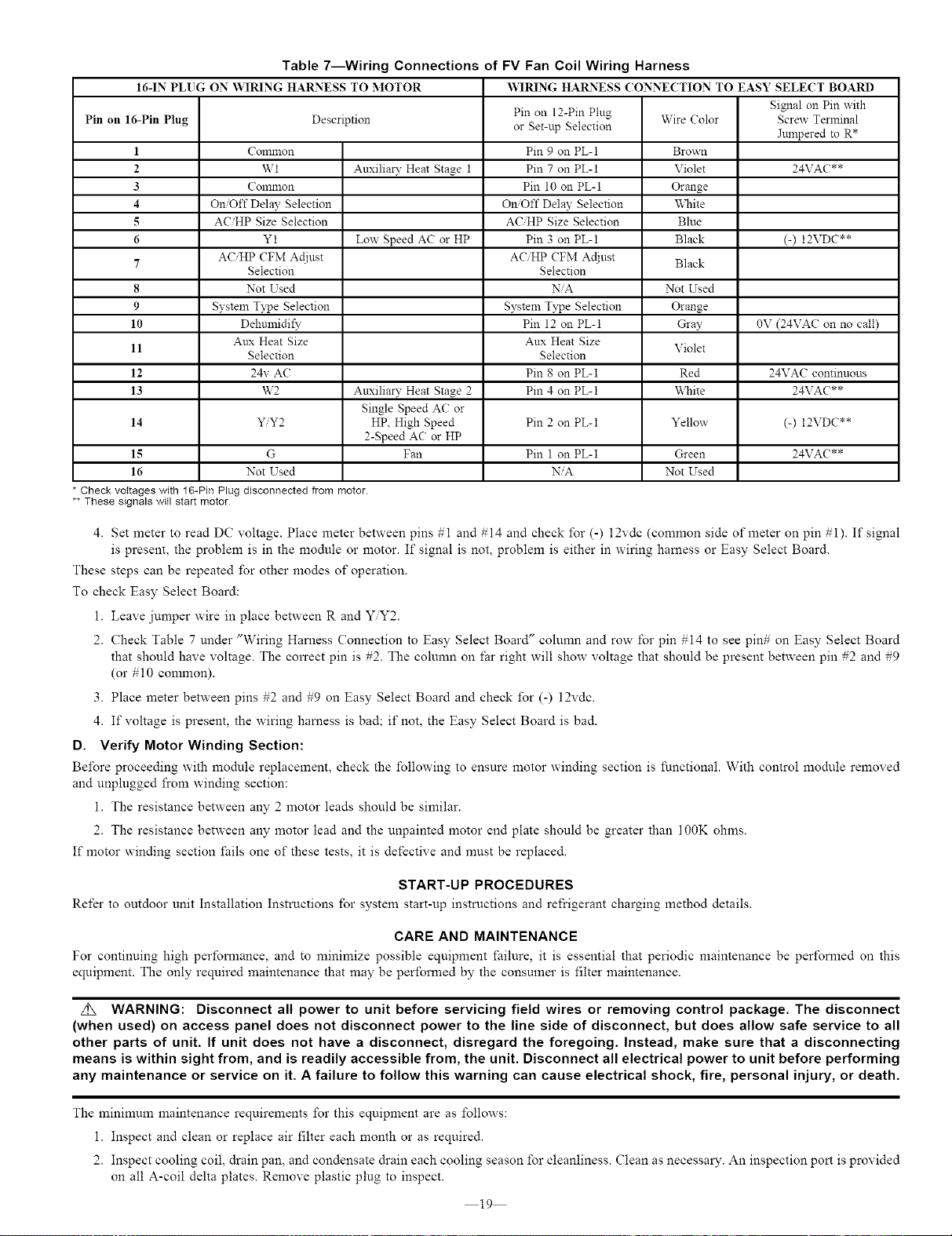
Table 7---Wiring Connections of FV Fan Coil Wiring Harness
16-IN PLUG ON WIRING HA1LNESS TO MOTOR _][RING HARNESS (ONNE(TION TO EASY SELECT BOARD
Pin on 16-Pin Plug Description
1 Common
2 W1
3 Common
4 On/Off Delay Selection
5 ACiHP Size Selection
6 Y1
ACiHP CFM Actiust
7
Selection
8 Not Used
9 System T3_peSelection
10 Dehmnidify
Aux Heat Size
11
Selection
12 24v AC
13 W2
14 Y/Y2
15 G
16 Not Used
Check voItages with 16-Pin Plug disconnected from motor.
These signals will start motor
Signal on Pin with
Pin on 12-Pin Plug Wire Color Screw Terminal
or Set-up Selection
Jnmpered to R*
Pin 9 on PL-1 Brown
Anxilia_" Heat Stage 1 Pin 7 on PL-1 Violet 24VAC**
Pin 10 on PL-1 Orange
On/Off Delay Selection White
ACiHP Size Selection Blue
Low Speed AC or HP Pin 3 on PL-1 Black (-) 12VDC**
ACHP CFM Adiust Black
Selection
NiA Not Used
System Type Selection Orange
Pin 12 on PL-1 Gray 0V (24VAC on no call)
Aux Heat Size
Violet
Selection
Pin 8 on PL-1 Red 24VAC continuous
Anxilia_" Heat Stage 2 Pin 4 on PL-1 White 24VAC**
Single Speed AC or
HP. High Speed Pin 2 on PL-1 Yellow (-) 12VDC**
2-Speed AC or HP
Fan Pin 1 on PL-1 Green 24VAC**
NiA Not Used
4. Set meter to read DC voltage. Place meter between pins #1 and #14 and check for (-) 12vdc (common side of meter on pin #1). If signal
is present, the problem is in the module or motor. If signal is not, problem is either in wiring hamess or Easy Select Board.
These steps can be repeated for other modes of operation.
To check Easy Select Board:
1. Leave jumper wire in place between R and Y/Y2.
2. Check Table 7 under "Wiring Haruess Connection to Easy Select Board" column and row for pin #14 to see pin# on Easy Select Board
that should have voltage. The correct pin is #2. The column on far right will show voltage that should be present between pin #2 and #9
(or #10 common).
3. Place meter between pins #2 and #9 on Easy Select Board and check for (-) 12vdc.
4. If voltage is present, the wiring haruess is bad; if not, the Easy Select Board is bad.
D. Verify Motor Winding Section:
Before proceeding with module replacement, check the following to ensure motor winding section is functional. With control module removed
and unplugged from winding section:
1. The resistance between any 2 motor leads should be similar.
2. The resistance between any motor lead and the unpainted motor end plate should be greater than 100K ohms.
If motor winding section fails one of these tests, it is defective and must be replaced.
START-UP PROCEDURES
Refer to outdoor unit Installation Instructions for system start-up instructions and refrigerant charging method details.
CARE AND MAINTENANCE
For continuing high perfomaance, and to minimize possible equipment failure, it is essential that periodic maintenance be performed on this
equipment. The only required maintenance that may be performed by the consumer is filter maintenance.
z_X WARNING: Disconnect all power to unit before servicing field wires or removing control package. The disconnect
(when used) on access panel does not disconnect power to the line side of disconnect, but does allow safe service to all
other parts of unit. If unit does not have a disconnect, disregard the foregoing. Instead, make sure that a disconnecting
means is within sight from, and is readily accessible from, the unit. Disconnect all electrical power to unit before performing
any maintenance or service on it. A failure to follow this warning can cause electrical shock, fire, personal injury, or death.
The mininmm maintenance requirements for this equipment are as follows:
1. Inspect and clean or replace air filter each month or as required.
2. Inspect cooling coil, drain pan, and condensate drain each cooling season for cleanliness. Clean as necessary. An inspection port is provided
on all A-coil delta plates. Remove plastic plug to inspect.
19
Loading ...
Loading ...
Loading ...