The HOW TO USE THIS MANUAL section will tell you how to find important information for ordering correct repair parts.
Parts may be ordered from authorized dealers. When placing an order for parts, the machine model and machine serial number are important. Refer to the MACHINE DATA box which is filled out during the installation of your machine. The MACHINE DATA box is located on the inside of the front cover of this manual.
The model number, serial number and RIN number locations are shown below.
The SAFETY section contains important information regarding hazardous or unsafe practices of the machine. Levels of hazards are identified that could result in product damage, personal injury, or severe injury resulting in death.
The OPERATIONS section is to familiarize the operator with the operation and function of the machine. The MAINTENANCE section contains preventive maintenance to keep the machine and its components in good working condition.
NOTE: The manual part number is located on the lower right corner of the front cover.
HAZARD INTENSITY LEVEL
There are three levels of hazard intensity identified by signal words -WARNING and CAUTION and FOR SAFETY.
The level of hazard intensity is determined by the following definitions:
WARNING - Hazards or unsafe practices which COULD result in severe personal injury or death.
CAUTION - Hazards or unsafe practices which could result in minor personal injury or product or property damage.
FOR SAFETY: To Identify actions which must be followed for safe operation of equipment.
Report machine damage or faulty operation immediately. Do not use the machine if it is not in proper operating condition. Following is information that signals some potentially dangerous conditions to the operator or the equipment. Read this information carefully. Know when these conditions can exist. Locate all safety devices on the machine. Please take the necessary steps to train the machine operating personnel.
Operations
Technical Specifications
CAUTION
This appliance is not intended for use by persons (including children) with reduced physical, sensory or mental capabilities, or lack of experience and knowledge, unless they have been given supervision or instruction concerning use of the appliance by a person responsible for their safety. Children should be supervised to ensure that they do not play with the appliance.
How This Machine Works
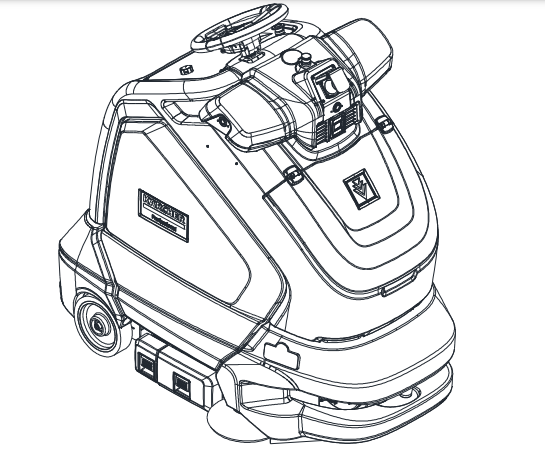
The Chariot® CV60/1 RS KIRA Autonomous is a battery powered, self-propelled, vacuum intended for commercial use. The appliance vacuums debris and dirt from the floor and collects it in the debris tray and disposable bag.
The machine's primary systems are the brush system, vacuum system, and operator control system.
The function of the brush system is to brush the floor.
The brush system consists of two cylindrical type brushes, brush motor, brush deck, side broom, side broom motor and controls. The front brush turns clockwise when viewed from the right side of the machine. The rear brush turns counterclockwise. Both brushes work to agitate the floor and to route the debris up into the brush deck. The side broom rotates counterclockwise as viewed by the operator. The side broom sweeps debris into the path of the brush deck.
The function of the vacuum system is to vacuum fine dirt and debris into the vacuum bag, and large debris into the debris tray. The vacuum system consists of the debris tray, vacuum motor, vacuum filter and vacuum bag. The debris tray captures the dirt off the floor as the machine moves forward. The vacuum motor provides suction to draw the fine dirt into the vacuum bag, and the debris tray stores large debris.
The function of the operator control system is to control the direction and speed of the machine. The directional control system consists of the direction control drive reset switch, maximum speed knob, throttle pedal, emergency stop switch, steering wheel, propel controller, and drive wheel. The directional control drive reset switch signals forward or reverse direction and makes sure the operator is on platform before machine will propel. The controller interprets signals from the maximum speed knob and the throttle pedal to command the drive wheel to propel or slow the machine. The steering wheel points the drive wheel in the direction desired by the operator. The brake automatically engages when the operator steps off the platform, turns the key off, or engages the emergency stop switch.
NOTE: Impact to machine may cause damage.
Components
1. Control Panel
2. Pedal Platform
3. Side Door Right
4. Side Door Left
5. Main Cover
6. Cover Lid
7. Brush Deck
8. Vacuum Bag
9. Side Broom
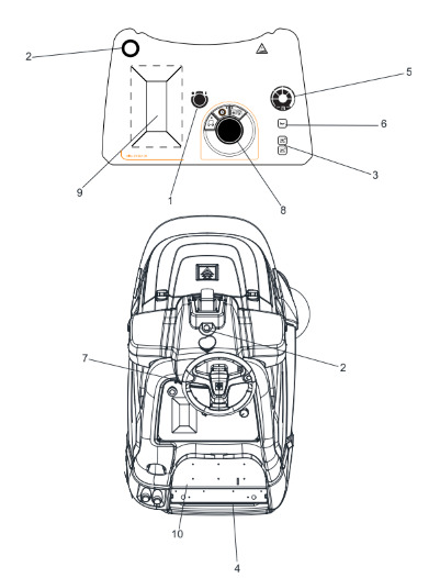
Controls
1. Key Switch
2. Emergency Stop Switch
3. Directional Control / Drive Reset Switch
4. Throttle Pedal
5. Maximum Speed Knob
6. Horn Button
7. Steering Wheel
8. Function Mode Switch
9. Display Screen
10. Operator Presence Pedal
1. Key Switch
Controls the power for machine functions. To turn the machine power on, rotate key clockwise. To turn the machine off, rotate key counterclockwise. When the key is turned on the display will come on while the system runs self-diagnostics and returns the brush deck and side broom to their raised positions, if necessary. The controller will not respond to other commands until this routine is complete.
2. Emergency Stop Switch
This safety feature is designed to cut all power to the machine at any time and apply the brake. To shut the machine power off, push the Emergency Stop Switch. This will also engage the brake and cause the machine to stop immediately. Excessive emergency stop usage can cause premature brake wear; use only when necessary. To release the emergency stop switch, rotate the switch clockwise.
3. Directional Control / Drive
Reset Switch This safety feature is designed to ensure safe engagement of propel drive. Each time the machine power is turned on, or each time an operator steps on to the platform, the Drive Reset Switch must be pushed before machine will propel. Controls the direction of travel of the vehicle. The light next to the icon on the switch indicates direction of travel. To travel forward, press the top button. To travel in reverse, press the bottom button.
4. Throttle Pedal
Controls the speed of the vehicle within the speed control setting selected, and the maximum speed knob. Pressing the pedal causes the machine to travel in the direction selected by the Directional Control Switch. To increase speed, increase pressure on the pedal. To decrease speed, decrease pressure on the pedal.
5. Maximum Speed Knob
Controls the maximum speed the machine will travel when the throttle pedal is pressed. To increase speed turn the knob clockwise. To decrease speed turn the knob counter clockwise.
6. Horn Button
The horn is activated by pressing the horn button.
7. Steering Wheel
The steering wheel turns the front wheel causing the machine to change direction.
8. Function Mode Switch
Maintenance and Settings
This mode is used to control machine settings .
Transport
This mode is used for machine transport. In this mode the machine will propel at the speed that the maximum speed knob is set to. The 'floating' brush deck and side broom are in the up position. The brushes, side broom, and vacuum are off.
Vacuuming
This mode is used for vacuuming. In this mode the machine will propel at a cleaning speed. The ‘floating’ brush deck and side broom are in the down position. The brushes will agitate, the side broom will bring debris into the path of the deck. The vacuum will draw the dirt and debris into the debris tray and the vacuum bag.
Daytime Light Vacuuming
This mode is used for daytime vacuuming. In this mode the machine will propel at a slow speed. The ‘floating’ brush deck and side broom are in the down position. The brushes will agitate, the side broom will bring debris into the path of the deck. The vacuum will draw the dirt and debris into the debris tray and the vacuum bag. The brushes, side broom, and vacuum will operate at reduced power.
Machine Operation
Pre-Run Machine Inspection
Do a pre-run inspection to find possible problems that could cause poor performance or lost time from breakdown. Follow the same procedure each time to avoid missing steps.
NOTE: Perform Pre-run Machine Check before operating machine. See Service Schedule in Maintenance Section.
Starting Machine
FOR SAFETY: Before starting machine, make sure that all safety devices are in place and operating properly.
1. The operator should be on the pedal platform. The throttle pedal must be in the neutral position.
2. Turn the machine power on by turning key switch clockwise to the “ON” position. Press the transport mode button.
3. Press the Drive Reset Directional Control Switch to set the intended direction for travel. Set the maximum speed knob to desired speed.
4. Press lightly on the throttle pedal with right foot.
Emergency Stop Procedures
1. Push in emergency stop button. This will engage the brake and cause the machine to stop immediately.
Normal Vacuuming
Plan the vacuuming pattern in advance. The longest track is around the perimeter of the area to be cleaned. For efficient operation, the runs should be the longest possible without turning or stopping.
In order to achieve the best possible results, the area which is to be cleaned should be picked up before vacuuming. Large debris, strings and wire must be removed to prevent being caught in brushes.
NOTE: Check and empty debris tray as needed during operation.
If machine is allowed to stand in neutral with the vacuum deck down for more than 2 seconds, the brush motor stops. If either forward or reverse travel is selected, the brush motor will continue once movement of machine begins. Overlap the brush path and avoid transporting over previously cleaned areas.
Recommended Path
To Begin Vacuuming
When operating the machine around people, pay close attention for unexpected movement. Use extra caution around children.
1. Stand on the operator platform. Throttle pedal must not be depressed.
2. Turn key switch to turn machine power on. Press vacuum mode button.
3. Press the Directional Control Switch to ensure that machine is set to travel in direction intended.
4. Set the maximum speed knob to desired speed. 5. Depress the throttle pedal to drive machine and turn on brushes and side broom.
To Stop Vacuuming
1. Remove foot from throttle pedal allowing pedal to return to neutral.
2. Turn machine power off or switch to transport only mode.
FOR SAFETY: Before leaving or servicing machine: stop on level surface, turn off machine and remove key.
FOR SAFETY: When using machine, go slow on inclines.
Changing Vacuum Bag
1. Park machine on level area.
2. Turn the machine power off.
3. Open cover lid.
4. Remove vacuum bag lip from nozzle.
5. Remove vacuum bag from vacuum box and dispose of properly.
6. Clean vacuum box and remove any debris.
7. Retrieve a new clean vacuum bag.
8. Place a new vacuum bag in the vacuum box and push the lip over the nozzle.
9. Close lid.
Debris Tray Removal
1. Release the debris tray lever.
2. Slide the debris tray away from machine.
Debris Tray Installation
1. Slide the debris tray into the debris tray mount notch.
2. Verify latch is fully engaged.
Maintenance
Service Schedule
Lithium Battery
This product must be recycled and is made of recycled products.
Chemical Risk
Lithium batteries are chemical risk if mis-operated, mishandled or abused.
Do:
Do protect terminals from short circuit before, during, and after installation
Do wear electrically insulated gloves
Do use electrically insulated tools
Do wear eye protection
Do wear safety toe boots / shoes
Do handle battery carefully
Do secure battery safely
Do always assume battery terminals are energized
Do Not:
Do not lift or carry the battery during usage or operation
Do not operate or store battery outside of operating limits
Do not short circuit battery
Do not puncture battery
Do not expose battery to flames, or incinerate
Do not open battery case or dissemble battery
Do not wear rings, watches, bracelets or necklaces when handling or working near battery
Do not drop or crush battery
Do not lift battery by the terminal cables
Do not vibrate battery
Do not expose battery to water or other fluids
Do not expose battery to direct sunlight
Do not dispose of battery
Do not connect with other types of batteries
Do not expose battery to high temperatures
Do not install with other battery types or brands
Transportation
If the battery is not installed in equipment, it must be transported in the original package or equivalent. Batteries are tested according to UN Handbook of Tests and Criteria, part III, sub section 38.3 (ST/SG/AC. 10/11/ Rev.5). For transport, the batteries belong to category UN3480, Class 9, Packaging Group II.
Operating
Limits The battery should not be operated outside these operating limits:
Do not install batteries in series. Select the appropriate AES battery model for the voltage of your system.
NOTE: Intentional bypassing of BMS to operate battery outside maximum and minimum limits voids warranty.
Handling
Read Safety Section before installing the battery.
Battery should be off.
Battery cables should be disconnected.
Battery terminals should be protected.
Battery handle should be used to lift battery.
Battery should be handled by two people or mechanical lift equipment.
Do not lift or carry the battery during usage or operation.
Installation - Single Battery
Read Safety Section before installing the battery.
Tools
Insulated tools sized to match nuts, bolts and cables in use
Voltmeter
Post cleaner and wire brush
Personal protective equipment
Securing Battery
Battery can be strapped in place with non-conductive nylon straps
Battery may have hold down brackets at the base of the battery
Installation
Check that battery is switched off
If battery circuit has disconnect, open disconnect to isolate battery
Clean cable connections. Broken, frayed, brittle, kinked or cut cables should be replaced
Install and secure new battery. Be careful not to ground the terminals to any metal mounting, fixture, or body part
Connect battery cables. Connect ground cable last to avoid sparks
Recommended terminal torque is 9.0 Nm (6.64 ftlb)
Close circuit disconnect (if open)
Turn battery switch on
NOTE: All cable ends must be connected to battery terminals without any washers between terminal bushings and cable ends.
Terminal burnout is caused by:
Discharge currents exceeding allowable limits
Improper cable installation
Improper cable sizing
Improper terminal torque
NOTE: Without exception, product experiencing terminal burnout will not be warranted.
NOTE: Review operating limits.
On–Off
To turn the battery on press and hold switch for 2-3 seconds
To turn the battery off press and hold switch for 2-3 seconds
Charging
Before operating the charger make sure to read and understand the instructions that come with the charger. Never attempt to charge a battery without first reviewing and understanding the instructions for the charger being used
Always make sure the chargers charging curve meets the battery’s charging requirement; never charge a visibly damaged battery; never charge a frozen battery.
1. Open doors.
2. Turn off main breaker.
3. Plug in charger to wall.
4. Turn the battery on (if required).
NOT ALL CHARGERS ARE CAPABLE OF CHARGING LITHIUM BATTERIES! During system design CONFIRM that your chosen charger is not capable of transient spikes that exceed the published MAXIMUM TERMINAL RATINGS of the battery
Storage
Systems should be stored out of direct sunlight under the following temperature conditions:
Minimum Storage Temperature -20°C / -4°F
Maximum Storage Temperature 45°C / 113°F
System should be put into storage at 80% SOC and checked monthly to ensure the system SOC (state of charge) does not fall below 20%/ At 2-% SOC the battery will self discharge in approximately 2 months.
Maintenance
CORRECTIVE ACTIONS
High Temperature
Stop discharge or charge Leave the battery to cool
Low Temperature
Stop discharge or charge
High Voltage
If charging, stop charge
Low Voltage
Do not discharge the battery. Any discharge current detected will force the battery into Low Voltage Fault The user can charge the battery in Low Voltage Recovery If no charge current is detected within 2 minutes, the BMS will turn off the battery
Over Current
Reduce current
Low SOC
Stop discharge Charge the battery
Troubleshooting
High Temperature
Stop discharge or charge
Leave the battery to cool
Low Temperature
Stop discharge or charge
High Voltage
If charging, stop charge
Low Voltage
Do not discharge the battery. Any discharge current detected will force the battery into Low Voltage Fault
The user can charge the battery in Low Voltage Recovery
If no charge current is detected within 2 minutes, the BMS will turn off the battery
Battery Won’t Turn On:
Symptom
Does the battery turn on for a short time, then turn itself off?
Description
The battery is likely in a low voltage or low SOC.
Action
Connect to charger and turn on the battery.
Symptom
Was the battery left on or stored for extended periods of time?
Description
The battery will turn itself off at 5% SOC. If left sitting at a low SOC, the battery may have discharged itself completely and cannot be used.
Action
Do not use. Replace and recycle
Service & Maintenance
Batteries should be carefully inspected on a regular basis in order to detect and correct potential problems before they can do harm. This routine should be started when the batteries are first received.
Inspection
Look for cracks in the case
Check the battery, terminals and connections to make sure they are clean, free of dirt, fluids and corrosion
All battery cables and their connections should be tight, intact, and NOT broken or frayed
Replace any damaged batteries
Replace any damaged cables
Check torque on terminal bolts
Changing Battery
Stop the machine in a clean area. Turn off machine.
FOR SAFETY: Before leaving or servicing the machine; stop on level surface, turn off machine and remove key.
Remove doors.
Use the proper size open end wrench to disconnect main ground wire first and secure cable terminal away from battery.
Disconnect main positive lead and secure cable terminals away from battery.
Prepare a suitable site to place the battery.
Attach suitable battery lifting device and lift battery from the machine. Batteries are a potential environmental hazard. Consult your battery supplier for safe disposal methods.
Recycling and Disposal
Batteries must not be mixed with domestic or industrial waste. Discover’s Advanced Energy Systems are recyclable and must be processed through a recognized recycling agency or dealer. Please contact Discover® or your servicing dealer for details.
Brush Removal & Bearing Cleaning
NOTE: The brushes should wear evenly side to side. Brushes should be replaced as a set when bristle length wears.
The brushes are removed from the right side of the machine.
Pull door lever to release latch.
Slide the brush tray out the side. Remove brush from tray.
Remove bearing cap from end of brush.
Clean bearings and cap.
Brush Installation
Place brush in tray.
Slide brush tray into opening and onto drive shaft. Make sure it is fully seated and is driven by the deck system.
Ensure the brush tray latch is fully engaged.
Side Broom Removal
1. Rotate the side broom to align pin with vertical slot.
2. Slide side broom down from assembly.
3. Reverse process to assemble.
Circuit Protection
Circuit Breakers
1. MAIN CIRCUIT BREAKER
Interrupts the flow of power from batteries in the event of an electrical overload. When the circuit breaker is tripped, it can be reset by pressing the toggle switch. If the circuit breaker continues to trip, the cause of the electrical overload must be corrected. Call for service.
Drive Motor
1. Drive Motor
2. Brake
No power to machine
Battery disconnected
Check all battery cable connections; replace or tighten as necessary.
Emergency shut-off activated
Reset
Faulty key switch
Replace switch
Battery cables corroded
Clean connections
On board charger plugged in
Unplug and stow cord
Main circuit breaker tripped
Reset circuit breaker
Little or no propel
Low battery charge
Charge batteries
Tripped circuit breaker
Reset circuit breaker and check brushs
Controller overheated
Allow cool down period
Loose motor connection
Check wires and connections from controller to motor, replace or tighten as necessary.
Faulty throttle circuit or potentiometer
Check wires and connections from throttle to controller and potentiometer resistance, replace or tighten as necessary.
Faulty platform circuit or switch
Check wires, connections and switch, replace or tighten as necessary
Machine does not change speeds
Faulty speed control circuit or switch
Check wires, connections and switch, replace or tighten as necessary.
Vacuum motor does not run, or runs slowly
Faulty vacuum circuit or switch
Check wires connections and motor, replace or tighten as necessary.
Worn vacuum motor brushes
Replace brushes, check commutator
Full vacuum bag
Replace vacuum bag
Clog in vacuum system
Check for and remove debris
Low battery charge
Charge battery
Poor vacuum performance
Debris caught in system
Remove debris
Low battery charge
Charge batteries
Brush motors do not run, or run slowly
Low battery charge
Charge battery
Worn brush motor brushes
Replace brushes, check commutator
Faulty brush circuit or motor
Check wires, connections and motor, replace or tighten as necessary.
Poor brushing performance
Debris caught in brushes
Remove debris
Worn brushes
Replace brushes
Low battery charge
Charge batteries
Brush deck goes down, then raises
Faulty actuator circuit or actuator
Check wire connections and actuator, replace or tighten as necessary.
Debris tray needs to be emptied too frequently
Excessive amounts of large or heavy material on floor.
-747535.png)
-214720.png)
-504533.png)
-784074.png)
-753472.png)
-315004.png)
-394326.png)
-313833.png)
-800989.png)
-623230.png)
-9388.png)
-272794.png)
-752284.png)
-528697.png)
-411365.png)
-955569.png) This product must be recycled and is made of recycled products.
This product must be recycled and is made of recycled products.-100892.png)
-668970.png)
-660457.png)
-335207.png)
-207570.png)
-950265.png)
-298471.png)
-665498.png)