Loading ...
Loading ...
Loading ...
A
WARNING: When servicing, use only identical
replacement parts. Use of any other parts can create
a hazard or cause product damage.
A
WARNING: Always wear eye protection with side
shields marked to comply with ANSI Z87.1 during
product operation. If operation is dusty, also wear a
dust mask.
A
WARNING: Before performing any maintenance,
make sure the tool is unplugged from the power sup-
ply and the switch is in the off ( O ) position. Failure
to heed this warning could result in serious personal
injury.
GENERAL MAINTENANCE
Avoid using solvents when cleaning plastic parts. Most
plastics are susceptible to damage from various types of
commercial solvents and may be damaged by their use.
Use clean cloths to remove dirt, dust, oil, grease, etc.
A
WARNING: Do not at any time let brake fluids,
gasoline, petroleum-based products, penetrating
oils, etc., come in contact with plastic parts. Chemi-
cals can damage, weaken, or destroy plastic which
may result in serious personal injury.
[] Periodically check all clamps, nuts, bolts, and screws
for tightness and condition. Make sure the throat plate
is in good condition and in position.
[] Check the blade guard assembly.
[] To maintain the table surfaces, fence, and rails,
periodically apply paste wax to them and buff to
provide smooth functioning.
[] Protect the blade by cleaning out sawdust from
underneath the table and in the blade teeth. Use a
resin solvent on the blade teeth.
[] Clean plastic parts only with a soft damp cloth. DO
NOT use any aerosol or petroleum solvents.
LUBRICATION
This saw has been lubricated at the factory prior to ship-
ment. Following extended use, you should inspect and
lubricate the following areas to assure smooth operation.
Recommended Lubricants: Dry Silicone or Teflon
Lubricant
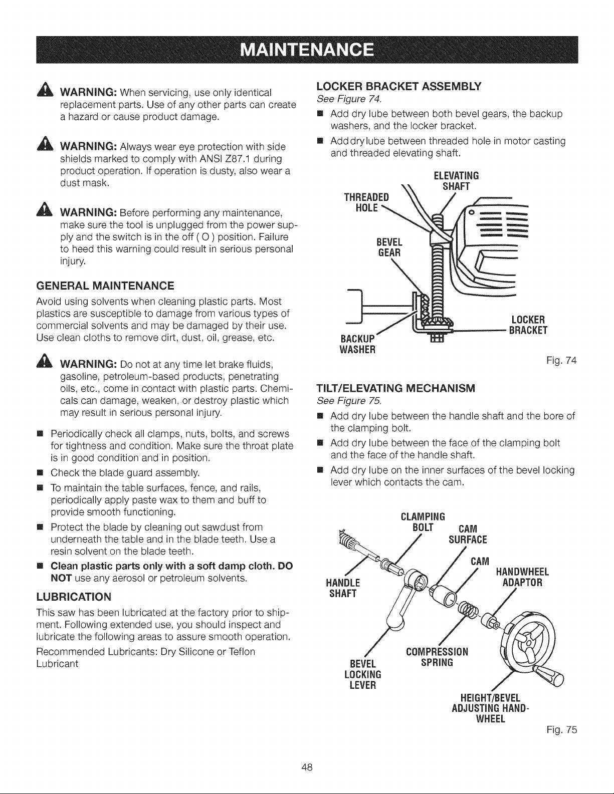
LOCKER BRACKET ASSEMBLY
See Figure 74.
[] Add dry lube between both bevel gears, the backup
washers, and the locker bracket.
[] Add drylube between threaded hole in motor casting
and threaded elevating shaft.
THREADED
HOLE
ELEVATING
SHAFT
BEVEL
GEAR
BACKUP
WASHER
LOCKER
BRACKET
Fig. 74
TILT/ELEVATING MECHANISM
See Figure 75,
[] Add dry lube between the handle shaft and the bore of
the clamping bolt.
[] Add dry lube between the face of the clamping bolt
and the face of the handle shaft.
[] Add dry lube on the inner surfaces of the bevel locking
lever which contacts the cam.
CLAMPING
• BOLT CAM
SURFACE
>j/0.o
/ __ / / HANDWHEEL
HANDLE _)._ ,,._./ ADAPTOR
BEVEL SPRING '_"_
LOCKING _"7"_
LEVER ,/
HEIGHT/BEVEL
ADJUSTING HAND-
WHEEL
Fig. 75
48
Loading ...
Loading ...
Loading ...