Loading ...
Loading ...
Loading ...
[] Positiontheworkpieceflatonthetablewiththeedge
flushagainsttheripfence.Letthebladebuildupto full
speedbeforefeedingtheworkpieceintotheblade.
[] Oncethebladehasmadecontactwiththeworkpiece,
usethehandclosestto theripfenceto guideit.
Makesuretheedgeoftheworkpieceremainsinsolid
contactwithboththeripfenceandthesurfaceofthe
table.If rippinganarrowpiece,usea pushstickand/
orpushblocksto movethepiecethroughthecutand
pasttheblade.
[] Whenthecutismade,turnthesawoff.Waitforthe
bladeto cometo acompletestopbeforeremovingthe
workpiece.
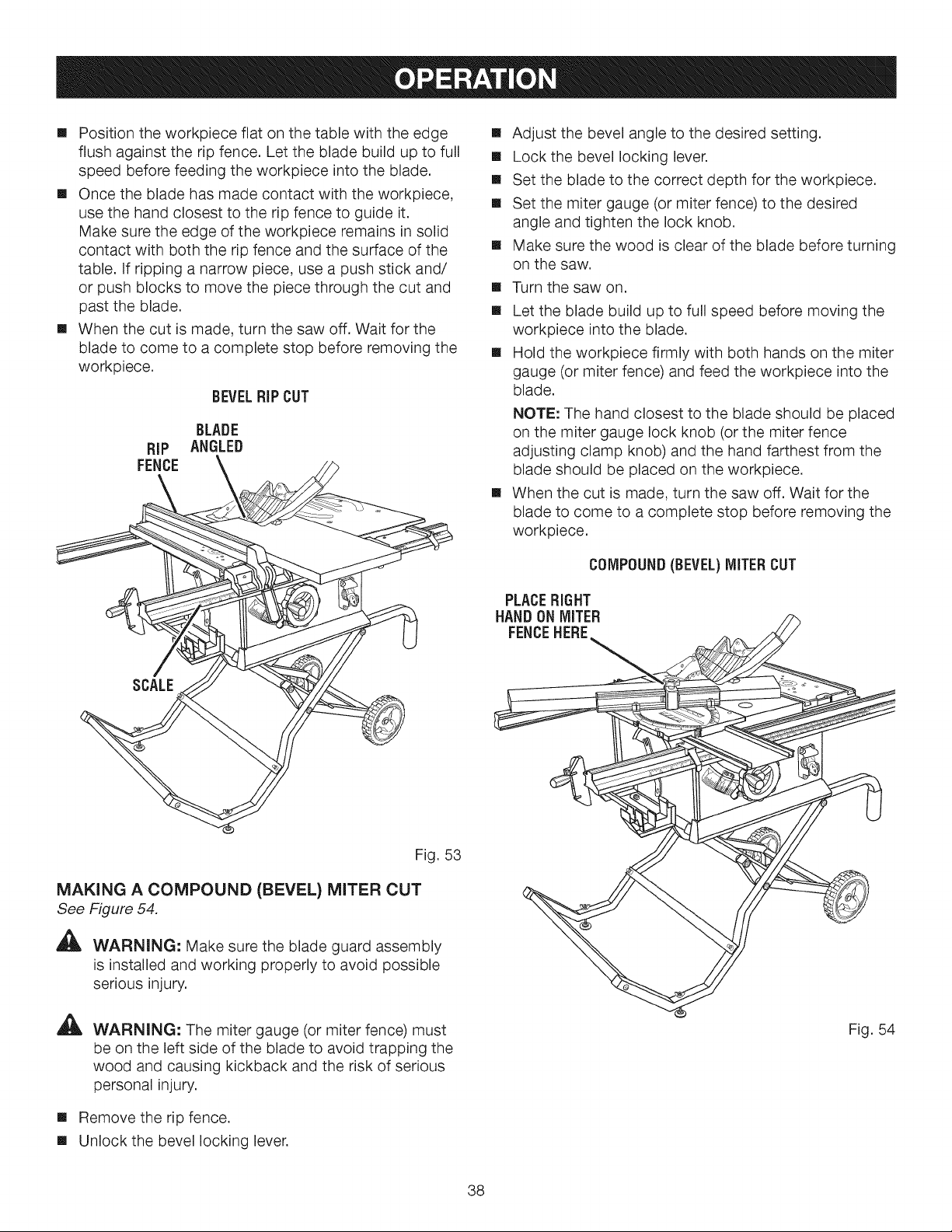
BEVELRiP CUT
BLADE
RiP ANGLED
FENCE
[] Adjust the bevel angle to the desired setting.
[] Lock the bevel locking lever.
[] Set the blade to the correct depth for the workpiece.
[] Set the miter gauge (or miter fence) to the desired
angle and tighten the lock knob.
[] Make sure the wood is clear of the blade before turning
on the saw.
[] Turn the saw on.
[]
[]
[]
Let the blade build up to full speed before moving the
workpiece into the blade.
Hold the workpiece firmly with both hands on the miter
gauge (or miter fence) and feed the workpiece into the
blade.
NOTE: The hand closest to the blade should be placed
on the miter gauge lock knob (or the miter fence
adjusting clamp knob) and the hand farthest from the
blade should be placed on the workpiece.
When the cut is made, turn the saw off. Wait for the
blade to come to a complete stop before removing the
workpiece.
COMPOUND(BEVEL)MITER CUT
PLACERIGHT
HANDON MITER
FENCEHERE
SCALE
Fig. 53
MAKING A COMPOUND (BEVEL) MITER CUT
See Figure 54.
A
WARNING: Make sure the blade guard assembly
is installed and working properly to avoid possible
serious injury.
A
WARNING: The miter gauge (or miter fence) must
be on the left side of the blade to avoid trapping the
wood and causing kickback and the risk of serious
personal injury.
[] Remove the rip fence.
[] Unlock the bevel locking lever.
Fig. 54
38
Loading ...
Loading ...
Loading ...