
Loading ...
Loading ...
Loading ...
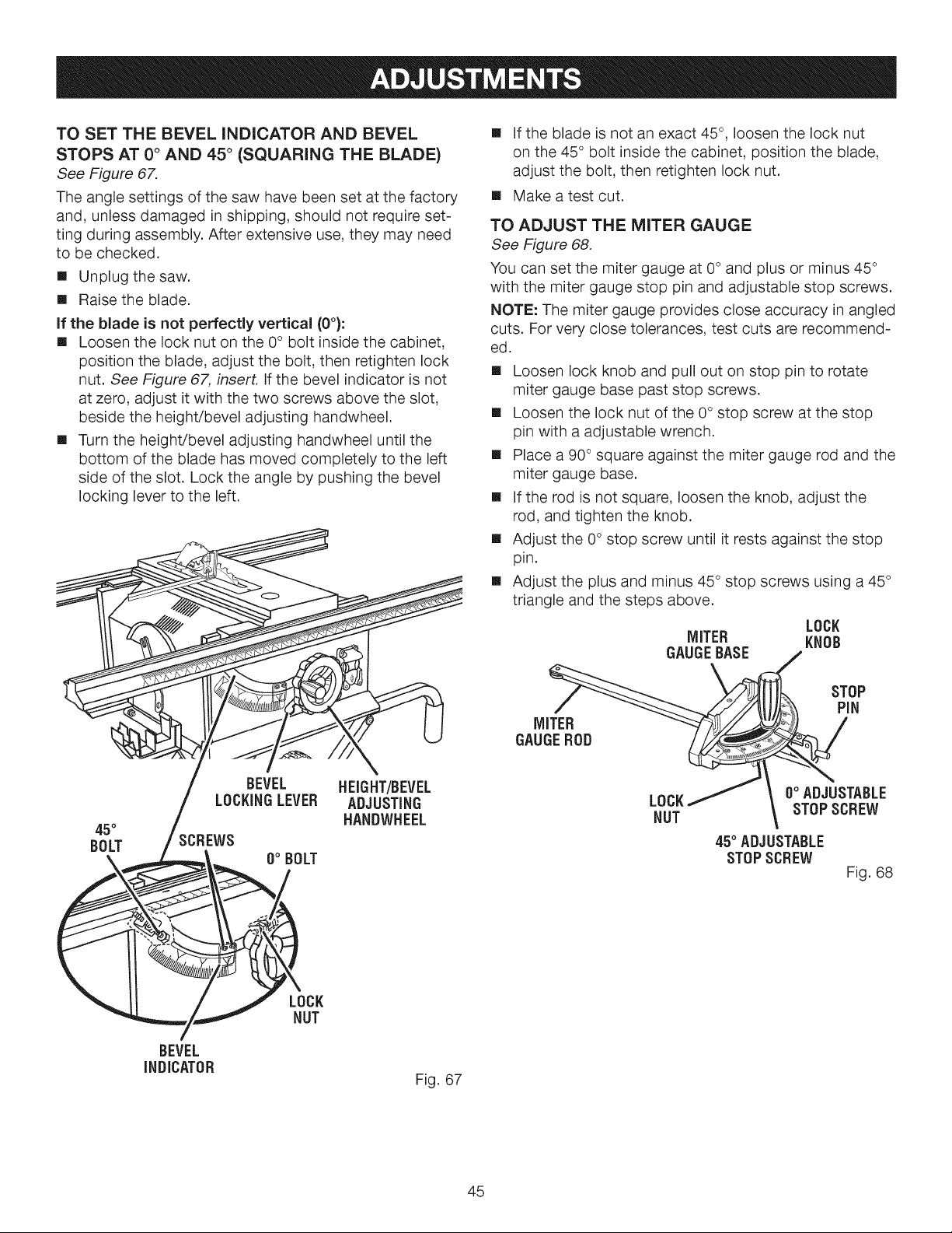
TO SET THE BEVEL INDICATOR AND BEVEL
STOPS AT 0 ° AND 45 ° (SQUARING THE BLADE)
See Figure 67.
The angle settings of the saw have been set at the factory
and, unless damaged in shipping, should not require set-
ting during assembly. After extensive use, they may need
to be checked.
[] Unplug the saw.
[] Raise the blade.
If the blade is not perfectly vertical (0°):
[] Loosen the lock nut on the 0 ° bolt inside the cabinet,
position the blade, adjust the bolt, then retighten lock
nut. See Figure 67, insert. If the bevel indicator is not
at zero, adjust it with the two screws above the slot,
beside the height/bevel adjusting handwheel.
[] Turn the height/bevel adjusting handwheel until the
bottom of the blade has moved completely to the left
side of the slot. Lock the angle by pushing the bevel
locking lever to the left.
45°
BOLT
BEVEL HEIGHT/BEVEL
LOCKINGLEVER ADJUSTING
HANDWHEEL
SCREWS
0° BOLT
BEVEL
INDICATOR
LOCK
NUT
Fig. 67
[] If the blade is not an exact 45 °, loosen the lock nut
on the 45 ° bolt inside the cabinet, position the blade,
adjust the bolt, then retighten lock nut.
[] Make a test cut.
TO ADJUST THE MITER GAUGE
See Figure 68.
You can set the miter gauge at 0 ° and plus or minus 45°
with the miter gauge stop pin and adjustable stop screws.
NOTE: The miter gauge provides close accuracy in angled
cuts. For very close tolerances, test cuts are recommend-
ed.
[] Loosen lock knob and pull out on stop pin to rotate
miter gauge base past stop screws.
[] Loosen the lock nut of the 0° stop screw at the stop
pin with a adjustable wrench.
[] Place a 90° square against the miter gauge rod and the
miter gauge base.
[] If the rod is not square, loosen the knob, adjust the
rod, and tighten the knob.
[] Adjust the 0° stop screw until it rests against the stop
pin.
[] Adjust the plus and minus 45° stop screws using a 45°
triangle and the steps above.
LOCK
MITER KNOB
GAUGEBASE
MITER
GAUGEROD
STOP
PIN
0° ADJUSTABLE
LOCK
NUT STOPSCREW
45° ADJUSTABLE
STOPSCREW
Fig. 68
45
Loading ...
Loading ...
Loading ...