Loading ...
Loading ...
Loading ...
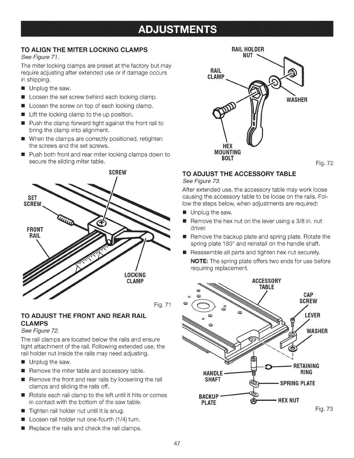
TO AL(GN THE MITER LOCKING CLAMPS
See Figure 71.
The miter locking clamps are preset at the factory but may
require adjusting after extended use or if damage occurs
in shipping.
[] Unplug the saw.
[] Loosen the set screw behind each locking clamp.
[] Loosen the screw on top of each locking clamp.
[] Lift the locking clamp to the up position.
[] Push the clamp forward tight against the front rail to
bring the clamp into alignment.
[] When the clamps are correctly positioned, retighten
the screws and the set screws.
[] Push both front and rear miter locking clamps down to
secure the sliding miter table.
SCREW
SET
SCREW
FRONT
RAIL
LOCKING
CLAMP
Fig. 71
TO ADJUST THE FRONT AND REAR RAIL
CLAMPS
See Figure 72.
The rail clamps are located below the rails and ensure
tight attachment of the rail. Following extended use, the
rail holder nut inside the rails may need adjusting.
[] Unplug the saw.
[] Remove the miter table and accessory table.
[] Remove the front and rear rails by loosening the rail
clamps and sliding the rails off.
[] Rotate each rail clamp to the left until it hits or comes
in contact with the bottom of the saw table.
[] Tighten rail holder nut until it is snug.
[] Loosen rail holder nut one-fourth (1/4) turn.
[] Replace the rails and check the rail clamps.
RAILHOLDER
NUT
RAiL
CLAMP
WASHER
HEX
MOUNTING
BOLT
Fig. 72
TO ADJUST THE ACCESSORY TABLE
See Figure 73.
After extended use, the accessory table may work loose
causing the accessory table to be loose on the rails. Fol-
low the steps below, when adjustments are required:
[] Unplug the saw.
[] Remove the hex nut on the lever using a 3/8 in. nut
driver.
[] Remove the backup plate and spring plate. Rotate the
spring plate 180 ° and reinstall on the handle shaft.
[] Reassemble all parts and tighten hex nut securely.
NOTE: The spring plate offers two ends for use before
requiring replacement.
ACCESSORY
TABLE
,_ _ CAP
Q _ SCREW
-. ft "/WASHER
NG
HANDLE -'-'--'-- [ RING
SHAFT _ )'_ SPRING PLATE
BACKUP
PLATE _ _ HEX NUT
Fig. 73
47
Loading ...
Loading ...
Loading ...