Loading ...
Loading ...
Loading ...
1-2
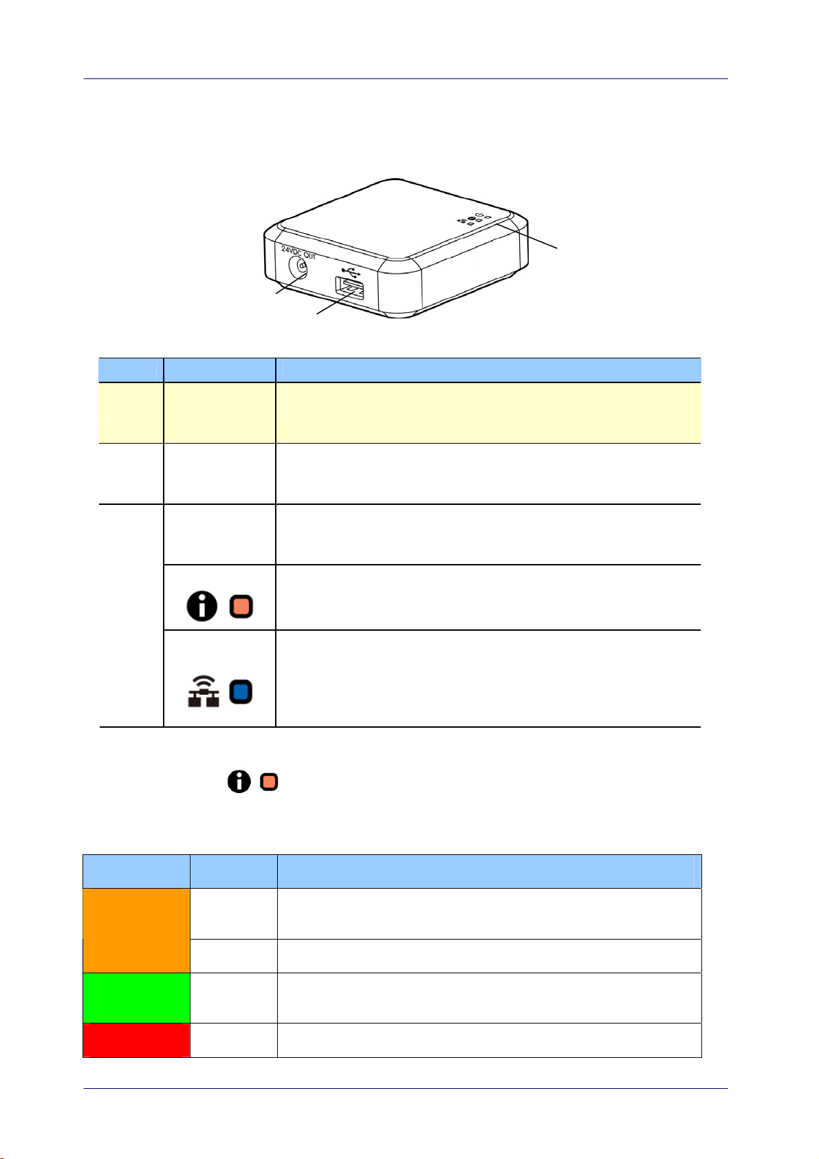
1.3 Ports and LED
Item Name Description
1
24VDC OUT
Port
Used to connect the power cable (included) to the
scanner.
2 USB Port
Used to connect the USB cable (included) to the scanner.
The USB port is used to transfer data only. It is not able to
supply power.
Power LED Turns green when the box is powered on.
Status LED
Indicates connection mode or operational status.
3
Wi-Fi/LAN
LED
Available only for the Wi-Fi version.
Status LED Light
The color and flashing frequency indicates the connection type and status.
LED Color Status Description
Solid Wired LAN mode with scanner connecting to the Network
Box
Orange
Blinking Ethernet cable disconnecting to the Network Box
Green Solid Wired LAN mode with scanner disconnecting to the
Network Box
Red Solid Firmware updating
Loading ...
Loading ...
Loading ...