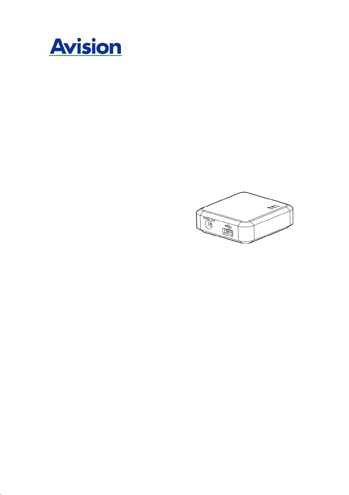
The Intelligent Network Box
User’s Guide
Regulatory model number: UNICORN
Avision Inc.
manual-en-250-0973-E-nbox-v200

Trademarks
Microsoft is a U.S. registered trademark of Microsoft Corporation.
Wi-Fi
®
is a registered trademark of the Wi-Fi Alliance.
Other brands and product names herein are trademarks or registered trademarks of their
respective holders.
Copyright
All rights reserved. No part of this publication may be reproduced, transmitted,
transcribed, stored in a retrieval system, or translated into any language or computer
language, in any form or by any means, electronic, mechanical, magnetic, optical,
chemical, manual, or otherwise, without the prior written permission of Avision Inc.
Material scanned by this product may be protected by governmental laws and other
regulations, such as copyright laws, the customer is solely responsible for complying
with all such laws and regulations.
Warranty
The information contained in this document is subject to change without notice.
Avision makes no warranty of any kind with regard to this material, including, but not
limited to, the implied warranties of fitness for a particular purpose.
Avision shall not be liable for errors contained herein or for incidental or consequential
damages in connection with the furnishing, performance, or use of this material.
Disposal of Waste Equipment by Users in Private Union
This symbol on the product or on its packaging indicates that the product can not be
disposed of with your other household waste. Instead it should be sent to appropriate
facilities for recovery and recycling in an effort to protect human health and the
environment. Fore more information about where you can drop off your waste
equipment for recycling, please contact your local city office, your household waste
disposal service or the shop where you purchased the product.
ii

User’s Guide
FCC Statement:
This equipment has been tested and found to comply with the limits for a Class B digital
device, pursuant to Part 15 of the FCC Rules. These limits are designed to provide
reasonable protection against harmful interference in a residential installation. This
equipment generates, uses and can radiate radio frequency energy and, if not installed
and used in accordance with the instructions, may cause harmful interference to radio
communications.
However, there is no guarantee that interference will not occur in a particular installation.
If this equipment does cause harmful interference to radio or television reception, which
can be determined by turning the equipment off and on, the user is encouraged to try to
correct the interference by one of the following measures:
Reorient or relocate the receiving antenna.
Increase the separation between the equipment and receiver.
Connect the equipment into an outlet on a circuit different from that to which the
receiver is connected.
Consult the dealer or an experienced radio/TV technician for help.
This device complies with Part 15 of the FCC Rules. Operation is subject to the following
two conditions: (1) This device may not cause harmful interference, and (2) this device
must accept any interference received, including interference that may cause undesired
operation.
IC Notice:
Operation is subject to the following two conditions:
1) This device may not cause interference and
2) This device must accept any interference, including interference that may cause
undesired operation of the device.
European Union Regulatory Notice
Products bearing the CE marking comply with the following EU Directives:
Low Voltage Directive 2006/95/EC
EMC Directive 2004/108/EC
Restriction of the use of certain hazardous substances (RoHS) Directive 2011/65/EU
This product satisfies the Class B limits of EN55022, EN55024, safety requirements of EN
60950 and ROHS requirements of EN50581.
iii

Product Safety Guide
Please clearly read all these instructions, and follow all instructions and warnings before
installing and using the device.
The following indications are used in this document to obviate any chance of accident or
damage to you and/or the device.
WARNING Indicates potentially hazardous situations, which if instructions
are not followed, could result in death or serious injury.
CAUTION Indicates a potentially hazardous situation which, if instructions
are not followed, may result in minor or moderate injury or
damage to property.
WARNING
Use only the USB cable that came with your device and avoid abrasions, cuts,
fraying, crimping, and kinking. Using any other USB cable could cause fire, electrical
shock, or injury.
Place the device close enough to the computer so that the interface cable can easily
reach between the device and the computer.
Do not place or store the device:
Outdoors
Near excessive dirt or dust, water, or heat sources
In locations subject to shocks, vibrations, high temperature or humidity, direct
sunlight, strong light sources, or rapid changes in temperature or humidity
Do not use the device with wet hands.
Never disassemble, modify, or attempt to repair the device or device option by
yourself, except as specifically explained in the device's documentation. This could
cause fire, electrical shock, or injury.
Unplug the device and the USB cable, and refer servicing to qualified service
personnel under the following conditions:
Liquid has entered the device.
Object has entered the device.
The device has been dropped, or the case has been damaged.
The device does not operate normally (i.e. appearance of smoke, strange smell,
odd noise, etc.), or exhibits a distinct change in performance.
Unplug the device and the USB cable before cleaning.
iv

User’s Guide
CAUTION:
Do not locate the device on rackety or aslope tables. Do not locate the device on
unstable surface. The device may fall down and this may result in injury.
Do not place heavy objects on the unit. It may cause unbalance and the device may
fall down. This may result in injury.
Store the AC Power cord/USB cable bundled out of the reach of children to avoid the
risk of injury.
Keep plastic bags bundled out of the reach of children to avoid the danger of
suffocation.
If you are not going to use the device for a long period, unplug the USB cable from
the electrical outlet.
v

vi
Table of Contents
1. Overview ........................................................................... 1-1
1.1 Introduction.................................................................................... 1-1
1.2 Package Contents............................................................................ 1-1
1.3 Ports and LED ................................................................................. 1-2
2. Installation........................................................................ 2-1
2.1 Precautions..................................................................................... 2-1
2.2 Connect Network Box to the Scanner.................................................. 2-1
2.3 Connect Network Box to Power.......................................................... 2-2
2.4 Connect to the Ethernet Cables.......................................................... 2-3
3. Operation........................................................................... 3-1
3.1 Scan From A Wired Computer............................................................ 3-1
4. Use the Embedded Web Page ............................................ 4-1
4.1 View Network Box’s Web Page........................................................... 4-1
4.2 The Status Page .............................................................................. 4-2
4.3 The System Page............................................................................. 4-3
4.4 The Network Page............................................................................ 4-4
5. Troubleshooting................................................................. 5-1
5.1 Q&A............................................................................................... 5-1
5.2 Technical Service............................................................................. 5-2
User’s Guide
1. Overview
1.1 Introduction
By connecting the Network Box to your scanner, your scanner* can be converted into a
network device to let other computers scan a document and receive a scanned image in
the LAN.
* Only available for selected Avision scanner models. Check with Avision’s web site
(www.avision.com) for complete supported models.
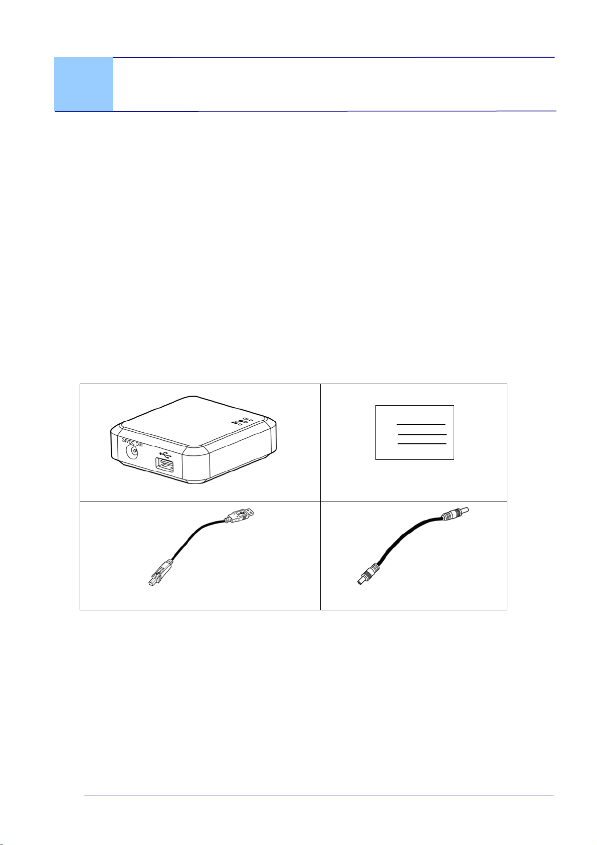
1.2 Package Contents
Standard package items for Network Box:
Main unit
Quick Guide
USB Cable
Power Cable
* To ensure quality support and service, please register the product from Avision’s web
site at www.avision.com. *
1-1
1-2
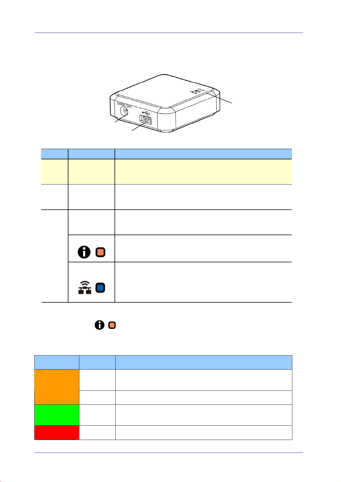
1.3 Ports and LED
Item Name Description
1
24VDC OUT
Port
Used to connect the power cable (included) to the
scanner.
2 USB Port
Used to connect the USB cable (included) to the scanner.
The USB port is used to transfer data only. It is not able to
supply power.
Power LED Turns green when the box is powered on.
Status LED
Indicates connection mode or operational status.
3
Wi-Fi/LAN
LED
Available only for the Wi-Fi version.
Status LED Light
The color and flashing frequency indicates the connection type and status.
LED Color Status Description
Solid Wired LAN mode with scanner connecting to the Network
Box
Orange
Blinking Ethernet cable disconnecting to the Network Box
Green Solid Wired LAN mode with scanner disconnecting to the
Network Box
Red Solid Firmware updating
User’s Guide
1-3
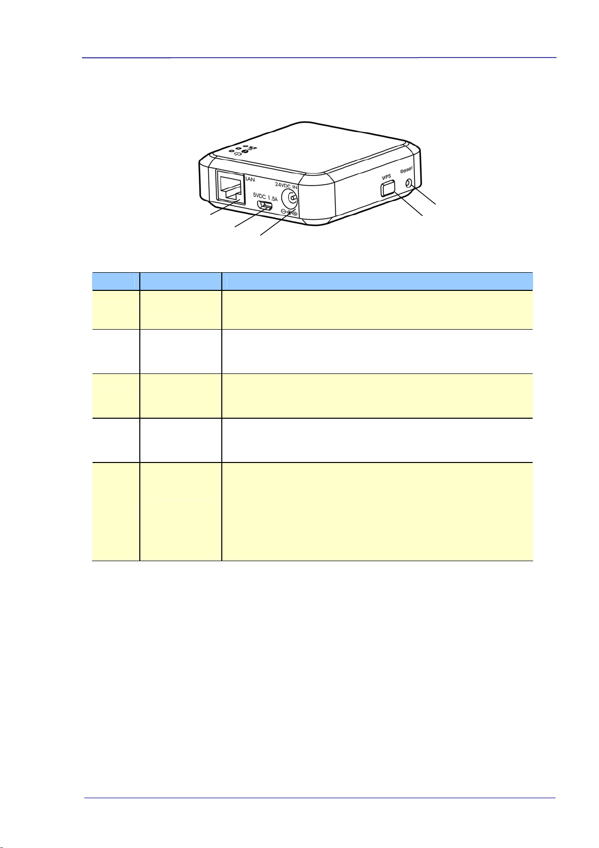
Item Name Description
4
LAN Port
Used to connect the LAN cable to the Network Box for
wired network connection.
5
5VDC 1.5A
Port
For scanner without a 24VDC power jack, use this port to
connect the box to a USB power adapter via a Micro USB
cable.
6
24VDC IN
Port
Used to connect the power adapter that comes with the
scanner to the Network Box.
7 WPS Button Available only for the Wi-Fi version.
8
Reset
Button
Restore to factory default settings. To reset the Network
Box, use a pen to press and hold this button for about 5
seconds. Release the button and then the orange LED
turns off. Wait for at least 60 seconds until the orange
LED starts blinking (without connecting the ethernet cable)
or turns solidly on (with ethernet cable connecting to
Network Box).
User’s Guide
2. Installation
2.1 Precautions
Keep the product out of direct sunlight. Direct exposure to the sun or
excessive heat may cause damage to the unit.
Do not install the product in a humid or dusty place.
Place the product securely on an even, flat surface. Tilted or uneven surfaces
may cause mechanical or paper-feeding problems.
Retain the product box and packing materials for shipping purposes.
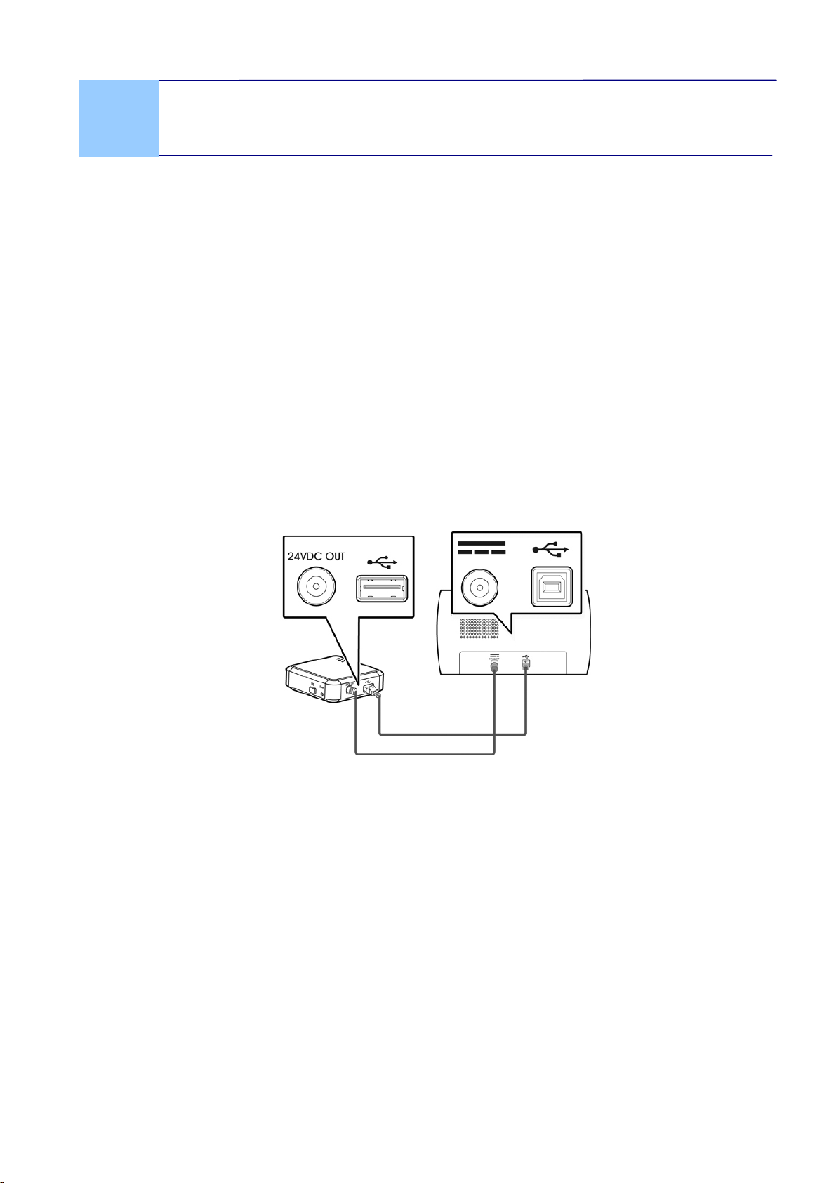
2.2 Connect Network Box to the Scanner
b
a
a: The supplied power cable
b: The supplied USB cable
1. Plug one end of the supplied power cable (a) to the power jack of the scanner
and the other end to the port marked “24VDC OUT” of the Network Box.
2. Connect the square end of the supplied USB cable (b) to the USB port of the
scanner and the rectangle end to the USB port of the Network Box.
2-1
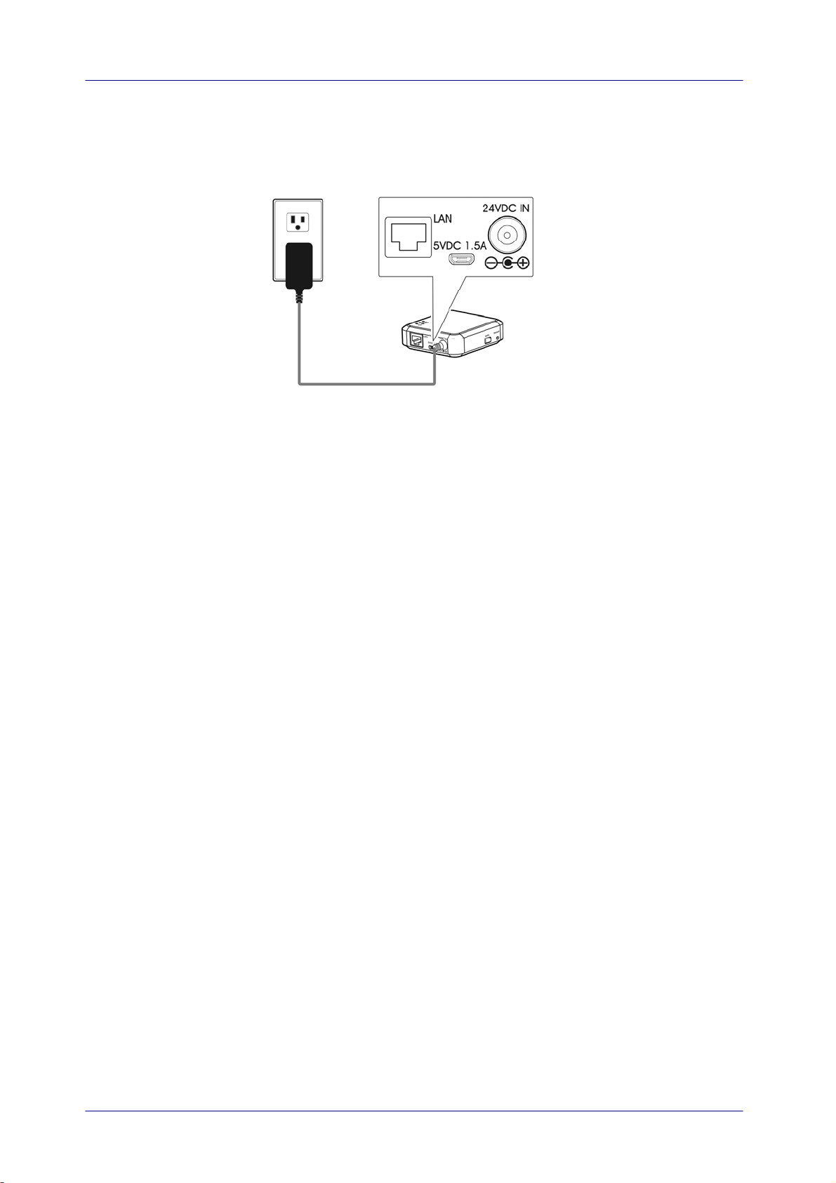
2.3 Connect Network Box to Power
c
c: The power adapter that comes with the scanner
Connect the small end of the power cable (c) that comes with the scanner to the
port marked “24VDC IN” of the Network Box and the other end to a power
outlet.
2-2
User’s Guide
2-3
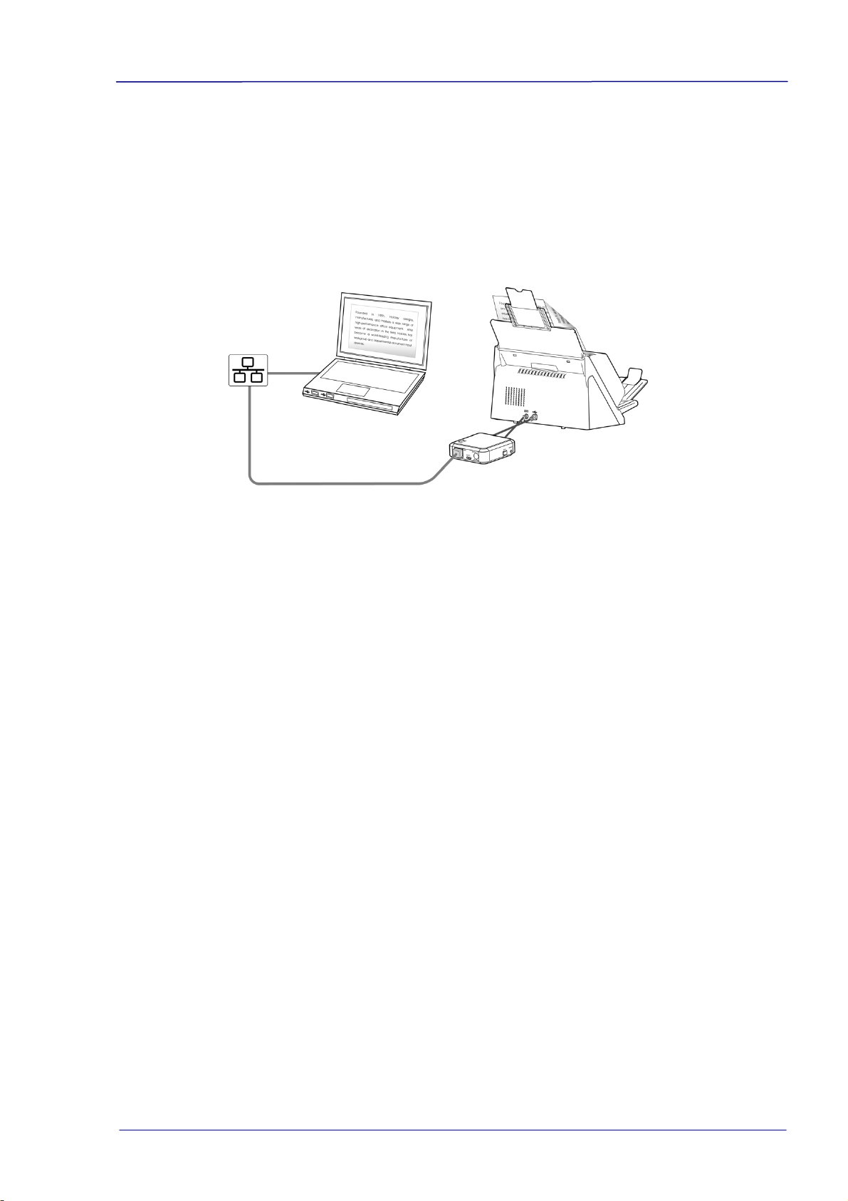
2.4 Connect to the Ethernet Cables
In wired network mode, your computer is connected to Network Box through Ethernet
cables.
d
e
d/e: E
thernet LAN cable
1. Plug one end of the network cable (d) to the available port of the switching hub of
your LAN. Plug the other end to the LAN port of your computer.
2. Plug one end of the network cable (e) to the available port of a switching hub of
your LAN. Plug the other end to the LAN port of the Network Box.
User’s Guide
3. Operation
Before You Begin!
Make sure the LAN cables have been connected properly on your switching hub
FIRST and then connect the power of the Network Box. Otherwise, other
computers in the network may obtain IP address from the box and therefore may
not connect to the internet.
3.1 Scan From A Wired Computer
Before operating the network scanner, to install the latest scanner driver is not required.
Instead, it is necessary to download and install the useful network tool – [Virtual
Scanner Link] from Avision’s web site on http://www.avision.com to help you search
and connect the scanner i
n the network.
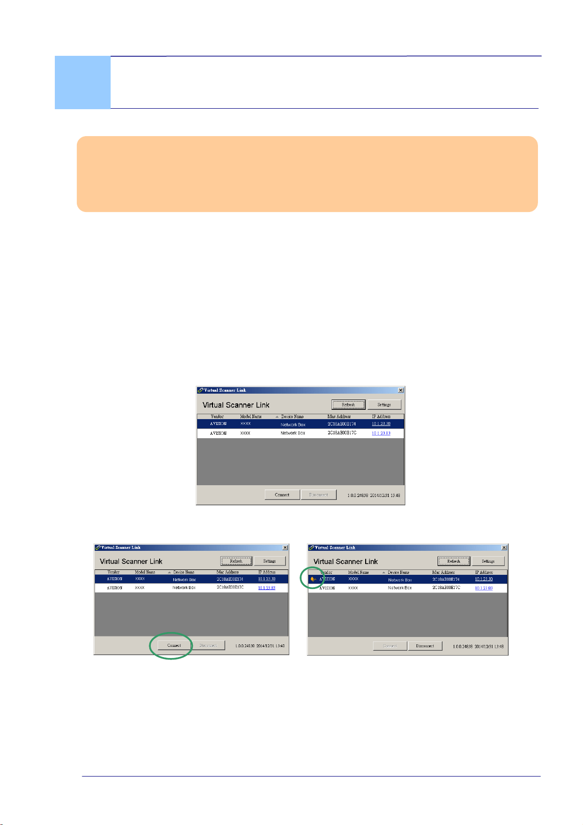
1. Start [Virtual Scanner Link] by choosing Start>All Programs>Avision Virtual
Scanner>Virtual Scanner Link. The main window will be displayed and the
scanners in your network will be searched automatically. In a few seconds, the result
including the scanner model and Network Box’s IP address will be displayed as
shown.
2. Choose the scanner you wish to connect and then press [Connect]. If connection is
successful, a connection mark will be displayed as shown.
3-1
Note:
The network scanner can be used by one user at a time. If the network scanner
is being used by other user, you will be prompted with a message to connect the
scanner later. When the scanner is available, you will also be prompted with a
message to connect the scanner and start scanning your document.
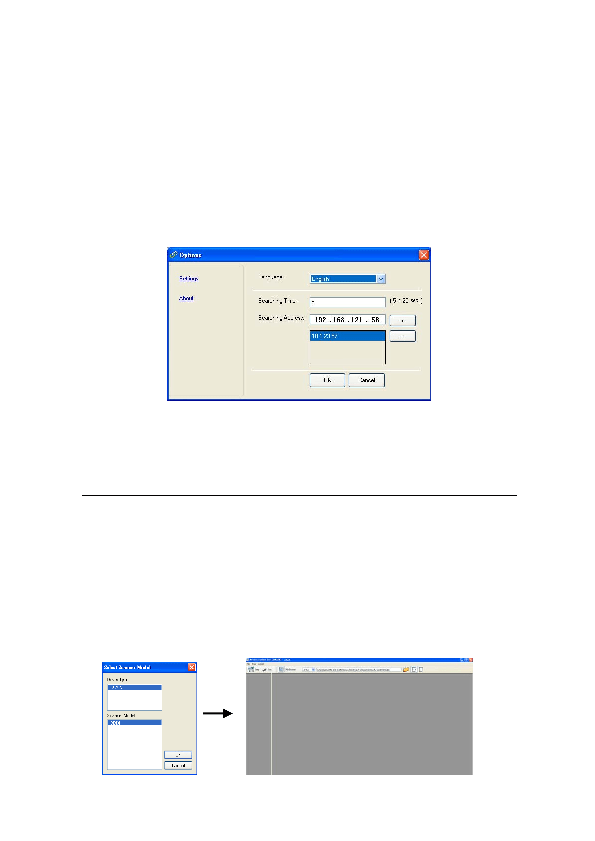
If the network scanner has not been found, it is probably the scanner and your
computer are not in the same sub network (LAN). In this case, you can assign a
specific IP address of the scanner to let [Virtual Scanner Link] automatically
search the scanner. Click the [Option] button, type your IP address on the
[Searching Address] field (1), then click the [+] button (2) and finally click
[OK] (3) to complete.
(1)
(2)
(3)
Searching Time: When the program is launched, it automatically searches the
scanner in the network in 5 seconds (default). The searching time can be
changed from a range of 5 to 20 seconds.
If the [Virtual Scanner Link] program has been closed and then launched
again, [Virtual Scanner Link] will automatically search and connect the
network scanner it has previously connected to.
3. After the scanner has been connected successfully, launch your TWAIN-compliant
image-editing software application such as Avision Capture Tool by choosing
Start>All Programs>Avision xxx Scanner>Avision Capture Tool (xxx indicates
your scanner model).
4. A [Select Scanner Model] dialog box appears. Choose your scanner model and
click [OK].
If more than one scanner on the network, a [Network Scanner] dialog will be
prompted. Choose your desired scanner with correct MAC address and click [OK].
5. The main window of Avision Capture Tool appears. Press [Scan] to start scanning.
In a second, the scanned image will be displayed.
3-2

User’s Guide
3-3
Important:
Wh
en using the bundled software Avision Capture Tool to scan, you may be prompted
with the message “Can not find scanner”. Please wait a while and try again as the
scanner may be warming up or communicating with Network Box.
User’s Guide
4. Use the Embedded Web Page
The embedded web page of Network Box allows you to display basic information, change
your connection type and other settings.
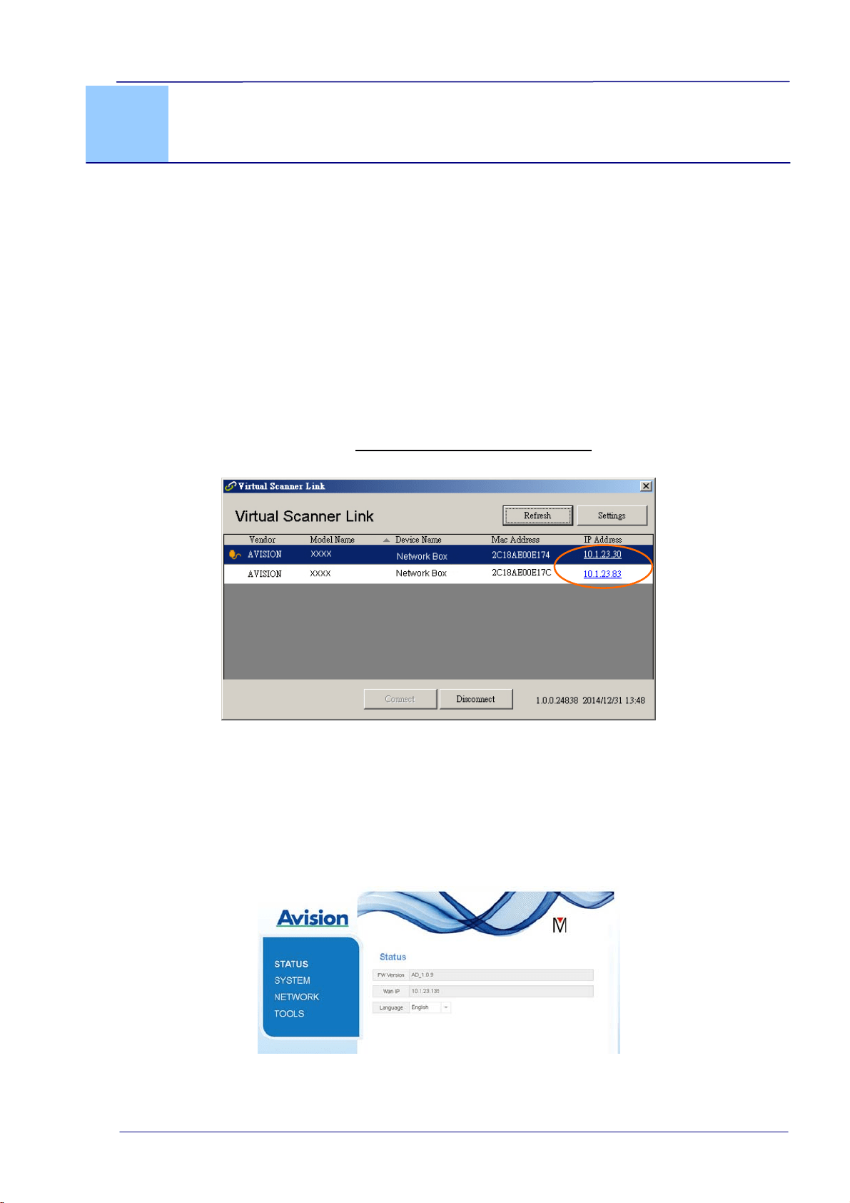
4.1 View Network Box’s Web Page
1. Open your browser.
2. Type the IP address of the connected Network Box on the URL address. For example,
http://10.2.23.30
The IP address can be obtained from the window of [Virtual Scanner Link]. (Refer
to the preceding section 3.1 Scan From A Wired Computer
to use the [Virtual
Scanner Link].)
Alternatively,
You may simply click the IP Address on the window of the Virtual Scanner Link.
3. Enter admin as your login name and password, then the web page of Network Box
will be displayed. (If required, you may change the user name and the password
later on the [Network] page.)
4-1
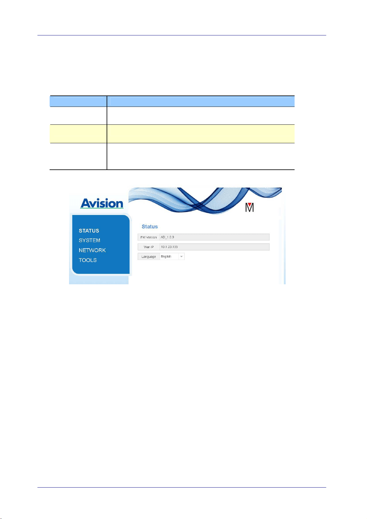
4.2 The Status Page
The [Status] page includes the following information:
Name Description
FW Version Displays current firmware version.
WAN IP Displays IP address.
Language Displays current language for the web page.
Choice: English, Chinese
4-2
User’s Guide
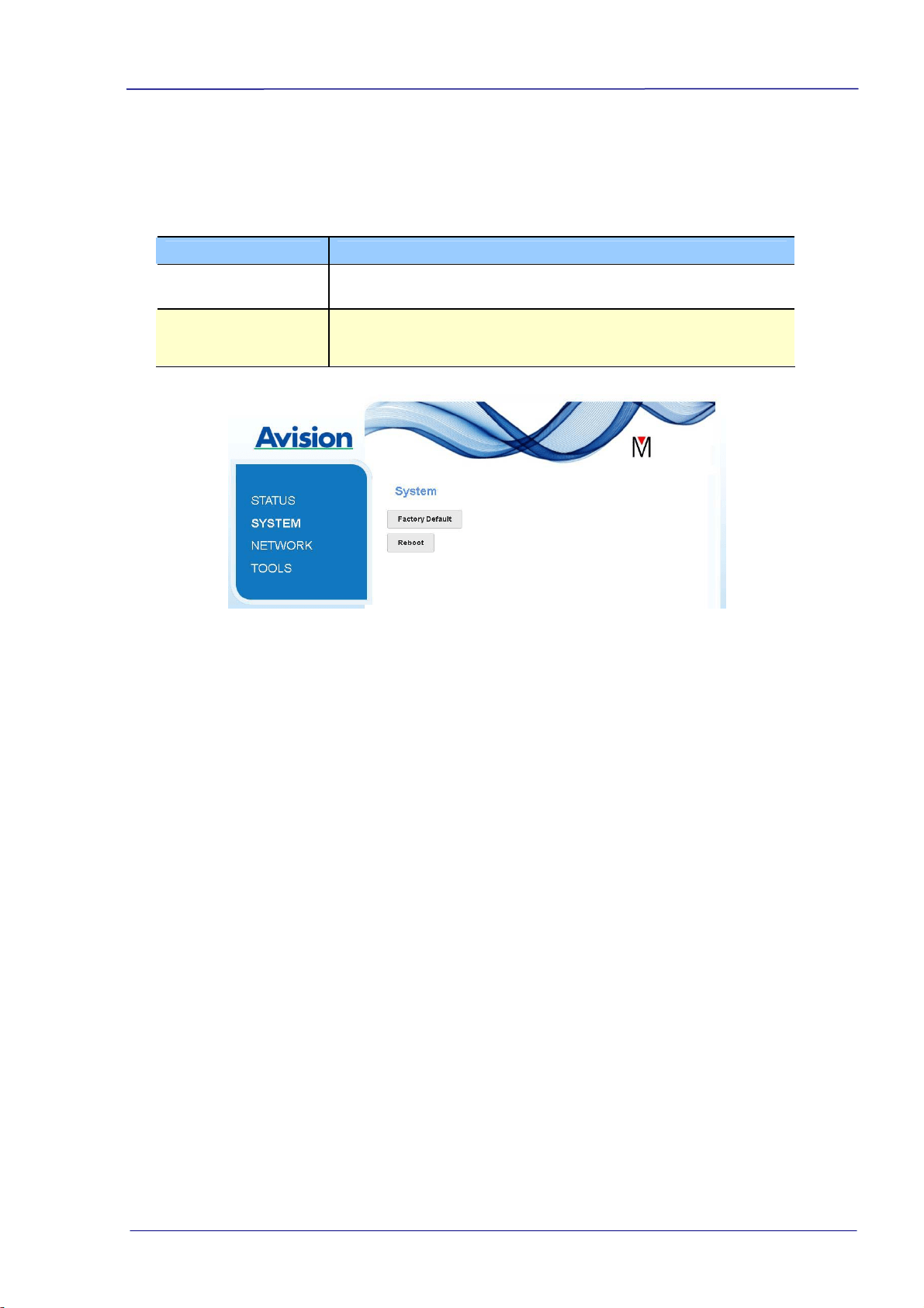
4.3 The System Page
The [System] page includes the following options:
Name Description
Factory Default Restore settings to factory default.
Reboot Restart Network Box. The orange LED light turns off first
then blinking and finally solidly on.
To restore settings to factory default,
1. Press the [Factory Default] button. A [Confirmation] dialog box appears.
2. Press [Yes] to complete the settings.
3. The orange LED light turns off.
4. Wait for about 60 seconds until the orange LED light turns solidly on.
Alternatively,
You may press the [Reset] button on Network Box to restore settings to default.
1. Use your pen to press and hold the [Reset] button for about 5 seconds. Release the
button and then the orange LED light turns off.
2. Wait for about 60 seconds until the orange LED light turns solidly on.
4-3
4-4
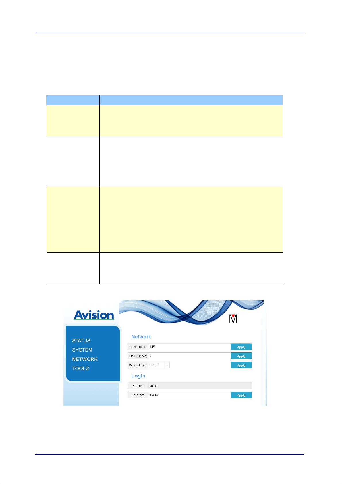
4.4 The Network Page
The [Network] page includes the following options:
Name Description
Device Name Displays current network name for Network Box.
You may type your desired name on the field and then click
[Apply] to complete.
Timeout Timeout for the connected network scanner: The allowable
connection time after your last action. Range: 10 ~ 3,600
seconds. (Default is 0). If 0 second is set, this means no
restriction on the connection time. If 300 seconds (5
minutes) is set, this means the network scanner will be
disconnected 5 minutes after your last action.
Connection
Type
Choice: DHCP (default), Static
DHCP: Choose DHCP to obtain IP/subnet/gateway
addresses automatically provided by the DHCP server.
Static: Choose Static to assign your designated IP address.
Type IP address on the following fields such as IP address,
Subnet Mask, Gateway IP, Primary DNS, and Secondly DNS.
DNS: Domain Name Server
Login Displays current login user name for the web page.
You may type your desired password on the password field
and then click [Apply] to complete.

User’s Guide
5. Troubleshooting
5.1 Q&A
How to update the latest firmware of Network Box?
To download the latest firmware,
1. Obtain and download the latest firmware to your USB flash drive from Avision’s web
site at http://www.avision.com.
2. Disconnect the USB cable connecting Network Box and the scanner.
3. Pl
ug your USB flash drive containing the latest firmware file to the USB flash drive of
Network Box.
4. Connect the power cord to the port marked “24VDC IN”.
5. The LED light turns solidly on in red color when the firmware is updating.
6. After about 3 minutes when the firmware has been successfully updated, the red
LED light will be off and the status LED light resumes to its original status.
5-1

5-2
5.2 Technical Service
Before contact Avision, please prepare the following information:
Scanner serial & revision number (located on the bottom of the scanner);
Hardware configuration (e.g., your host CPU type, RAM size, free disk space, display
card, interface card);
Headquarter
Avision Inc.
No. 20, Creation Road I, Science-Based Industrial Park,
Hsinchu 300, Taiwan, ROC
TEL: +886 (3) 578-2388
Toll Free: 0800-600-785
FAX: +886 (3) 577-7017
E-MAIL: [email protected]
Web Si
te: http://www.avision.com.tw
US and Canada Area
Avision Labs, Inc.
6815 Mowry Ave., Newark CA 94560, USA
TEL: +1 (510) 739-2369
Toll Free: 1-888-909-7888
FAX: +1 (510) 739-6060
E-MAIL: [email protected]
Web Site: http://www.avision.com
China Area
Avision(Suzhou) Co., Ltd.
No.9, Suhong West Road, Suzhou Industrial Park,
Jiangsu Province, PRC 215021
TEL:+86-512-62565888
Toll Free:+86-400-185-8566
FAX:+86-512-62560115
E-MAIL:[email protected]
Web Site:http://www.avision.com
Europe Area
Avision Europe GmbH
Bischofstr. 101 D-47809 Krefeld Germany
TEL: +49-2151-56981-40
FAX: +49-2151-56981-42
E-MAIL: [email protected]
Web Site: http://www.avision.de