Loading ...
Loading ...
Loading ...
I
I
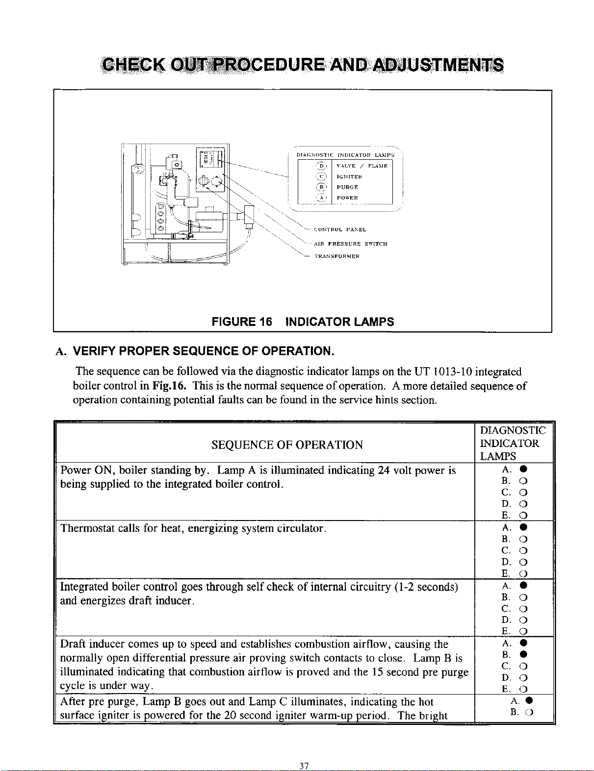
FIGURE 16 INDICATOR LAMPS
A. VERIFY PROPER SEQUENCE OF OPERATION.
The sequence can be followed via the diagnostic indicator lamps on the UT 1013-10 integrated
boiler control in Fig.16. This is the normal sequence of operation. A more detailed sequence of
operation containing potential faults can be found in the service hints section.
DIAGNOSTIC
SEQUENCE OF OPERATION INDICATOR
LAMPS
Power ON, boiler standing by. Lamp A is illuminated indicating 24 volt power is A. •
being supplied to the integrated boiler control. B. O
C. O
D. O
E. O
Thermostat calls for heat, energizing system circulator. A. •
B. 0
C. 0
D. 0
E. 0
Integrated boiler control goes through self check of internal circuitry (1-2 seconds) A. •
and energizes draft inducer. B. O
C. O
D. O
E. O
Draft inducer comes up to speed and establishes combustion airflow, causing the A. •
normally open differential pressure air proving switch contacts to close. Lamp B is B. •
C. O
illuminated indicating that combustion airflow is proved and the 15 second pre purge D. O
cycle is under way. E. O
After pre purge, Lamp B goes out and Lamp C illuminates, indicating the hot A. •
surface igniter is powered for the 20 second igniter warm-up period. The bright B. O
37
Loading ...
Loading ...
Loading ...