
GE Monogram
®
36" Bottom Mount
Refrigerators
Custom
Options Guide
and
Installation
Instructions
With Custom Panel Dimensions
and Trim Kit Installation Instructions
Models:
ZIC36N RH
ZIC36N LH
These Monogram refrigerators are
designed to be customized with decorator
door and grille panels. Field installed
panels are required.
Factory installed trim will accommodate
1/4" thick custom panels or optional
Lexan
®
and stainless steel panel kits.
Optional trim kits allow an even broader
range of custom appearance options.
Read this booklet carefully to accomplish the
desired appearance and to insure a trouble free
installation.
This booklet contains information and
illustrations to demonstrate custom
possibilities. Custom door and grille panel
sizes vary to accommodate the kit being
used. Dimensions for each application are
included and can be faxed or sent to the
cabinet manufacturer so that the panels can
be constructed accurately.

Before you begin - Read these instructions completely and carefully.
IMPORTANT - Save these instructions for local inspector’s use.
IMPORTANT - OBSERVE ALL GOVERNING CODES AND ORDINANCES.
Note to Installer - Be sure to leave these instructions with the Consumer.
Note to Consumer - Keep these instructions with your Use and Care Book for future reference.
This appliance must be properly grounded. See “Grounding the Refrigerator,” page 12.
Monogram
36" Bottom Mount Refrigerator
2
Contents
Design Information
Flush or Semi-Flush Enclosure Installations ............................................................................................................................... 3
Enclosure Cutout and Product Dimensions................................................................................................................................. 3
Installation Examples, Between Base & Wall Cabinets ........................................................................................................... 4
Installation at End-of-Run ............................................................................................................................................................... 4
Frameless Cabinets .......................................................................................................................................................................... 4
Accessory Panel Kits ....................................................................................................................................................................... 4
Models Available .............................................................................................................................................................................. 5
Advance Planning Exterior Appearance Options....................................................................................................................... 5
Trim Kit Descriptions ........................................................................................................................................................................ 6
Custom Panel Dimensions
Product and Cutout Information .................................................................................................................................................... 7
1/4" Thick Custom Panels or Panels Secured to 1/4" thick backing........................................................................................ 8
3/4" Thick Panels with Supplied Handle, ZKTC36L or ZKTC36R............................................................................................... 9
3/4" Thick Panels with Custom Handle ....................................................................................................................................... 10
Side Panel or Filler Options .......................................................................................................................................................... 11
Installation Instructions...........................................................................................................................................................12-17
Trim Kits
ZGC2 Trim Kit, Grille Panel Frame Adjustment .......................................................................................................................... 18
ZKHC1 Trim Kit (for 1/4" Panels), Support for Custom Handles.........................................................................................19-21
ZKTC36L/ZKTC36R Trim Kit, 3/4" Custom Panels ..................................................................................................................22-27
ZKHTC1 Trim Kit (for 3/4" Panels), Support for Custom Handles ......................................................................................28-31
ZKHCSS1 Trim Kit (for 1/4" Panels), Tubular Stainless Steel Handles .............................................................................32-35
ZKHTCSS1 Trim Kit (for 3/4" Panels), Tubular Stainless Steel Handles...........................................................................36-38
ZFC1 Trim Kit, for side to side installation .................................................................................................................................. 39
If you have a question concerning the installation of this
product, call the GE Answer Center
®
Consumer
Information Service at 800.626.2000, 24 hours a day,
7 days a week.
If you received a damaged refrigerator, you should
immediately contact your dealer or builder.
Proper installation is the responsibility of the installer.
Product failure due to improper installation is not
covered under the GE Appliance Warranty. See the
Use & Care Guide for warranty information.
WARNINGS:
• Use this appliance only for its intended purpose.
• Immediately repair or replace electric service cords
that become frayed or damaged.
• Unplug the refrigerator before cleaning or making
repairs.
• Repairs should be made by a qualified service
technician.
For Monogram local service in your area,
1-800-444-1845.
For Monogram service in Canada
1-888-880-3030
For Monogram Parts and Accessories, call
1-800-626-2002.
3
Design Information
36" Bottom Mount Refrigerators
Flush or
Semi-Flush
Enclosure
Installations
Side Panels Requirements:
• Side panels are not required whenever the
refrigerator is installed into an enclosure or between
pantry and oven cabinets.
• Side panels are required whenever the sides of the
refrigerator are exposed.
• Side panel sizes vary depending on the type of
installation being made.
To accomplish an attractive installation, you must:
1. Determine the need for side panels.
2. Determine side panel thickness.
3. Order matching side panels from the cabinet
manufacturer. Be sure to provide the exact dimen-
sions.
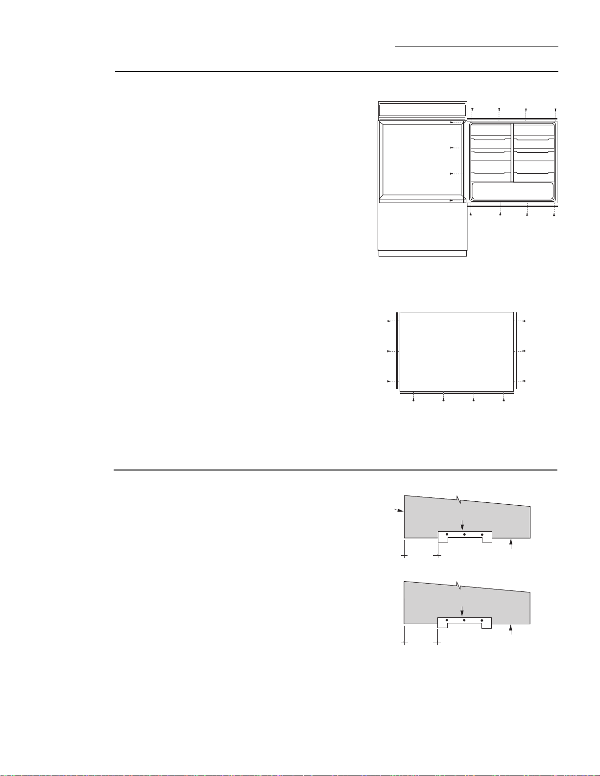
True Flush Installation
In a flush installation,
the refrigerator doors
will align evenly with the
front face of adjacent cabinet
doors. The refrigerator blends
into the surrounding cabinetry.
Semi-Flush Installation
These refrigerators
can also be installed
semi-flush into an enclosure
using the minimum cutout
width. The case trim creates a
frame around the opening.
Monogram built-in refrigerators can be installed flush
with typical 24-3/4" deep cabinetry.
When installed semi-flush, the case trim will conceal
slight gaps around the enclosure. The refrigerator will
project forward approximately 3/4" beyond the front
face of surrounding cabinetry.
In any installation situation, a wide range of appear-
ance options can be accomplished through the use of
one or more trim kits. See trim kit descriptions and
appearance options on page 6.
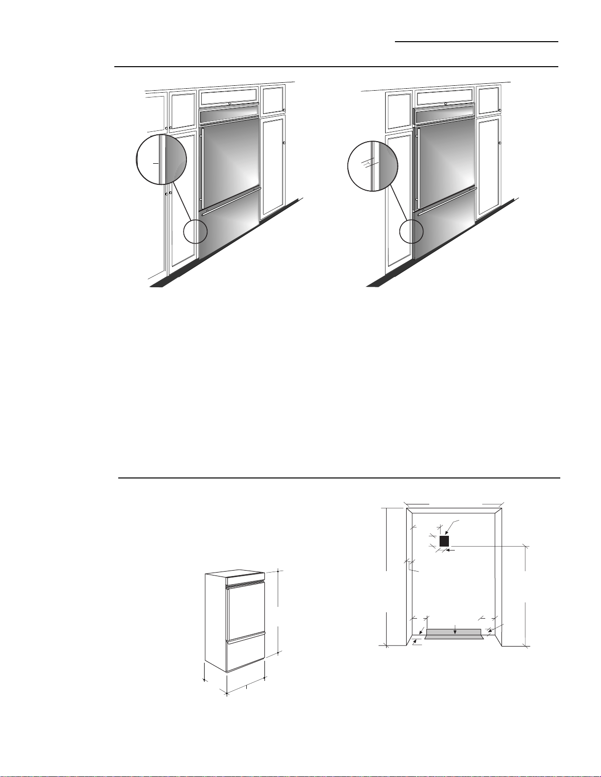
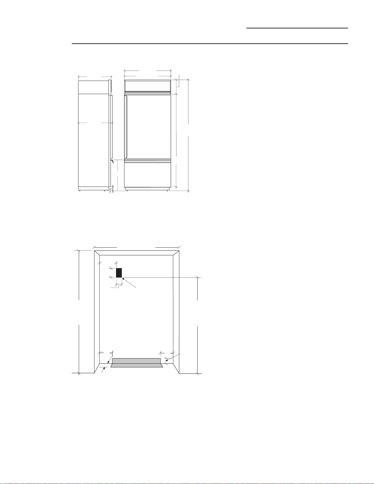
Enclosure
Cutout and
Product
Dimensions
• To achieve a flush fit the finished cutout width must
be at least 36" wide.
• A semi-flush installation requires 35-1/2" min. finished
cutout width.
• The electrical and water locations must be located as
shown for either type of installation.
*36" Min. for a flush installation
35-1/2" Min. for a semi-flush installation
Note: Additional cutout width may be required when
side panels are used. Add side panel thickness to the
finished cutout to calculate rough-in width. See
installation examples on the following page.
Advance Planning
0"
3/4"
36"
83-1/2" Min
84-1/2" Max
24-3/4"
7"
Wall View
Electrical
Area
84 1/2" max
83 1/2" min
Finished
Opening
74" From Floor
to
Bottom
of Electrical
5"
5"
3 1/2"
5"
3 1/2"
Water Supply
24 3/4" Total
Depth
*Finished Width
7 1/2"
4
Design Information
36" Bottom Mount Refrigerators
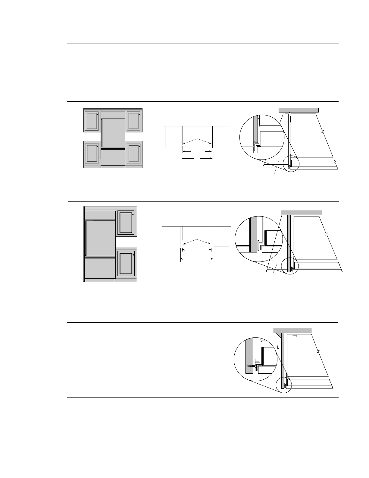
Installation
At End-of-Run
Frameless
Cabinets
Note: 1/2" thick side panels shown. Side panels can
be any thickness. Add side panel thickness to outside
trim width (36”) to calculate the rough-in dimension.
The leading (front) edge must be finished to match
surrounding cabinetry.
Side panels, 1/2" minimum thickness are required when
using frameless cabinets. The side panel acts as a
spacer between the cabinet and the case trim and
prevents interference with cabinet door swing. The
leading (front) edge must be finished to match
surrounding cabinetry.
1/2" To 3/4" Side Panels. Leading
Edge Flush With Cabinet
1/2" To 3/4" Side Panels. Leading
Edge Flush With Cabinet
Side panels are required whenever the sides of the refrigera-
tor will be exposed.
1/2" to 3/4" side panels are normally set into place and
fastened to adjacent cabinetry or to the back wall before
rolling the refrigerator into the opening.
Installation
Between
Base &
Wall Cabinets
Note: 1/4" thick side panels can be
inserted into the case trim, making the
rough-in the same as the outside trim
width, 36”.
1/4" Side Panels. Insert end of
side panel into trim
Installation Examples
Therefore, the rough-in dimensions must allow for side panel
thickness. In both a flush and semi-flush installation, the
finished dimension, (the width of the opening after side panels
are installed), must accommodate the full width of the
refrigerator.
See page 11 for side panel sizes.
Flush and Semi-Flush
Installations
Flush and Semi-Flush
Installations
Accessory
Panel Kits
1/4" Thick
Side Panels
35-1/2"
Finished Dim.
36"
Roughed-In Dim.
These refrigerators require field installed door and grille
panels.The factory installed trim will accept accessory
panel kits. White or black Lexan
®
and stainless steel
kits are available. Panels are cut to size and ready to
install. These panel kits must be ordered separately.
ZWBC36, Black Lexan
®
Panels
ZWWC36, White Lexan
®
Panels
ZWSC36, Stainless Steel Panels
A wide range of custom appearance options can be
created with optional trim kits. See page 6 for examples
and trim kit descriptions.
Refrigerator
Cabinet
Refrigerator door
Cabinet
Refrigerator door
Refrigerator
Cabinet
37"
1/2" Thick
Side Panels
36"
Finished Dim.
Roughed-In Dim.
Cabinet
Refrigerator
Cabinet
Refrigerator door

5
Design Information
36" Bottom Mount Refrigerator
ZIC36N RH
36" wide model with handle on the left side, the door
swings left to right.
Models
available
ZIC36N LH
36" wide model with handle on the right side, the door
swings right to left.
These refrigerators are designed to be customized with
decorator door and grille panels. Field installed custom
door and grille panels are required for these models.
Factory installed trim will accommodate 1/4" thick
custom panels, Lexan
®
or stainless steel panel kits.
Door and grille panel sizes vary to accommodate the kit
being used. Sizes are provided in this booklet.
Caution: Maximum panel weight for fresh food door is
50 pounds and 30 pounds for freezer drawer panel.
Side panels must be used whenever the sides of the
refrigerator will be exposed. Side panel sizes vary
depending on the installation.
3/4" thick custom panels-Without trim kits
A raised panel design, screwed or glued to a 1/4" thick
backing can be used. See page 8 for panel sizes and
clearances.
Advance
planning
exterior
appearance
options
You should:
1. Select the appearance option.
2. Order the trim kit for that option.
3. Order the custom door and grille panels from the
cabinet manufacturer. The exact dimension for each
trim kit application is provided in this booklet. Find
and pull out the page for your application and fax or
send it to the cabinet manufacturer. The cabinet
manufacturer must have this information to con-
struct the panels accurately.
4. Determine the final installation situation and order
matching side panels.
6
Design Information
36" Bottom Mount Refrigerator
Trim kit
descriptions
ZGC2 - Provides 1/4" grille panel frame side pieces for
83-1/2" and 84-1/2" installation heights. The supplied
grille panel frame is factory set for 84".
ZKHC1 - Provides the necessary framework to install
custom handles,
of your choice
, onto 1/4" thick panels.
(Handles not included.)
ZKHCSSI - Tubular stainless steel handles for 1/4" thick
panel installations.
ZKHTC1 - Provides the necessary framework to install
custom handles,
of your choice
, onto 3/4" thick panels.
(Handles not included.) This kit must be used in
combination with ZKTC36L or ZKTC36R
ZKHTCSS1 - Tubular stainless steel handles for 3/4"
thick panel installations. This kit must be used in
combination with ZKTC36L or ZKTC36R
ZKTC36L (left opening models),
ZKTC36R (right opening models) - Provides for the
installation of 3/4" thick custom door and grille panels.
This kit provides a standard handle to fit 3/4" thick
panels.
ZFC1 Trim Kit - For side to side installation of 2
refrigerators. This kit provides a trim strip to cover the
side case trim for a finished appearance.
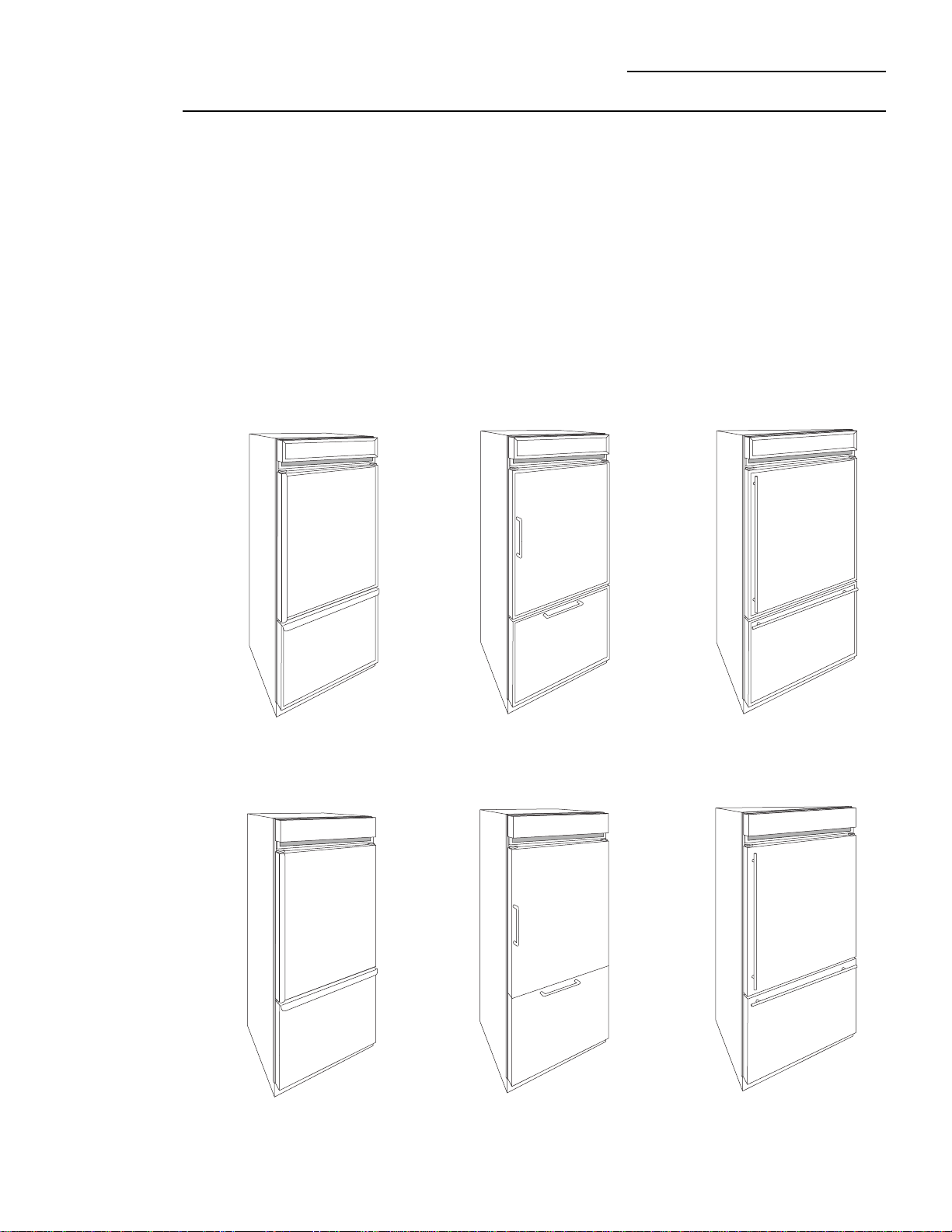
3/4" Custom panels with
Tubular Stainless Steel
handles, Trim Kits
ZKTC36L (or ZKTC36R)
and ZKHTCSSI
1/4" Panels with standard
handles. No kits required.
1/4" Custom panels with
custom handles. Trim Kit
ZKHC1.
1/4" Custom panels with
Tubular Stainless Steel
handles, Trim Kit
ZKHCSS1.
3/4" Custom panels with
supplied handle. Trim Kit
ZKTC36L (or ZKTC36R)
3/4" Custom panels with
custom handles. Trim kits
ZKTC36L (or ZKTC36R)
and ZKHTC1.
7
Custom Panel Dimensions
36" Bottom Mount Refrigerators
ZIC36N Bottom Mount Refrigerator
Design Information
Designed to be installed flush or semi-flush with
surrounding cabinetry. Cutout dimensions, clearances
and side panel sizes are determined by the many
installation options available. Side panels must be used
whenever the sides of the refrigerator will be exposed.
Side panels are not required when refrigerator is
installed into an enclosure or between pantry and oven
cabinets. IMPORTANT - Side panels, 1/2" minimum
thickness are required when using FRAMELESS
CABINETS.
• Field installed custom panels, Lexan
®
or stainless
steel panels are required. The door panels and grille
panel sizes vary to accommodate the kit being used.
• The supplied toekick is vented and must remain
unobstructed for proper air circulation.
Optional Panel Kits:
• ZWBC36: Black Lexan
®
Panel Kit
• ZWWC36: White Lexan
®
Panel Kit
• ZWSC36: Stainless Steel Panel Kit
Optional Custom Trim Kits:
• ZKHC1: For installation of a custom handle of your
choice onto 1/4" Panels.
• ZKTC36L or ZKTC36R: For installation of 3/4" thick
custom panels.
• ZKHTC1: For installation of a custom handle of your
choice onto 3/4" thick panels. (This kit must be used in
combination with ZKTC36L or ZKTC36R.
• ZKHCSS1: Tubular Stainless Steel handles for 1/4"
thick panels.
• ZKHTCSS1: Tubular Stainless Steel handles for 3/4"
thick panels.
• ZGC2: 1/4" grille panel frame side pieces for 83-1/2
and 84-1/2" installation heights. Factory set height is
84".
Additional Specifications
• A 115 volt 60Hz., 15 or 20 amp power supply is
required. An individual properly grounded branch
circuit or circuit breaker is recommended. Install a
properly grounded 3-prong electrical receptacle
recessed into the back wall. Electrical must be
located on rear wall as shown.
• Water line can enter opening through the floor or
back wall. The water line should be 1/4" O.D. copper
tubing between the cold water line and water
connection location, long enough to extend to the
front of the refrigerator. Installation of an easily
accessible shut off valve in the water line is
recommended.
Clearances:
• If the refrigerator is to be installed in a corner:
A 4" clearance is required on the hinge side for a 90°
door opening and access to fresh food drawers. A 10"
clearance is required on the hinge side for removal of
pans.
7"
*Finished Width
Wall View
(not to Scale)
Locate Grounded
Electrical outlet
Within Solid
Area Above
84 1/2" max
83 1/2" min
Finished
Opening
74" From
Floor to
Bottom of
Electrical Area
5"
5"
3 1/2"
5"
3 1/2"
Locate Water
Supply Within
the Shaded
Area Below
7 1/2"
* 36" Min. for a flush installation into an enclosure.
* 35-1/2" Min. for a semi-flush installation into an enclosure.
Note: Additional cutout width may be required when side panels are
used. Add side panel thickness to the finished cutout width to
calculate rough-in width. See installation examples on page 4.
4"
24 3/4"
Side View
36" Overall"
35" Case
Front View
26 3/4"
73-1/2"
10 3/4" Max
10" Min
84 1/2" Max
83 1/2" Min
26"
8
Custom Panel Dimensions
36" Bottom Mount Refrigerators
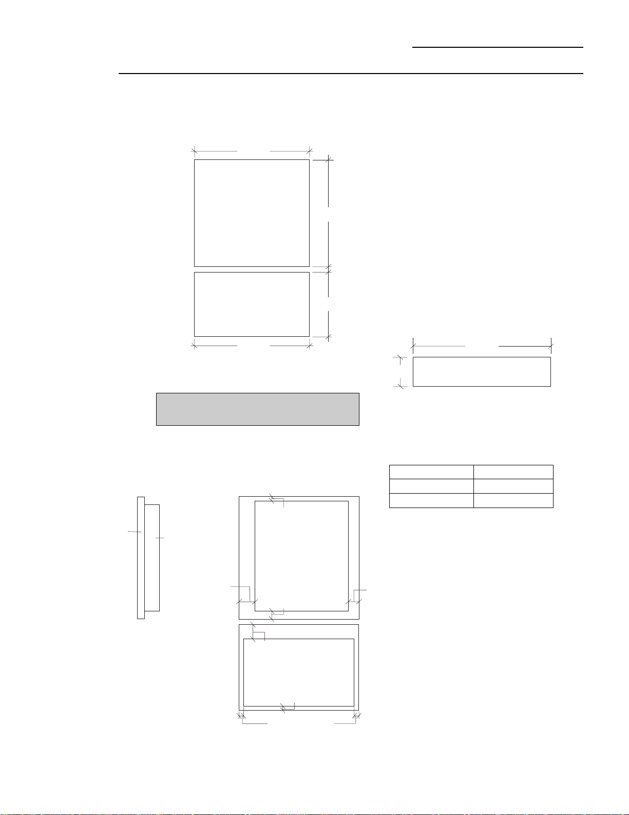
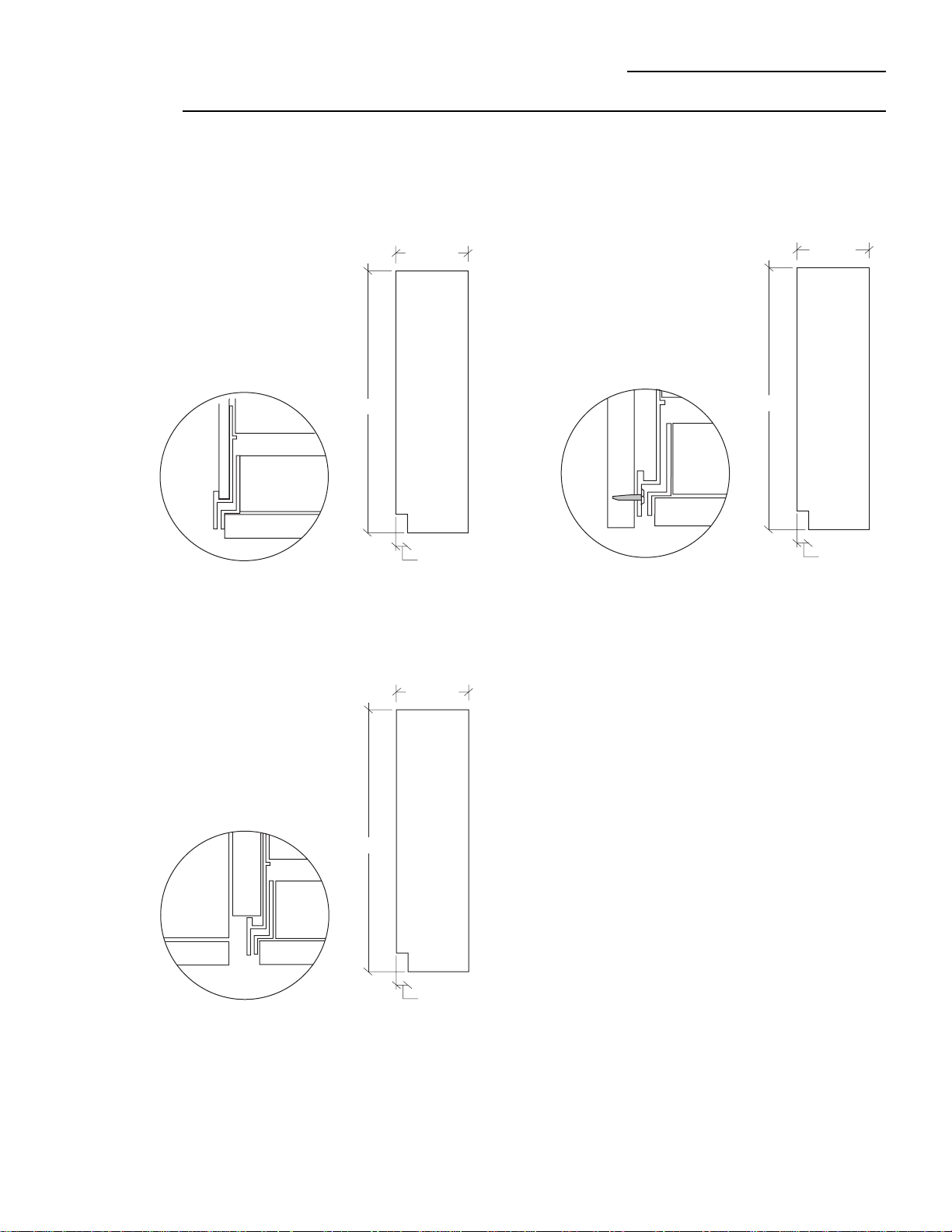
Custom Door Panel Dimensions Using Standard Trim
1/4" thick panels
or
Panels secured to 1/4" thick backing
ZIC36N Bottom Mount Refrigerator
• 1/4" Panels: Cut panels to size.
• Custom handles with 1/4" door panels require Trim kits
ZKHC1 or ZKHCSS1 for tubular stainless steel
handles).
Standard Trim with Panels secured
to 1/4" thick backing
• Applying a raised panel design to a 1/4" thick backing
(screws or glued): Cut 1/4" thick panels to size. On the
fresh food door, fabricate the raised panel to permit at
least 2" fingertip clearance of the standard handle. 1-
1/4" clearance from the hinge side to avoid striking
adjacent cabinetry and 5/16" from the top and bottom
edges to allow for the trim flange. For the freezer
drawer, allow 2" clearance at the top handle end and
5/16" clearance on both sides and the bottom edge to
allow for trim flange.
Note:
ZKHTC1 custom handle kit cannot be used in
this configuration.
Caution: Maximum weight for fresh food panel is
50 pounds and 30 pounds for freezer drawer panel.
1-1/4"
Clearance
hinge side
Appearance
Panel
1/4"
Thick
Backing
Raised Panel on 1/4" Thick Backing
Using Standard Handles
2" Clearance
handle Side
Fresh Food Panel
5/16" Clearance
5/16" Clearance
Freezer Panel
2" Clearance
Handle End
5/16" Clearance
5/16" Clearance
Installation Height Panel Height
83-1/2" 7-1/2"
84-1/2" 8-1/2"
35 1/8"
8" 1/4" Thick Panel
Custom Grille Panel
The grille panel frame is factory assembled for 84"
installation height. If installation height varies, order
ZGC2 trim kit that provides optional side trim pieces.
Cut grille panel to sizes shown below.
Fresh Food Panel
Freezer Panel
35 1/8"
35-1/16"
21 11/16"
45 1/2"
9
Custom Panel Dimensions
36" Bottom Mount Refrigerator
ZIS36N Bottom Mount Refrigerator
• The ZKTC36L (or ZKTC36R) trim kit provides for the
installation of 3/4" thick custom door and grille panels,
using the supplied handle. Cut panels to size and
install.
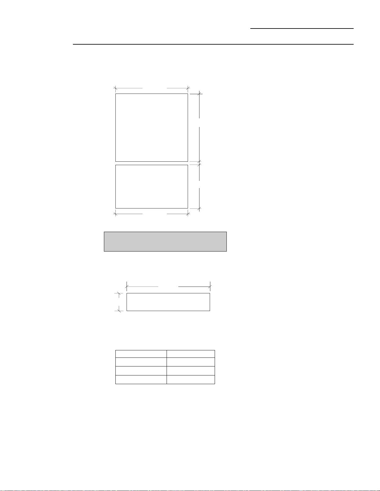
Custom Door Panel Dimensions
Using Trim Kits ZKTC36L or ZKTC36R
3/4" thick panel with kit supplied handle
Installation Height Dimension A
83-1/2" 7-3/4"
84" 8-1/4"
84-1/2" 8-3/4"
Important:
Maintain 1-1/2" min. gap between
top of door and bottom of grille panel.
Grille Panel height can vary to fill installation
height.
Caution: Maximum weight for fresh food panel is
50 pounds and 30 pounds for freezer drawer panel.
Fresh Food Panel
Freezer Panel
35 -1/4"
35 -1/16"
21-11/16"
45-9/16"
35 1/4"
A
3/4" Thick Panel
Custom Grille Panel
10
Custom Panel Dimensions
36" Bottom Mount Refrigerators
ZIC36N Bottom Mount Refrigerator
• The ZKTC36L (or ZKTC36R) trim kit installed together
with a ZKHTC1 custom handle kit provides for the
installation of 3/4" thick custom door and grille panels
with a custom handle of your choice. Order
ZKHTCSS1 for tubular stainless steel handles. Cut
panels to size, rout the handle side of the panels as
shown below and install.
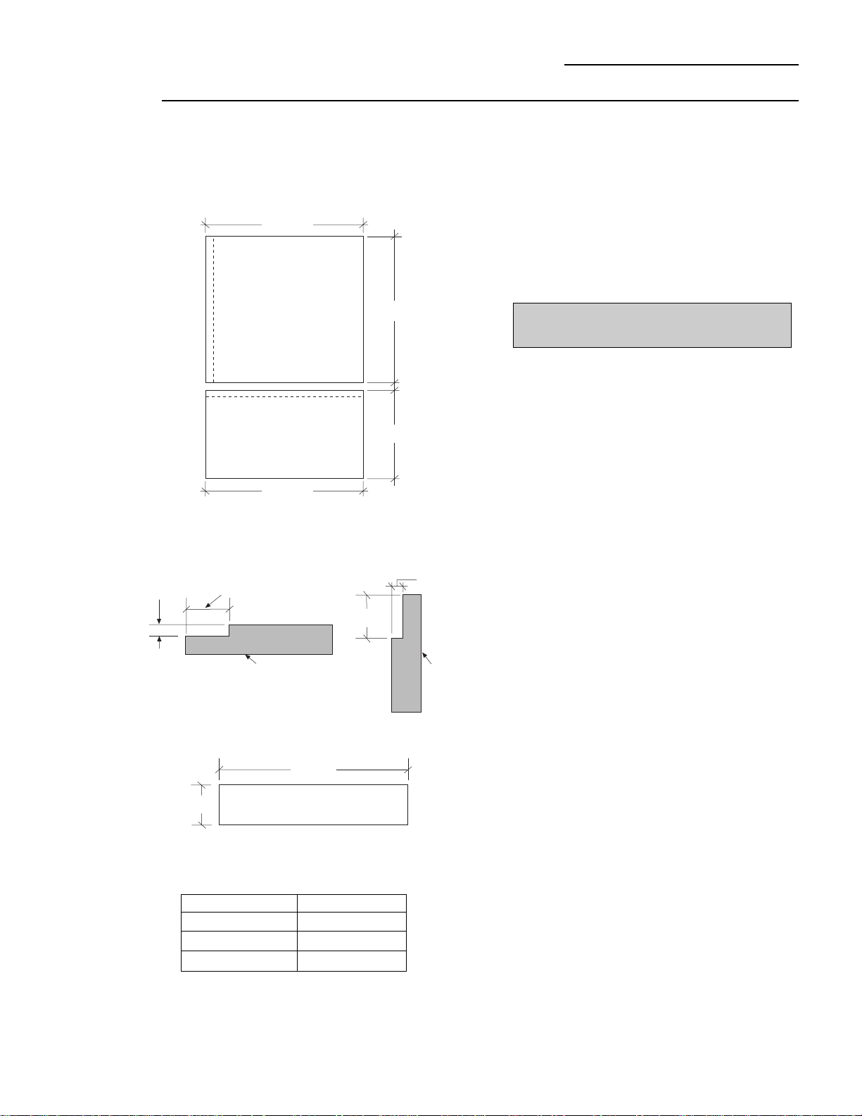
Custom Door Panel Dimensions Using Standard Trim
Using Trim Kit ZKTC36L or ZKTC36R
3/4" thick panel
with custom handle
Caution: Maximum weight for fresh food panel is
50 pounds and 30 pounds for freezer drawer panel.
1 13/16"
1/4"
max
Fresh Food Door Face
Rout panels to specification below on
the handle side of each panel
1 13/16"
Freezer
Door
Face
1/4" max
Installation Height Dimension A
83-1/2 " 7-3/4"
84" 8-1/4"
84-1/2" 8-3/4"
Important:
Maintain 1-1/2" min. gap between
top of door and bottom of grille panel.
Grille Panel height can vary to fill installation
height.
Fresh Food Panel
Freezer Panel
35 1/4 "
35 1/4 "
21 13/16"
45 9/16"
35 1/4"
A
3/4" Thick Panel
Custom Grille Panel
11
Custom Panel Dimensions
36" Bottom Mount Refrigerators
Side Panel or Filler Options
(Not to scale)
Side panels must be used whenever the sides of the
refrigerator will be exposed.
23 9/16"
84"
2 9/16"
Trim
24 3/4"
84"
3 3/4"
23 5/16"
84"
2 5/16"
1/4" Side Panels
Insert end of
side panel into trim.
Standard 4" high toekick or trim to fit.
Height may vary depending on application.
1/2" to 3/4" Side Panels
Recessed front edge.
Standard 4" high toekick or trim to fit.
Height may vary depending on application.
1/2" to 3/4" Side Panels
Leading Edge
Flush with Cabinet
Front. The front or
leading edge must be
finished to match
cabinetry.
Standard 4" high toekick or trim to fit.
Height may vary depending on application.

Installation
36" Bottom Mount Refrigerator
• Bucket
• Level
• Appliance Hand Truck
• Tubing cutter
• 7/16" open-end wrench
• #2 Phillips screwdriver
• Stubby Phillips
screwdriver
• Drill and appropriate bits
• 7/16" socket with 3"
extension for ratchet
• Safety glasses
• 1-1/2" stamped open-end wrench
• Special Velcro adhesive strips for 1/4" side panels
• 1/4-1/4 union with nuts
• Water shut-off valve (optional but recommended)
• Water filter WR97X0214 (optional but recommended)
• Custom panels for fresh food, freezer drawer, grille
panel
For proper installation, this refrigerator must be placed
on a level surface of hard material that is at the same
height as the rest of the flooring. This surface should be
strong enough to support a fully loaded refrigerator.
CAUTION: Protect the finish of the flooring. Cut a large
section of the cardboard carton and place under the
refrigerator where you are working.
CAUTION: Attaching the adapter ground terminal to a
wall outlet cover screw does not ground the appliance
unless the cover screw is metal, and not insulated, and
the wall outlet is grounded through the house wiring.
You should have the circuit checked by a qualified
electrician to make sure the outlet is properly
grounded.
When disconnecting the power cord from the adapter,
always hold the adapter in place with one hand and
pulling the power cord with the other hand. If this is not
done, the adapter ground terminal is very likely to break
with repeated use.
Should the adapter ground terminal break, DO NOT USE
the appliance until a proper ground has again been
established.
Use of Extension Cords
Because of potential safety hazards under certain
conditions, we strongly recommend against the use of
an extension cord. However, if you still elect to use an
extension cord, it is absolutely necessary that it be a UL
listed 3-wire grounding type appliance extension cord
having a grounding type plug and outlet and that the
electrical rating of the cord be 15 amperes (minimum)
and 120 volts.
IMPORTANT - (Please read carefully)
FOR PERSONAL SAFETY, THIS APPLIANCE MUST BE
PROPERLY GROUNDED.
The power cord of this appliance is equipped with a
three-prong (grounding) plug which mates with a
standard three-prong (grounding) wall receptacle to
minimize the possibility of electric shock hazard from
this appliance.
Have the wall outlet and circuit checked by a qualified
electrician to make sure the outlet is properly
grounded.
Where a standard 2-prong wall outlet is encountered, it
is your personal responsibility and obligation to have it
replaced with a properly grounded 3-prong wall outlet.
DO NOT, UNDER ANY
CIRCUMSTANCES, CUT
OR REMOVE THE THIRD
(GROUND) PRONG
FROM THE POWER CORD.
Use of Adapter plug
Because of potential hazards under certain conditions,
we strongly recommend against use of an adapter plug.
However, if you still elect to use an adapter, where
local codes permit, a TEMPORARY CONNECTION, may
be made to a properly grounded 2-prong wall outlet by
use of a UL listed adapter available at most hardware
stores.
The larger slot in the adapter must be aligned with the
larger slot in the wall outlet to provide proper polarity in
the connection of the power cord.
• Side panels
• Hardware for side panel installation.
• 36" long 2x4 for Anti-Tip support
• Anti-Tip Mounting Brackets
12
Tools
Required
• Tinsnips to cut banding
• Stepladder
Materials
Required
Hardware
Supplied
Flooring
Grounding
the
Refrigerator
13
Installation
36" Bottom Mount Refrigerator
CAUTION: Refrigerator is much heavier at the top than
at the bottom – be careful when moving. When using a
hand truck, handle from side only.
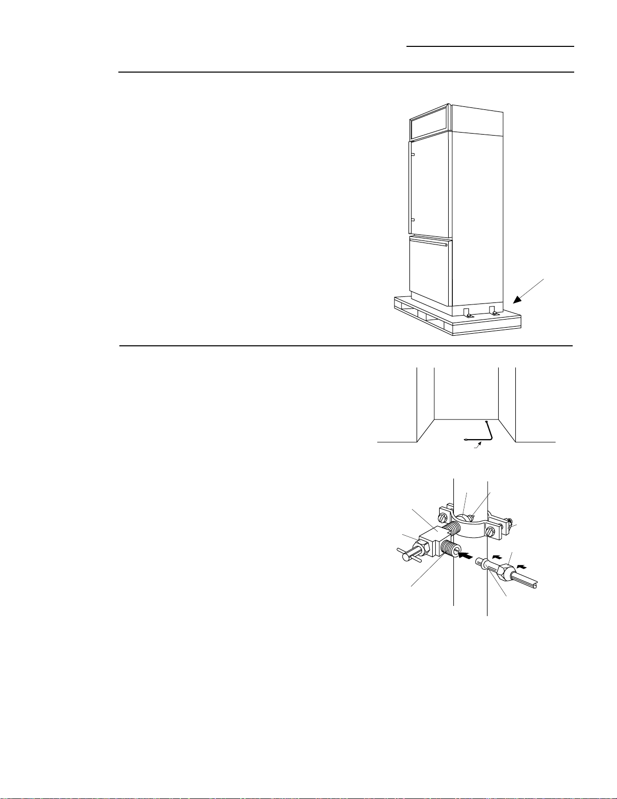
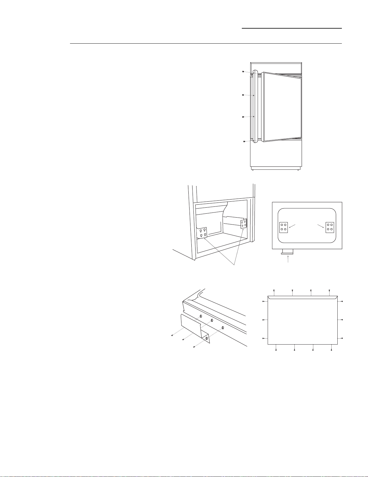
• Remove outer carton.
– Carefully cut banding at the top and bottom.
• Slide out back corner posts (2).
• Slide carton off top of cabinet.
NOTE: IT IS NOT NECESSARY TO LAY CABINET DOWN
IN ORDER TO REMOVE SKID!
• To remove skid, remove the four 7/16" bolts and their
brackets.
CAUTION: DO NOT ATTEMPT TO ROLL UNIT OFF SKID.
• There are support blocks on the bottom of the cabinet
and door. They must be removed before sliding unit off
skid or damage will occur.
• Carefully, tilt cabinet and slide blocks out from
beneath cabinet, slide unit off skid.
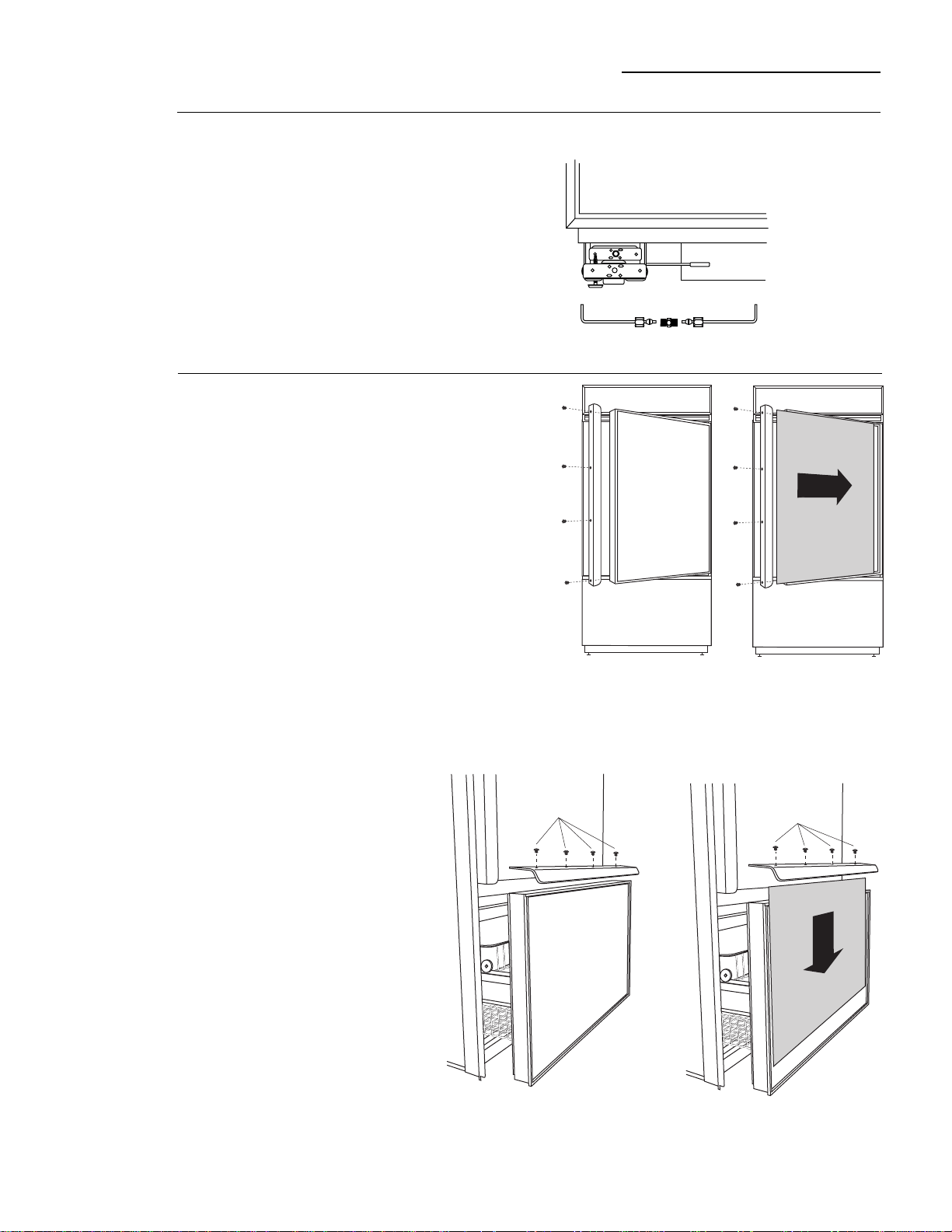
• Remove toekick from the fresh food compartment, set
aside for later installation.
Step 1
Remove
Packaging
Step 2
Install
Water Line
NOTE: Saddle type shut-off valves are included in
many water supply kits. Before purchasing, make sure
a saddle type valve complies with your local plumbing
codes.
• Install optional water filter in the water line near the
refrigerator. A water filter is recommended in areas
where water supply contains sand or particles.
Installation instructions are packed with the filter.
• A cold water supply is required for automatic
icemaker operation. The water pressure must be
between 20 and 120 p.s.i.
• Route 1/4" OD copper tubing between house cold
water line and the water connection location.
• Copper tubing should be long enough to extend to the
front of the refrigerator. Allow enough to accommo-
date bend leading into the water valve.
Shut off the main water supply.
Turn on the nearest faucet long enough to clear the line
of water.
Install a shut-off valve between the icemaker water
valve and cold water pipe in a basement or cabinet.
The shut-off valve should be located where it will be
easily accessible.
NOTE: It is best to install the valve into a vertical water
pipe. If you install the valve into a horizontal water pipe,
make the connection at the top or side, rather than at
the bottom, to avoid drawing off any sediment from the
water pipe.
• Drill a 1/4" hole in the water pipe.
• Fasten the shut-off valve to the pipe with pipe clamp.
• Tighten the clamp screws until the sealing washer
begins to swell. Do not over tighten.
• Place a compression nut and ferrule (sleeve) onto the
end of the tubing and connect it to the shut-off valve.
Make sure the tubing is fully inserted into the valve
and ferrule is tightened.
• Turn on the main water supply and flush debris from
the line. Run about a quart of water through the tubing
into a bucket. Shut off water supply at the shut-off
valve.
7/16" Bolt
Floor
Copper Tubing
Saddle Type
Shutoff Valve
Compression Nut
Ferrule
(Sleeve)
Outlet Valve
Packing Nut
Inlet End
Pipe Clamp
Washer
14
Installation
36" Bottom Mount Refrigerator
Step 3
Install
Side Panels
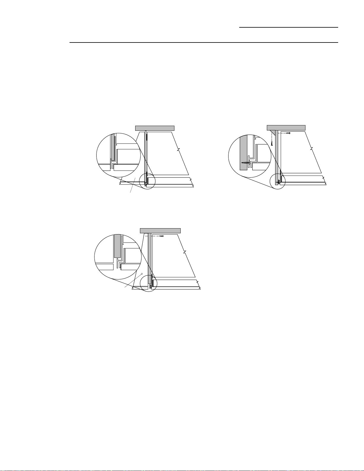
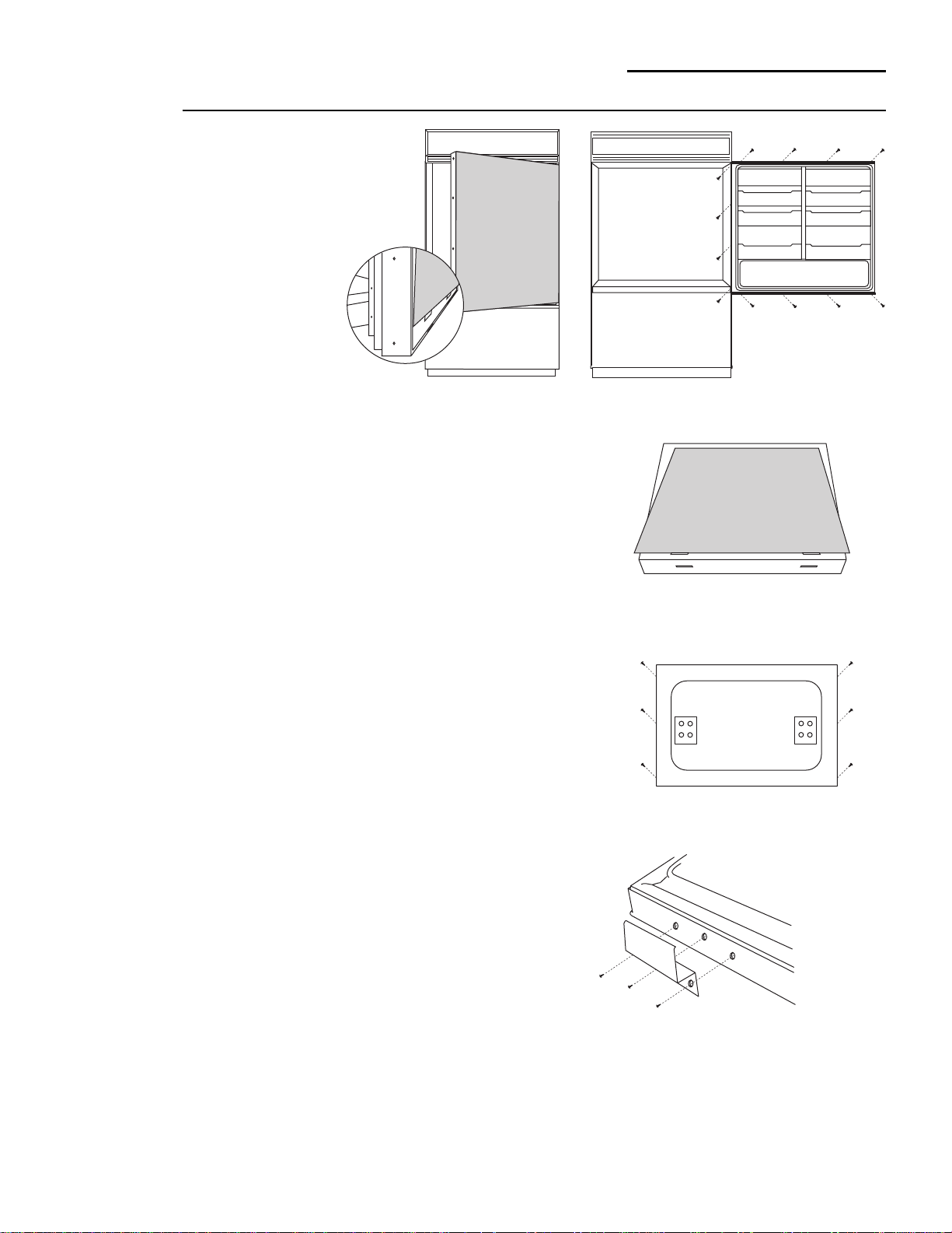
• Side panels are not required when the refrigerator is
installed into an enclosure. Skip this step if you are
installing into an enclosure.
• Side panels are required whenever the sides of the
refrigerator will be exposed and when installed
between frameless cabinets. See pages 3 and 4.
• Side panel installation will be determined by the
design of the side panel you have previously chosen.
• Side panels must be installed plumb.
• If you choose to use 1/4" side panels, they should be
inserted into the case trim as illustrated. Fasten the
panels to the refrigerator with Velcro strips (provided)
before setting refrigerator in place. See illustration A.
• 1/2" to 3/4" side panels are normally set into place and
fastened to adjacent cabinetry or the back wall before
rolling the refrigerator into the opening. See illustra-
tions B and C.
1/2" to 3/4" Side Panels - Leading edge of side panel is
flush with cabinet front. Fasten to the back wall using a
cleat.
1/4" Side panels - Insert end of side panel into case
trim. Fasten with Velcro strips provided.
1/2" to 3/4" Side Panels - Recessed front edge of side
panel. Fasten to adjacent cabinet.
Cabinet
Refrigerator door
Refrigerator
Cabinet
Refrigerator
Cabinet
Refrigerator door
Cabinet
Refrigerator
Cabinet
Refrigerator door
Illustration A
Illustration C
Illustration B
15
Installation
36" Bottom Mount Refrigerator
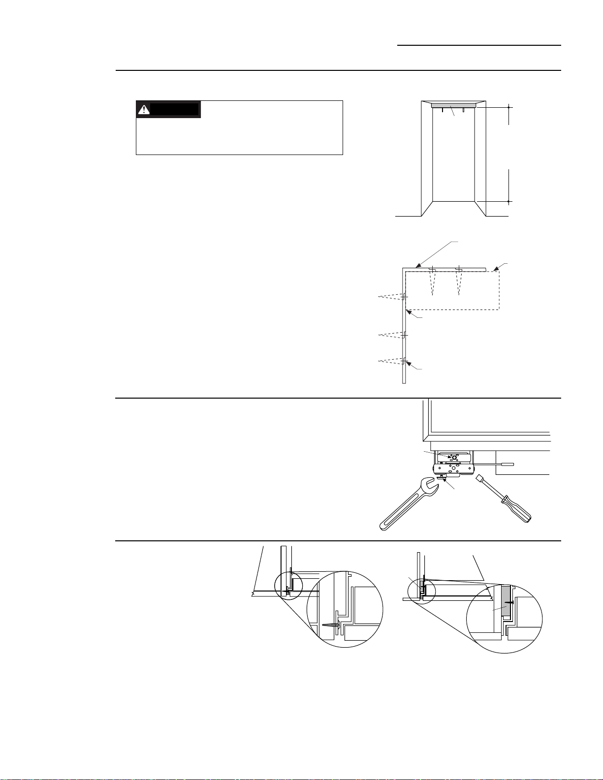
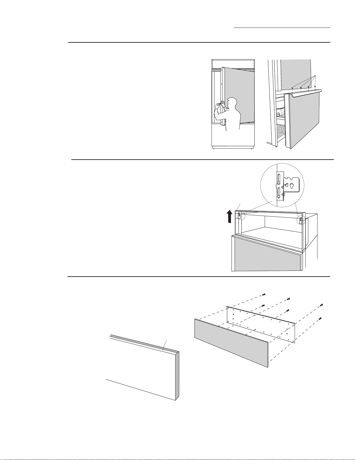
ANTI-TIP PRECAUTIONS
The refrigerator is heavy at the top and must be
secured to prevent the possibility of tipping forward.
• Mount brackets provided using #12 or #14 wood
screws located 83-1/2" from the finished floor.
• Screws must protrude at least one inch into vertical
wall studs.
• Attach a 36" long 2x4 block to brackets as shown.
Note:
If you are installing under a soffit, attach brackets to
wood block before mounting the brackets to the rear wall.
Roll Refrigerator Into Opening
• Gently push refrigerator into opening with hands
against front corners. The cardboard protective pad
should be beneath the refrigerator.
• Roll refrigerator into the opening until it is flush or
semi-flush with adjacent cabinets.
Important Note:
If your installation situation does not allow
enough height for this method of security, use step 6 as an
alternate. The refrigerator must be secured to prevent
tipping.
Step 4
Install
Anti-Tip
Brackets
Step 5
Level
Refrigerator
All models have 4-point leveling. The front is supported
by leveling legs, the rear is supported by wheels.
• Adjust rear wheels beneath the refrigerator to just
barely touch the 2x4 block.
• Turn the 7/16" hex nut located above the front wheels.
Turn to raise or lower the refrigerator.
• For front leveling legs, use the 1-1/2" open-end
wrench (provided).
• Adjust carefully, the refrigerator should be level and
plumb with cabinetry, and should align with toekick
height.
Mounting Bracket
2 x 4 Cut
To 36" Length
83-1/4" From Floor
Wood Screws Mounted into
Vertical Wood Studs
Step 6
Optional
Anti-Tip
Precaution
Leveling Leg
Hex Nut Adjusts
Rear Wheels
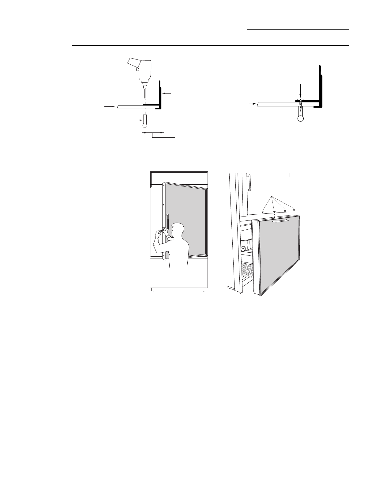
When using 1/2" to 3/4" side panels, the front flange of
the case trim is attached to the side panel.
• Open fresh food door to access case trim.
• Drill hole in trim slightly below fresh food opening.
Drive screw through the trim and into the side panel.
• Follow the same procedure on the opposite side.
If refrigerator is installed between cabinets with no
side panels or in a custom enclosure, install a spacer
block as shown.
• Open fresh food door to access case trim.
• Drill hole in trim slightly below fresh food opening and
drive screw through the trim and into the spacer
block.
• Follow the same procedure on the opposite side.
Note:
Whenever possible,
perform this step for
additional anti-tip
security.This step can be
used as an alternate to Step
4, Anti-Tip bracket installa-
tion, whenever brackets
cannot be used.
Stud
Spacer
Block
Refrigerator
Cabinet
Door
OR
CAUTION
WARNING
2 x 4
Block
36" Wide
83-1/2"
From floor
to bottom
of wood block
16
Installation
36" Bottom Mount Refrigerator
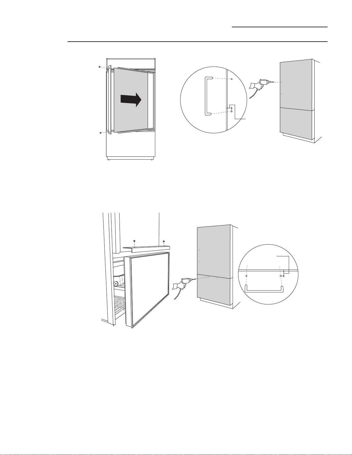
Step 8
Install 1/4"
door panels
If you are using 3/4" thick custom panels, SKIP THIS
STEP. See Custom Panel Dimensions pages for panel
sizes with ZKTC36L or ZKTC36R trim kit and other kits.
Refer to trim kit installation instructions in this booklet.
Fresh food door panel:
• Open door to 90° stop. Remove the Phillips head
screws from the aluminum trim door handle.
• Remove handle. Retain all screws.
• Slide custom panel into the door trim.
• Replace door handles and secure with original
screws.
Freezer drawer panel:
• Slide freezer drawer out about half way.
• Remove the Phillips head screws from the aluminum
trim door handle.
• Lift off handle. Retain screws.
• Slide custom panel into
the drawer trim.
• Replace the drawer handle
and secure with
original screws.
Step 7
Connect
Water
Supply
Check to be sure that refrigerator power cord is not
plugged into the wall outlet.
• Locate and bring copper tubing to the front of the
cabinet.
• The copper tubing should be just long enough to
reach the coupling. Excess tubing length could interfer
with drawer closing or toekick installation.
• Slip a 1/4-1/4 union nut (provided) over both ends of
the copper tubing at the right front leg of the refrigera-
tor and couple the lines.
• Turn on the water to check for leaks.
Remove
4 Screws
Install
Original
Screws
17
Installation
36" Bottom Mount Refrigerator
Step 9
Connect
power
• Connect refrigerator power cord plug to a properly
grounded receptacle, accessible through the top left
side of the grille opening.
• Check to make sure power to refrigerator is on by
opening refrigerator door to see if interior lights are
on.
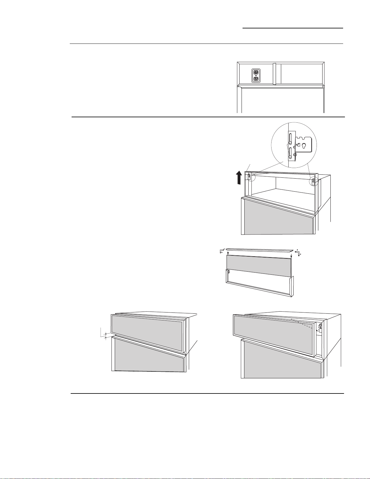
If you are using 3/4" thick custom panels, SKIP THIS
STEP. See Dimensions and Specifications for grille
panel sizes. Order ZKTC36L or ZKTC36R and follow the
installation instructions packed with the kit.
The grille panel frame is factory assembled for an 84"
installation height. If installation height varies, order
ZGC2 trim kit which provides optional side trim pieces
for 83-1/3" and 84-1/2" heights.
Cut 1/4" thick custom panel to fit the frame,
35-1/8" wide, 8" deep (for an 84" installation).
• For shipping purposes, the top case trim is secured at
84" installation height and must be adjusted.
To raise case trim to 84-1/2" or to lower to 83-1/2"
installation height:
• Loosen 2 screws on both sides and raise the top or
lower case trim to meet soffit height or to the top of
adjacent cabinets.
• Tighten all 4 screws.
To insert custom grille panel into the frame:
• Remove screws (2 on each top corner) and “L”
brackets on each side.
• Slide panel into the frame and reassemble.
• Mount the grille panel by dropping into slots on the
case trim.
Step 10
Mount
Top Grille
Panel
Important
: Maintain 1-1/2" min. gap between top of doors and
bottom of panel frame.
• A standard toekick is supplied. Install with 2 screws
provided, adjust to desired height and tighten screws.
Important:
The vented toekick must remain unobstructed
for proper air circulation and operation.
Step 11
Install
Toekick
Screws
Top
Case
Trim
Raise To
Installation
Height
1-1/2"
min.
gap
ZGC2 Trim Kit
Grille panel frame adjustment
18
This kit provides optional side trim pieces for the
original grille panel frame to fit 83-1/2" and 84-1/2"
installation heights.
To change grille panel size:
• Determine the installation height by measuring the
enclosure from the floor to the underside of soffit.
When there is no soffit, measure to the top of the
adjacent cabinets.
• Adjust refrigerator case trim to desired height. See
Product Installation.
• Select the side trim pieces for your installation height.
A. Locate original grille panel frame supplied with the
refrigerator.
• Remove 8 screws (two on each corner) and “L”
brackets as illustrated.
B. Select correct set of side trim pieces (2 sets
provided).
• Secure new side trim pieces to original bottom trim.
C. Remove barrel nuts from original side trim pieces (2
each side).
• Reinstall the barrel nuts on the new side trim pieces
you have selected. Discard original side trim.
D. Slide custom panel into front slots.
• Secure the top trim piece to the frame with “L”
brackets and screws.
E. Mount the assembled panel by dropping into slots on
the case trim.
Important:
Maintain 1-1/2" min. gap between top of door
and bottom of grille panel.
Discard
Side Trim
Pieces
Barrel
Nuts
1-1/2"
min.
gap
19
ZKHC1 Trim Kit (for 1/4" Panels)
Support for custom handles
Tools and materials required:
• #2 Phillips screwdriver
• Drill and appropriate bits
• Custom door panels
• Custom Handles
• Safety glasses
Parts List:
A. Fresh food door extrusion (for left hand models)
B. Fresh food door extrusion (for right hand models)
C. Freezer drawer extrusion
This kit provides the necessary framework to install
custom handles, of your choice, onto 1/4" thick custom
panels. (Handles not included.) The extrusions in this kit
allow the custom handles to be secured to the door
structure, rather than the door panels.
• Select fresh food extrusion for your model, discard
other fresh food extrusion.
Step 1
Remove
handles
Right hand door swing models are illustrated in these
instructions. Follow these instructions for left hand
models.
Fresh food door:
• Open door to 90°. Remove the screws from the full
length aluminum handle.
• Retain screws. Discard handle.
Freezer drawer:
• Slide the freezer drawer open, about half way.
• Remove screws from the full-width aluminum handle.
Retain screws. Discard handle.
Remove
4 Screws
ZKHC1 Trim Kit (for 1/4" Panels)
Support for custom handles
20
Step 2
Locate
handle
positions
Freezer drawer:
• Slide custom panel into the freezer drawer trim.
• Temporarily secure the new handle extrusion to the
drawer using at least 2 screws.
• The handle must be located 3/4" to 1-1/2" from the
edge of the extrusion.
• Determine the location of the custom handle and
carefully mark centerlines of the screw holes.
• Drill 1/16" pilot hole through the panel until it starts
into the aluminum extrusion. This will mark the
matching location for drilling clearance holes when
assembling the handle, panel and extrusion.
• Determine the desired location of the custom handle
and mark centerlines of the screw holes.
• Drill 1/16" pilot hole through the panel until it starts
into the aluminum extrusion. This will mark the
matching location for drilling the clearance hole when
assembling the handle, panel and extrusion.
3/4" Min.
1-1/2" Max.
Fresh food door:
• Slide custom panel into the door trim.
• Temporarily secure the new handle extrusion to the
door using at least 2 screws.
• The custom handles must be located 3/4" to 1-1/2"
from the edge of the extrusion.
3/4" Min.
1-1/2" Max.
Install
2 Screws
21
ZKHC1 Trim Kit (for 1/4" Panels)
Support for custom handles
Step 3
Assemble
panel,
extrusion and
handle
Fresh food door:
• Remove the door extrusion and custom panel.
• Drill 1/16" pilot hole through extrusion.
• Drill clearance holes through the panel and extrusion.
• Assemble the door panel, extrusion and custom handle.
• Install screw(s) long enough to pass through the
extrusion, door panel and into the handle.
• Slide the assembly into the door frame until the new
extrusion fits firmly against the steel door.
• Reinstall original screws into the door extrusion.
Freezer drawer:
• Remove the handle extrusion and panel.
• Drill 1/16" pilot hole through extrusion.
• Drill clearance holes through the panel and extrusion.
• Assemble the door panel, extrusion and custom
handle.
• Install screws(s) long enough to pass through the
extrusion, door panel and into the handle.
• Slide the assembly into the drawer trim until the new
extrusion fits firmly against the steel drawer.
• Reinstall original screws into the extrusion.
Extrusion
3/4" Min.
1-1/2" Max.
Handle
Decorator
Door Panel
Screw
Decorator
Door
Panel
Install
4 Screws
Right hand door swing models are illustrated in these
instructions. Follow these instructions for left hand
models.
Tools and materials
required:
• #2 Phillips screwdriver
• Drill and appropriate
bits
• Custom door panels
• Putty knife
• Safety glasses
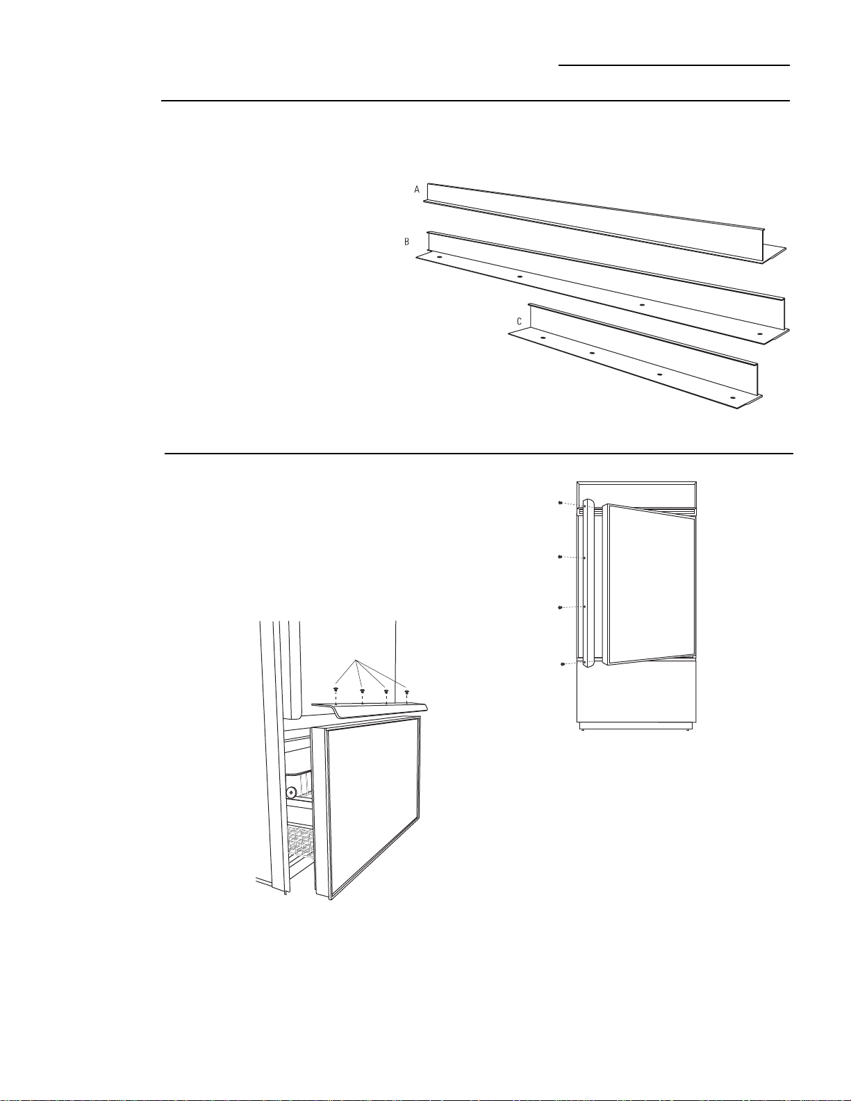
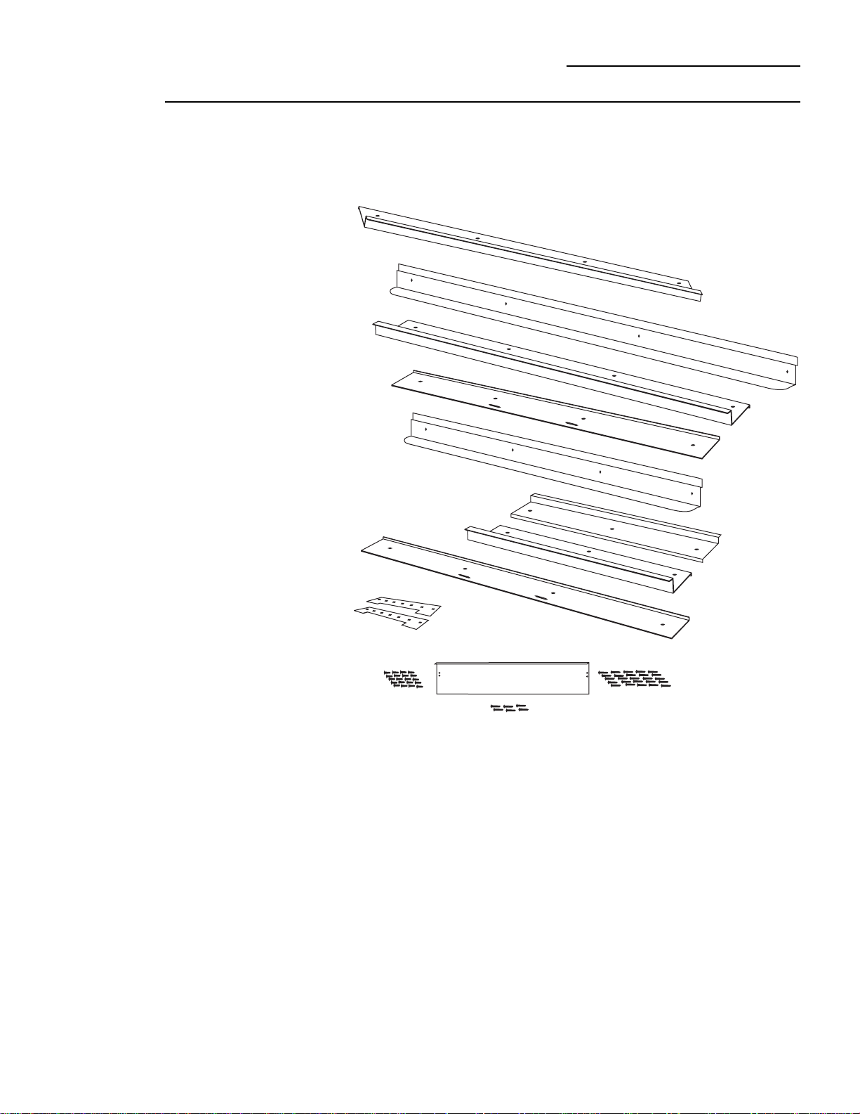
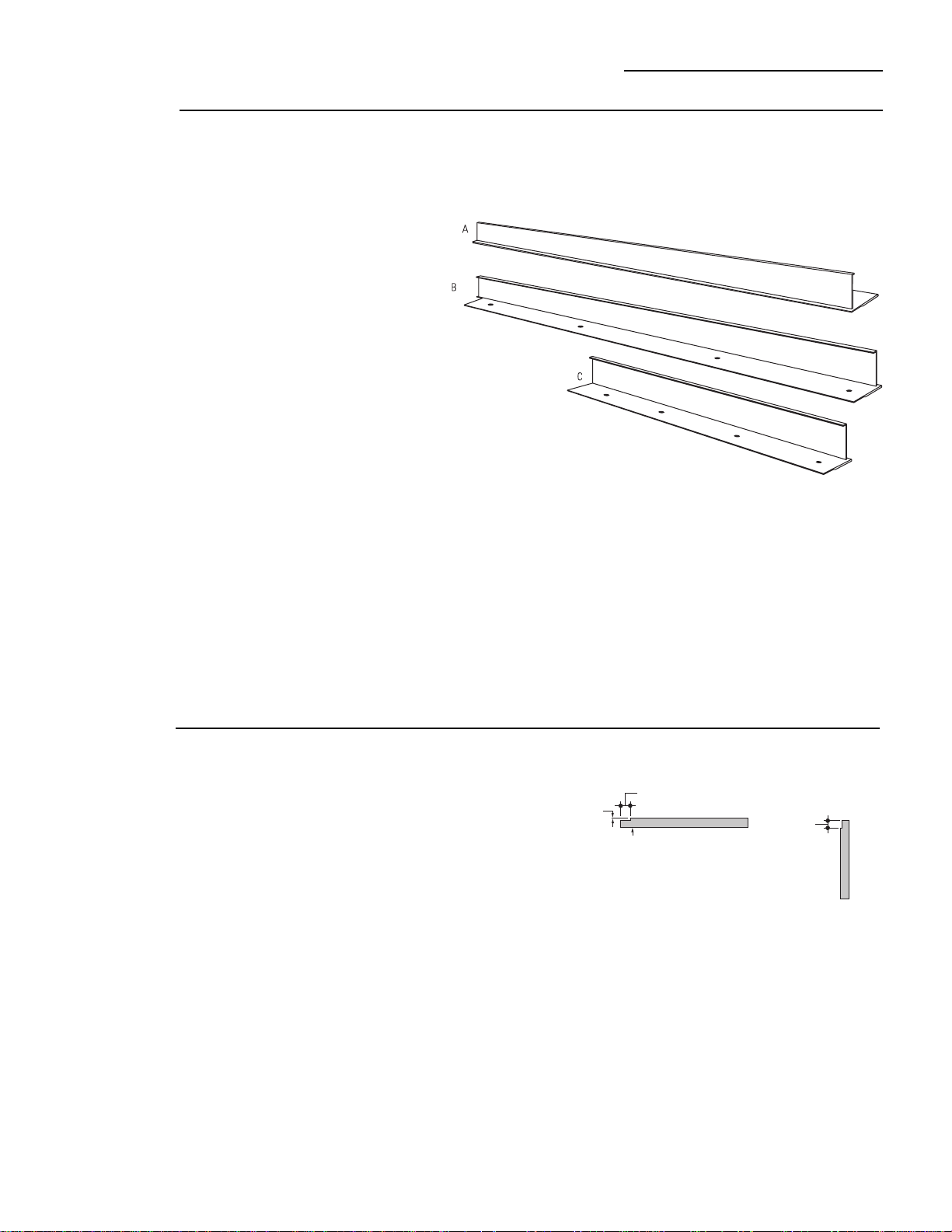
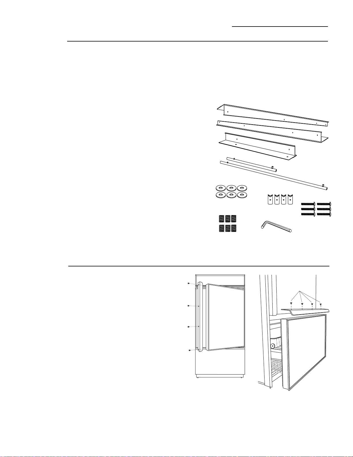
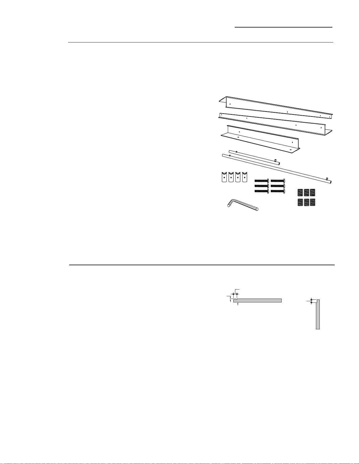
Parts List
A. Top trim
B. Fresh Food Handle
C. Hinge side trim
D Bottom trim
E. Freezer Handle
F. Side Trim
G. Side Trim
H. Bottom trim
I. Support brackets for
custom panels
J. 4-3/8" screws for
support brackets
(20)
K. Grille support
panel and screws
(6)
L. Wood screws #6
1/2" flat head
screws (30)
Note:
If you are using
custom handles, see
ZKHTC1 installation
instructions. For tubular
stainless steel handles, see
ZKHTCSS1 installation
instructions.
Kit Contents
ZKTC36L/ZKTC36R Trim Kit
3/4" Custom Panels
22
This kit provides for the installation of 3/4" thick custom
door and grille panels. Handles are included and must
replace the supplied handles.
A
B
C
D
E
F
G
H
I
J
K
L
23
ZKTC36L/ZKTC36R Trim Kit
3/4" Custom Panels
Step 1
Remove
handles
and trim
Fresh food door:
• Open door to 90°.
• Remove the Phillips head screws from the full length
handle, remove handle.
• Open the door fully to stop.
• Remove the screws from the aluminum trim, top
bottom, hinge and handle side.
• Retain screws. Discard original trim and handle.
Freezer drawer:
• Slide the drawer fully open.
• Lift out top and bottom freezer
baskets.
• There are 2 sets of 4 screws on
the inside of the drawer door.
Insert putty knife behind screw
cover and snap off. Retain screw
covers.
• Loosen all screws.
• Carefully, lift off entire drawer
door.
• Place door on a protected surface,
front side down. Take care not to
bend switch plate on the bottom of
the door.
• Remove light switch plate by
backing out 3 Phillips head
screws. Retain switch plate and
screws.
• Turn the drawer over, front side
up. Remove trim on both sides,
bottom and handle. Retain all
screws.
Inside Freezer Drawer
Attachment Screws
Light Switch Plate
Drawer Slides
Light Switch Plate
Front Face Freezer Drawer
24
ZKTC36L/ZKTC36R Trim Kit
3/4" Custom Panels
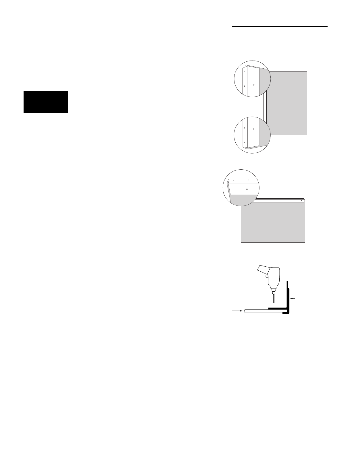
Step 2
Install
3/4" trim
Step 3
Apply panel
support
brackets
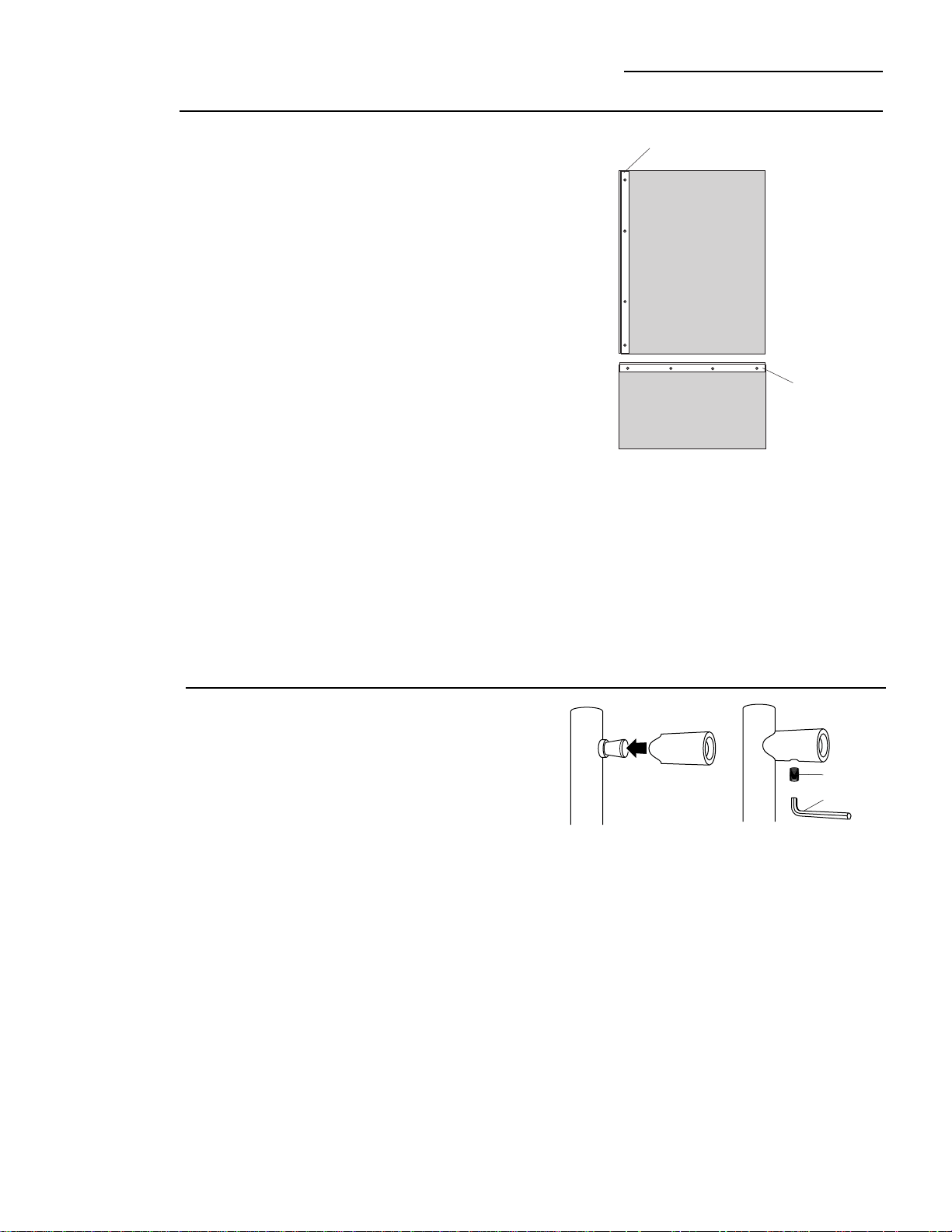
Fresh Food Door:
• Attach the new 3/4" trim pieces on the top, hinge side
and bottom using original screws.
Freezer Drawer:
• Attach the new 3/4" trim pieces on the bottom and
both sides.
• Position support bracket on the back side of the fresh
food panel, 14-5/16" from the hinge side. Secure
support bracket to panel with screws provided.
• Position support bracket on the back side of the
freezer drawer panel, 14-5/16" from the right side.
Secure support bracket to panel with screws
provided.
Front Face Freezer Drawer
14-5/16"
14-5/16"
Back Side Fresh Food Panel
Hinge
Side
Support Bracket
Bottom Edge
Back Side Freezer Drawer Panel
Support Bracket
Bottom Edge
25
ZKTC36L/ZKTC36R Trim Kit
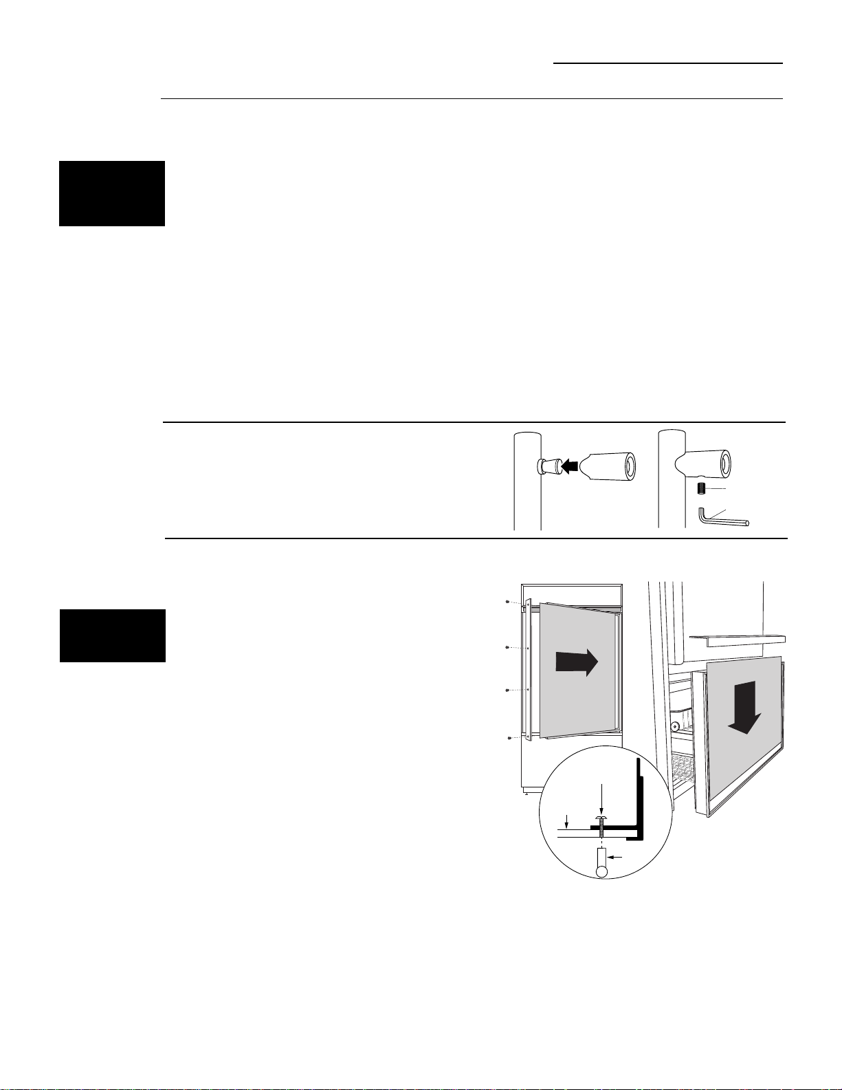
3/4" Custom Panels
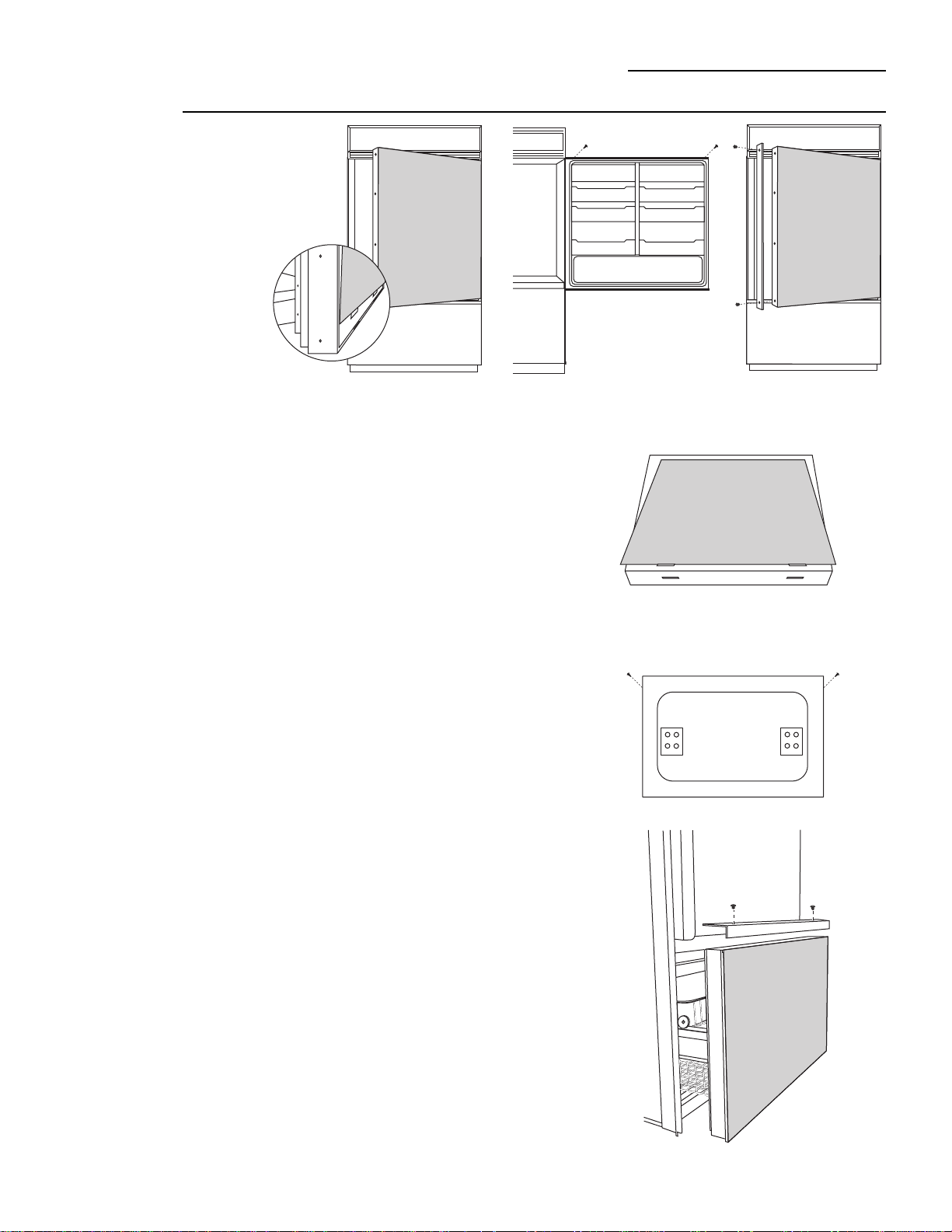
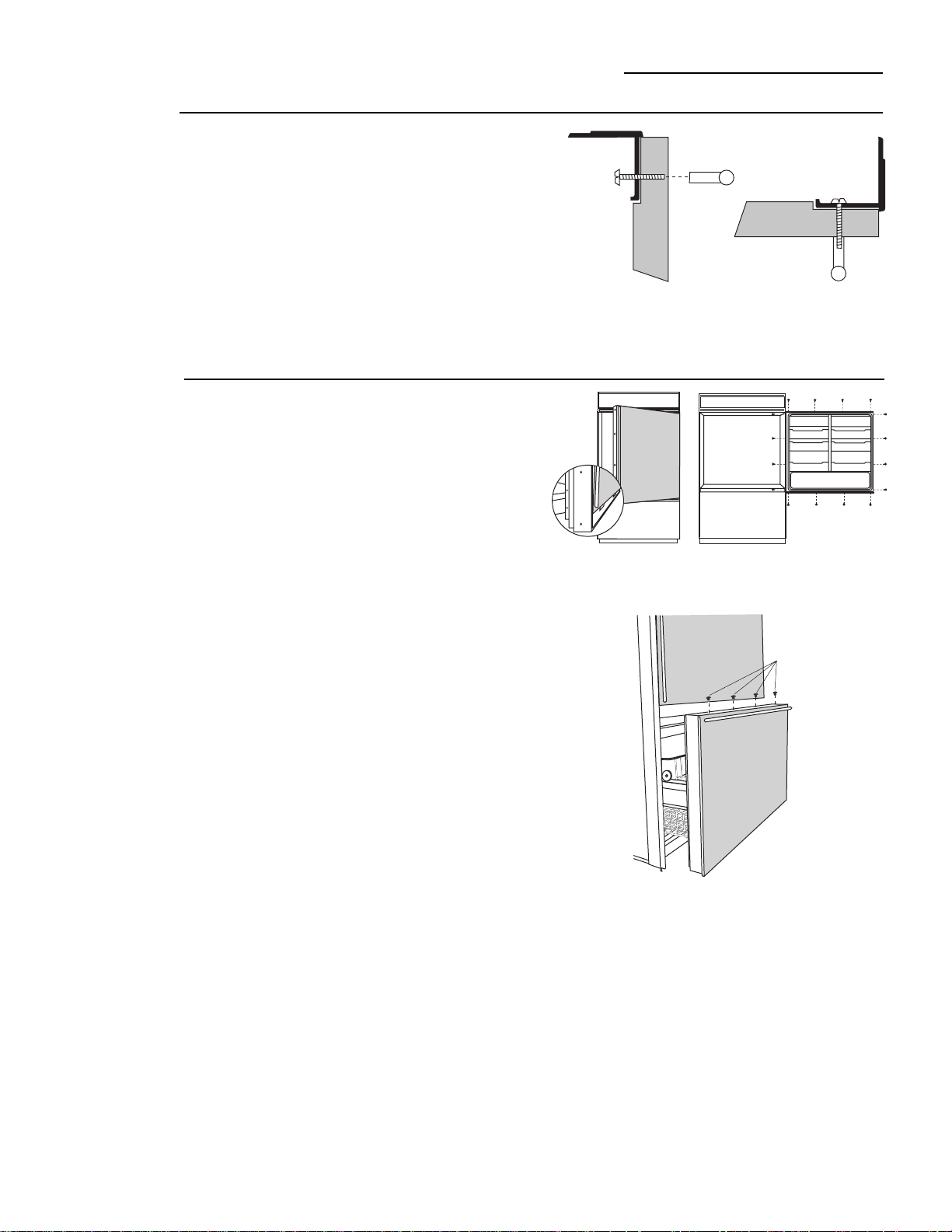
Step 4
Install
panels
Fresh Food Panel:
• Place the 3/4" thick panel on the bottom trim with
support bracket tabs inserted into slots. Push the
panel back against the steel door, flush with hinge
side trim.
• Open the door fully.
• Carefully drill 4 starter holes using a small drill bit,
through the backside of the trim at the top.
• Install original screws through the trim and into the
panel to secure the panel to the door.
• Drill 4 starter holes through the hinge side and 4
through the bottom trim. Install original screws.
Freezer panel:
• Place the 3/4" thick panel onto the door with the
support bracket tabs inserted into slots. The sides of
the panel should be flush with trim on both sides.
• Turn door over, panel side down. Attach the panel to
the sides and bottom by installing screws through the
back of the trim and into the wood panel.
• Reinstall light switch plate to the bottom trim with
original screws.
Inside Freezer Drawer
Insert support bracket tabs
into slots on bottom trim
Light Switch Plate
ZKTC36L/ZKTC36R Trim Kit
3/4" Custom Panels
Step 5
Install
handles
Step 6
Adjust
grille
panel height
• Install new fresh food door handle using original
screws.
• Place assembled drawer door onto freezer slides.
• Tighten screws and snap on screw covers.
• Install new freezer drawer handle with original
screws.
26
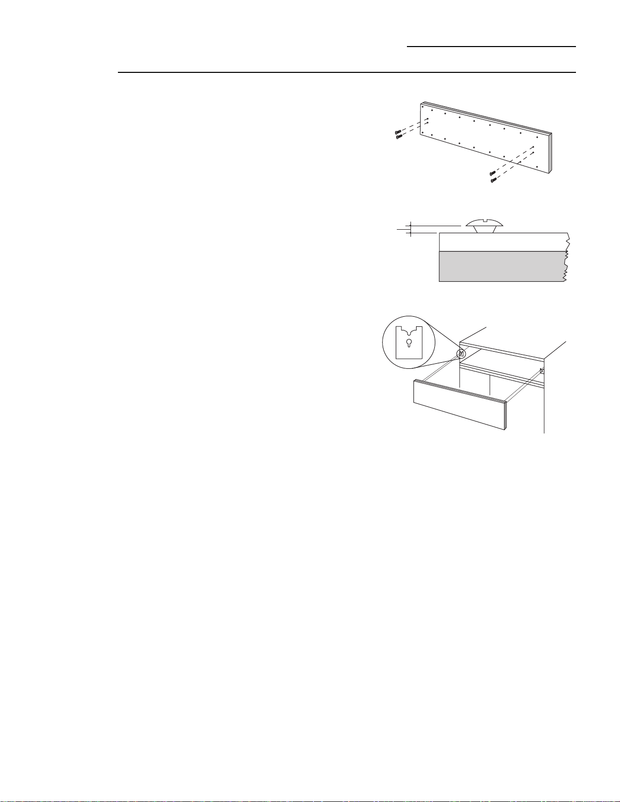
• Secure the grille panel support to the back side of the
3/4" custom panel with #6 screws.
• Be sure the lip of the support is over the top of the
wood panel.
Step 7
Secure 3/4"
panel to
grille panel
support
• For shipping purposes, the top case trim is secured at
the 84" installation height.
• Loosen 2 screws on both sides of the case trim and
raise or lower trim to meet soffit height, from 83-1/2" to
84-1/2".
• Tighten all 4 screws.
Important:
Maintain 1-1/2" min. gap between top of door
and bottom of grille panel.
Panel Support
Overlaps Top
Install
4 Screws
Screws
Top
Case
Trim
Raise To
Installation
Height
27
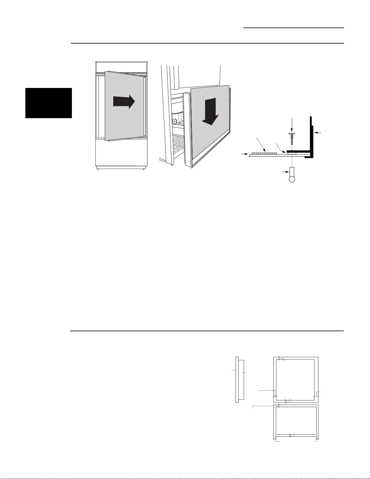
ZKTC36L/ZKTC36R Trim Kit
3/4" Custom Panels
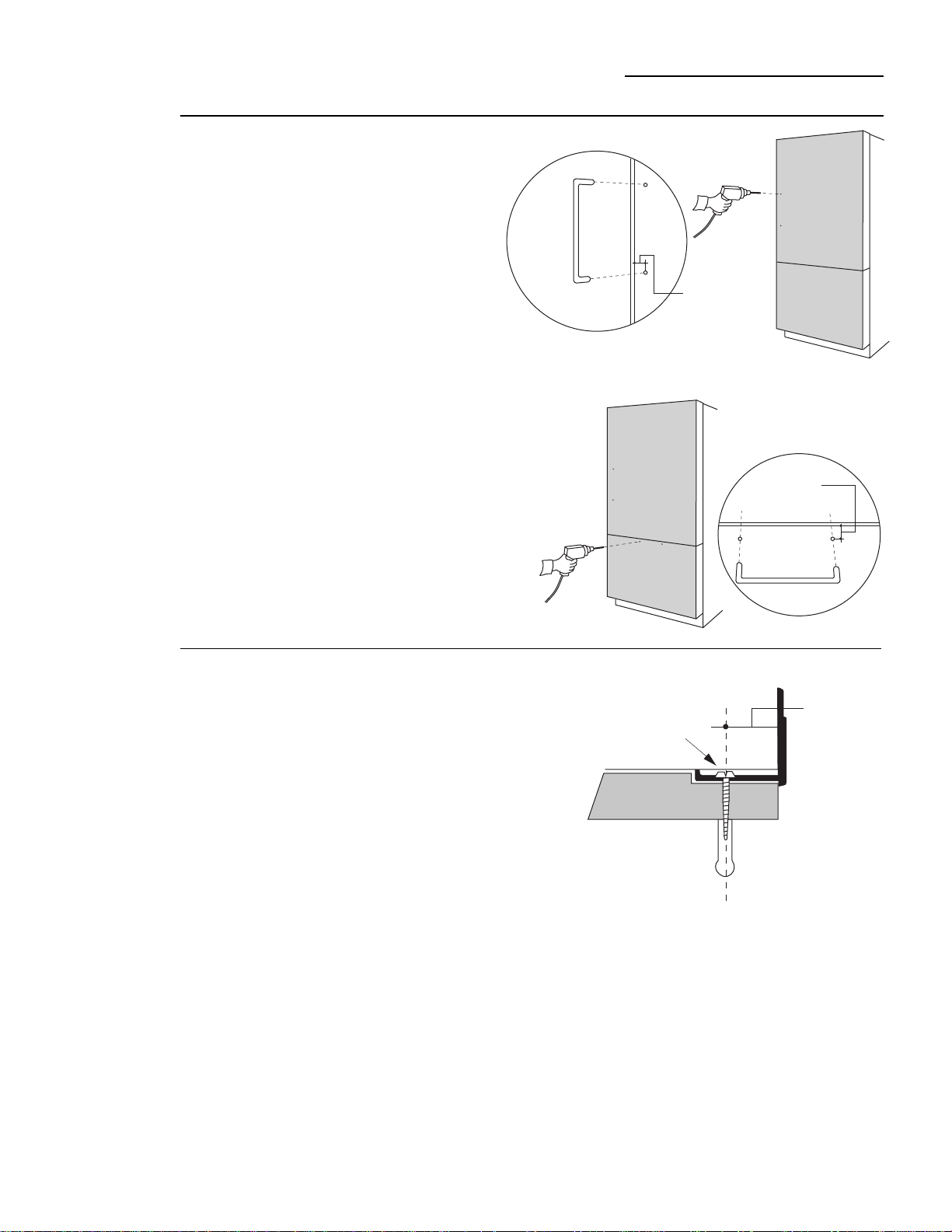
Step 8
Install
grille panel
• Install four of the six larger undercut screw so that the
top of the screws are 1/16" from the surface of the
support.
• Attach the assembled panel to the refrigerator by
inserting the four protruding screws into the brackets
on each side of the grille opening.
Back View
Grille Panel Support
1-1/16"
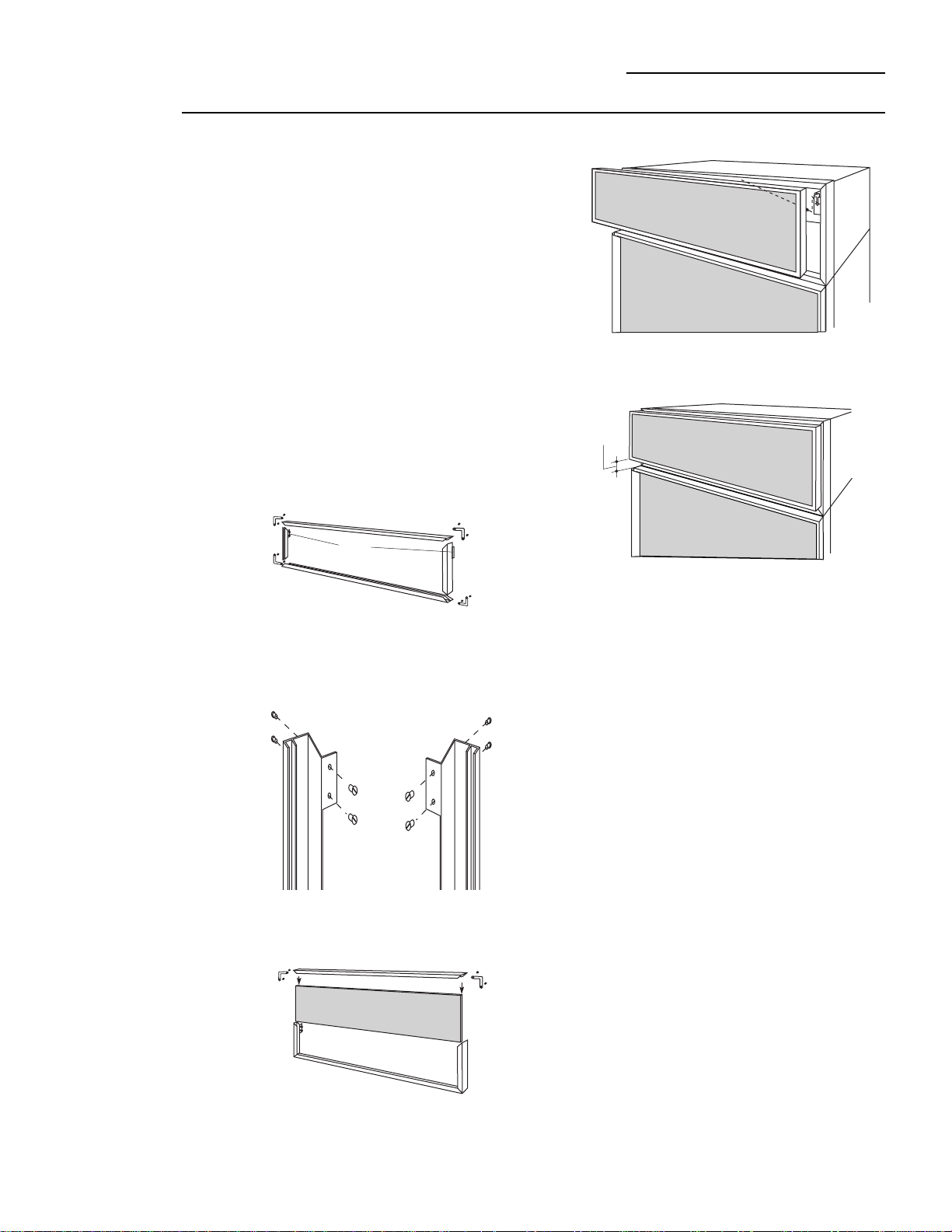
3/4" custom door panels must be routed to accommo-
date these door handle extrusions. Rout the panels as
illustrated, 1/4" deep, and 1-13/16" wide on the handle
side of the fresh food panel and the top end of the
freezer panel.
Refer to installation instructions for ZKTC36L or
ZKTC36R trim kit for 3/4" custom panels:
• Follow Step 1 to remove the standard aluminum trim.
• Follow Steps 2 and 3 to attach new 3/4" trim pieces
and to install panel support brackets.
Right hand door swing models are illustrated in these
instructions. Follow these instructions for left hand
models.
Tools and materials required:
• #2 Phillips screwdriver
• Drill and appropriate bits
• Custom door panels
• Custom handles
• Safety glasses
Note:
This kit must be used in combination with ZKTC36L
or ZKTC36R trim kit for 3/4" panel trim.
Part List:
A. Fresh food handle extrusion (for left hand models)
B. Fresh food handle extrusion (for right hand models)
C. Freezer drawer extrusion
This kit provides the necessary framework to install
custom handles,
of your choice
, onto 3/4" thick
decorator door panels. (Handles not included.) The
door extrusions allow the custom handles to be
secured to the door structure, rather than the door
panels.
• Select fresh food handle extrusion for your model,
discard other fresh food extrusion.
ZKHTC1 Trim Kit (For 3/4" Panels)
Support for Custom Handles
Kit Contents
Before
you begin
28
Caution:
Optimal final appearance depends on careful
routing depth. Do not exceed 1/4" routing depth
1-13/16"
1-13/16"
Back Side
Handle Side
Handle
End
Freezer Drawer Panel
Fresh Food Panel
Back Side
1/4" Max.
Fresh food door:
• Place the prepared 3/4" custom door panels on the
bottom trim with support bracket tabs inserted into trim
slots.
• Push the panel back against the steel door, making
sure the panel is flush with the hinge side trim.
• Secure the panel to the trim temporarily by driving 2
screws through the backside of the trim at the top.
• Slide the handle extrusion in between the panel and
steel door.
• Temporarily secure the extrusion to the door with 2
screws.
Note:
The freezer drawer door should be removed as shown
in the installation instructions for the ZKTC36 kit. Follow the
instructions in Step 1 to remove the door.
Freezer drawer:
• Place the prepared 3/4" custom panel on the bottom
trim with support bracket tabs inserted into the trim
slots. The panel should be flush with trim on both sides.
• Secure the panel to the trim temporarily by driving one
screw through the back side of each side trim.
• Temporarily mount the assembled drawer door onto the
drawer slides. This will help to determine the handle
location.
Caution:
Be careful not to bend light switch plate on the
bottom of the door.
• Slide the handle extrusion in between the panel and
steel door.
• Temporarily secure the extrusion to the door with 2
screws.
Step 1
Temporarily
mount door
panels
29
ZKHTC1 Trim Kit (For 3/4" Panels)
Support for Custom Handles
Inside Freezer Drawer
Insert support bracket tabs
into slots on bottom trim
Install
2 Screws
30
Step 3
Assemble
panel,
extrusion and
handle
Fresh food door:
• Remove the handle extrusion, the 2 temporary
screws and custom panel.
• Drill 1/16" pilot hole through extrusion.
• Drill clearance holes through the panel and
extrusion.
• Assemble the panel, extrusion and custom handle.
• Install screw(s) long enough to pass through the
extrusion, door panel and into the handle.
Freezer drawer:
• Remove the handle extrusion and entire assembled
drawer door.
• Remove panel from drawer door.
• Drill clearance holes through the panel and
extrusion.
• Assemble the panel, extrusion and custom handle.
• Install screw(s) long enough to pass through the
extrusion, door panel and into the handle.
ZKHTC1 Trim Kit (For 3/4" Panels)
Support for Custom Handles
Step 2
Locate
position
of handles
Fresh food door:
• Determine the location of the custom handles
and carefully mark centerlines of the screw
holes. The handles must be located 3/4" to
1-1/2" from the edge of the extrusion.
• Drill 1/16" pilot hole through the panel until it
starts into the aluminum extrusion. This will
mark the matching location for drilling a
clearance hole when assembling the
extrusion, panel and handle.
Freezer Drawer:
• Follow the same procedures as for the fresh
food door.
3/4" Min.
1-1/2" Max.
3/4" Min.
1-1/2" Max.
Screw
3/4" Min.
1-1/2" Max.
31
ZKHTC1 Trim Kit (For 3/4" Panels)
Support for Custom Handles
Step 4
Mount
assembled
panels
Fresh food door:
• Place assembled panel onto the bottom trim with
support bracket tabs inserted into slots.
• Push the panel back against the steel door with
handle extrusion flush to handle side of the door.
• Open door fully to stop.
• Install original screws at the top, hinge side and
handle side.
Freezer drawer:
• Mount assembled door with panel onto freezer slides.
• Install original screws along the top handle extrusion.
Install
4 Screws
32
ZKHCSS1 Trim Kit (For 1/4" Panels)
Tubular Stainless Steel Handles
Step 1
Remove
handles
Right hand door swing models are illustrated in these
instructions. Follow these instructions for left hand
models.
Note:
It is best that 2 people install this kit.
Tools and materials required:
• #2 Phillips screwdriver
• Drill and appropriate bits
• Custom door & drawer panels
• Safety glasses
• Center punch
• Masking tape
• Hammer
• Pencil
• 1/2" thick 12" x 12" min. piece of plywood to protect
floor when drilling
• For stainless steel panels, wear gloves to protect
against sharp edges.
Parts List:
A. Handle extrusion (for left hand models)
B. Handle extrusion (for right hand models)
C. Freezer handle extrusion.
D. Fresh food and freezer door handles
E. 6 Spacer rings (for Stainless Panels ONLY)
(4 required, 2 extra)
F. 4 Handle standoffs
G. 6 Screws for mounting handle standoffs
(4 required, 2 extra)
H. 6 Set screws (4 required, 2 extra)
I. 3/32" Allen wrench for set screws
This kit provides for the installation of Stainless Steel
handles on 1/4" thick decorator door panels. The door
extrusions allow these custom handles to be secured
to the door structure, rather than to the custom panels.
• Select fresh food extrusion for your model, discard
other fresh food extrusion.
Fresh food door:
• Open fresh food door to 90°. Remove the
screws from the full-length handle.
• Retain screws, discard handle.
Freezer drawer:
• Slide the drawer open about half way.
• Carefully remove the Phillips head screws
from the top trim. Lift off handle.
• Retain screws, discard handle.
A
B
C
E
F
G
I
H
D
Remove
4 Screws
33
ZKHCSS1 Trim Kit (For 1/4" Panels)
Tubular Stainless Steel Handles
Step 2
Match
handle
extrusions
to handle
FOR CUSTOM
WOOD
PANELS
See Step 2A
for Stainless
Steel panels
• Cut a piece of corrugated to use as a pad to protect
the panel finish. Use 1/2" thick section of plywood to
protect flooring when drilling.
• Place custom panels on the pad, appearance side
down.
Fresh food door:
• On the back side of the panel - at the handle side,
measure and mark 1/4" below the top edge of the
panel with a pencil.
• Slip panels into new extrusion on the handle side of
the panels.
• Align the extrusion at the pencil mark, 1/4" below the
top of the panel.
• Tape the extrusion to the panel to prevent movement.
• Center punch and drill 1/8" pilot holes through the
holes in the extrusion and into the panel.
• Turn panel over. On the appearance side, use 9/32" bit
to enlarge clearance hole.
Freezer drawer:
• Lay panel on the pad, appearance side down.
• Slip panel into the new extrusion on the handle end.
• The panel should be even with both ends of the
extrusion. Tape panel to extrusion to prevent
movement.
• Center punch and drill 1/8" pilot holes through the
holes in the extrusion and into the panel.
• Turn panel over. On the appearance side, use 9/32" bit
to enlarge clearance hole.
CAUTION:
Hole locations must be exact to accept handle
standoff and handle assembly.
Back
Side
Fresh
Food
Panel
Back Side
Freezer Panel
Decorator
Door
Panel
Extrusion
34
ZKHCSS1 Trim Kit (For 1/4" Panels)
Tubular Stainless Steel Handles
Step 3
Install
standoffs
onto handles
• Place a handle standoff onto attachment posts along
the handle. Position the set screw hole on the
standoff to point to the floor.
• Install set screws into the bottom of each standoff,
using the Allen wrench provided. The standoff should
be tight against the handle.
Step 4
Install
handles
and panels
FOR CUSTOM
WOOD
PANELS
See Step 4A
for stainless
steel panels
If you are installing these handles onto Stainless
Steel Panels:
Use extreme caution if you are drilling through
stainless steel panels. Stainless steel panels must be
handled gently. Do not kneel on stainless steel panels.
It will leave a permanent dent. Do not remove protec-
tive plastic covering until final installation.
Fresh food door:
• Place supplied filler panel (corrugated) on floor to use
as a pad.
• On the back side of the panel - at the handle side,
measure and mark 1/4" below the top edge of the
panel.
• Slip panel into the new extrusion, flush against inner
edge, on the handle side.
• Align extrusion to pencil mark as shown in Step 2.
Mark each screw hole location with pencil.
• Tape extrusion to panel to prevent movement.
• Place panel on plywood section, appearance side
down. Be sure plywood is clean without nicks and
burrs. Center punch at each screw hole location.
• Drill 1/8" pilot hole. Use 9/32" bit to enlarge clearance
hole.
• Measure and cut a 2" wide strip, top to bottom off the
corrugated panels. This will allow room for spacer
rings between the stainless panel and extrusion.
Freezer drawer:
• Place supplied filler panel (corrugated) on floor to use
as a pad.
• On the back side of the panel - at the handle end,
slip panel into the new extrusion, even end to end.
• Mark each screw hole location with pencil.
• Follow the same procedure as for fresh food door.
Fresh food door:
• Slide panel into the door trim. Leave about 4" of the
panel exposed to allow room to install the handle
extrusion.
• Place extrusion onto the back side of the panel, install
mounting screws through the extrusion and just
through the panel.
• Drive screw part way through the top standoff, then
part way through the bottom standoff.
• Drive both screws until the handle is tight against the
panel.
• Remove tape.
• Slide the assembled panel into the door trim until the
extrusion fits firmly against the steel door. Reinstall
original screws into the extrusion.
Freezer drawer:
• Slide panel into the drawer trim. Leave about 4" of the
panel exposed to allow room to install the handle
extrusion.
• Place extrusion onto the panel, install mounting
screws through the extrusion and just through the
panel.
• Drive screw part way through one standoff, then part
way through the other standoff.
• Drive both screws until the handle is tight against the
panel.
• Remove tape.
• Slide the assembled panel down until the extrusion
fits firmly against the top of the drawer. Reinstall
original screws into the extrusion.
Screw
Allen Wrench
Screw
Handle
Decorator
Door Panel
Step 2A
FOR
STAINLESS
STEEL
PANELS
35
ZKHCSS1 Trim Kit (For 1/4" Panels)
Tubular Stainless Steel Handles
Raised Panel on 1/4" Thick Backing:
A raised panel design secured to a 1/4" thick backing
(screwed or glued) can be used with this handle kit.
• Cut the 1/4" thick panels to size.
• Fabricate the raised panel to allow 1-1/4" clearance
from the hinge side of the fresh food panel to avoid
striking adjacent cabinetry.
• Allow 5/16" clearance at the other edges to allow for
the trim flange.
• Total panel thickness should not exceed 3/4".
• Countertops adjacent to the refrigerator installation
should be mitered 45°.
Note:
Longer Screws, obtained locally, will be required to
accommodate panel thickness. Use stainless steel
#10-32x1-1/4" truss Phillips head screws.
Step 4A
Install
handles and
panels
FOR
STAINLESS
STEEL
PANELS
• Crimp top and bottom edges of corrugated.
• Slide corrugated into door and drawer trim. Leave
about 1/4" gap between edge of corrugated and
hinge side trim of the door and 1/4" gap above bottom
trim of the drawer.
Note:
Panels have a protective plastic covering. Peel
away just enough to allow panel to slide into trim and to
clear handle mounting screws. The plastic covering will
keep the panels clean during the installation process.
Be sure to maintain 1/4" gap between corrugated and
hinge side or bottom trim.
Fresh food door:
• Slide panels into the door trim. Leave about 4" of the
panel exposed to allow room to install the handle
extrusion.
• Place a spacer ring over each of the 2 screw holes
on the extrusion. Use tape to hold in place.
• Place extrusion onto panel. Use a pencil to punch
hole in tape covering spacer rings and align with
screw holes.
• Install mounting screws through the extrusion and
panel.
• Drive screw part way through the top standoff, then
part way through the bottom standoff.
• Drive both screws until the handles are tight against
the panel.
• Slide the assembly into the door trim until the
extrusion fits firmly against the steel door.
• Reinstall original screws into the door extrusion.
Freezer drawer:
• Follow the same procedure to install spacer ring,
mounting screws and handle to extrusion as de-
scribed for fresh food panel.
• Slide the assembly down into the door trim until the
extrusion fits firmly against the steel drawer.
• Reinstall original screws into the door extrusion.
Screw
Handle
Extrusion
Spacer
Ring
Stainless
Panel
Corrugated
1-1/4"
Clearance
hinge side
Appearance
Panel
1/4"
Thick
Backing
Raised Panel on 1/4" Thick Backing
Using Standard Handles
5/16"
Clearance
handle Side
Fresh Food Panel
5/16" Clearance
5/16" Clearance
Freezer Panel
5/16"
Clearance
Handle End
5/16" Clearance
5/16" Clearance
36
ZKHTCSS1 for 3/4" panels
Tubular Stainless Steel Handles
Before
you begin:
Right hand door swing models are illustrated in these
instructions. Follow these instructions for left hand
models.
This kit provides for the installation of Stainless Steel
handles on 3/4" thick decorator door panels. The door
extrusions allow these custom handles to be secured
to the door structure, rather than to the custom panels.
• Select fresh food extrusion for your model, discard
other fresh food extrusion.
Tools and materials required:
• #2 Phillips screwdriver
• Drill and 1/8", 9/32" bits
• Custom door panels
• Safety glasses
• Center punch
• Masking tape
• Hammer
• Pencil
Parts List:
A. Handle extrusion (for left hand models)
B. Handle extrusion (for right hand models)
C. Freezer drawer handle extrusion
D. 2 Stainless tubular handles
E. 4 Handle standoffs
F. 6 Screws for handle standoffs
(4 required, 2 extra)
G. 6 Set screws (4 required, 2 extra)
H. 3/32" Allen wrench for set screws
This kit must be used in combination with ZKTC36, trim
kit.
Note:
It is best that 2 people install this kit.
• 3/4" custom panels must be routed to accommo-
date these handle extrusions. Rout the panels
as illustrated, 1/4" deep, and 1-13/16" wide, top
to bottom on the handle side.
• Follow the instructions in the ZKTC36R (or
ZKTC36L) to install trim onto the fresh food and
freezer drawer. Discard the handles supplied
with that kit.
• Continue the instructions in the ZKTC36R (or
ZKTC36L) trim kit to install support brackets to
the bottom of the fresh food and freezer panels.
Kit
Contents
A
B
C
E
F
H
G
D
CAUTION:
Optional final appearance depends on
careful routing depth. Do not exceed 1/4" routing depth.
1-13/16"
1-13/16"
Back Side
Handle Side
Handle
End
Freezer Drawer Panel
Fresh Food Panel
Back Side
1/4" Max.
37
ZKHTCSS1 for 3/4" Panels
Tubular Stainless Steel Handles
Step 1
Match Handle
Extrusions
to Panels
• Cut a piece of corrugated to use as a pad to protect
the panel finish. Additional material may be required
to protect flooring when drilling.
• Place custom panels on the pad, appearance side
down.
Note: If panels are wood, be sure to note which end is
the top so that wood grain is in the correct direction on
both sides.
Fresh Food Panel:
Select fresh food handle extrusion for your model, left
or right side extrusion.
• Place extrusion against the handle side of the fresh
food panel.
• Align the extrusion evenly with the top and bottom of
the panel.
• Tape the extrusion to the panel to prevent movement.
• Center punch and drill 1/8" pilot holes through the
holes in the extrusion and into the panel.
• Turn panel over. On the appearance side, use 9/32" bit
to enlarge clearance hole.
Freezer Panel:
• Place extrusion against the handle end of the freezer
drawer panel.
• Align the extrusion evenly, side to side.
• Tape the extrusion to the panel to prevent movement.
• Center punch and drill 1/8" pilot holes throughout the
holes in the extrusion and into the panel.
• Turn panel over. On the appearance side, use 9/32" bit
to enlarge clearance holes.
Step 2
Install
Standoffs
onto Handles
• Place a handle standoff on each attachment post on
the handle. Position the screw hole on the standoff
to point to the floor.
• Install set screws into the bottom of each standoff,
using the Allen wrench provided. The standoff
should be tight against the handle.
CAUTION:
Hole locations must be exact to accept
handle standoff and handle assembly.
Screw
Allen Wrench
Align ExtrusionEven
With Panel
Back Side Fresh
Food Panel
Back Side Freezer
Drawer Panel
Align
Extrusion
Even With
Panel
38
ZKHTCSS1 For 3/4" Panels
Tubular Stainless Steel Handles
Step 3
Install
mounting
screws
and handles
Fresh Food Panel:
• Start mounting screws through the extrusion and just
through the custom panel.
• Stand panel up on the hinge side and hold to access
the appearance side. Place handle against mounting
screws on the appearance side, drive top screw from
the back of the extrusion partially into the standoff.
• Drive second screw partially into the standoff,
alternate back to the top until the handle is tight
against the door.
Freezer Drawer Panel:
• Follow the same procedure to assemble handle to
panel.
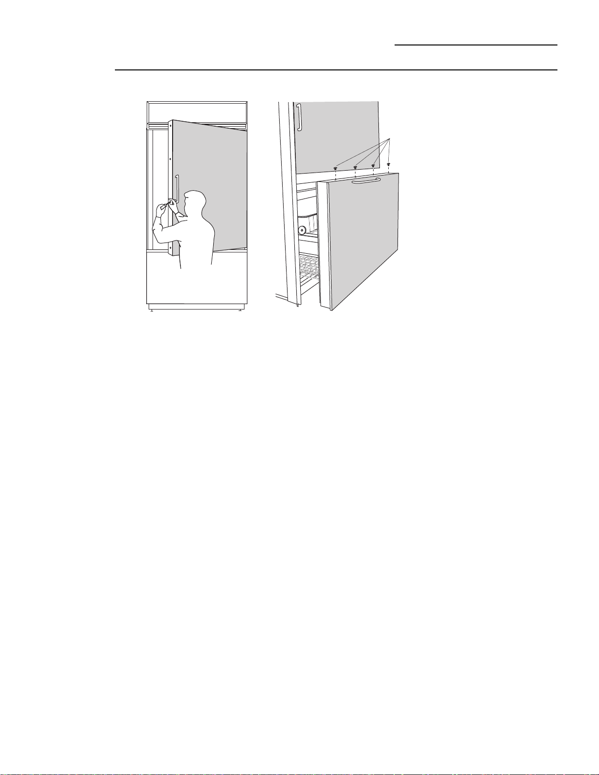
Step 4
Install
Assembled
Panels
It is best that 2 people perform this step.
Fresh Food Panel:
• Place assembled panel onto the bottom door trim
with support bracket tabs inserted into slots.
• Push and hold the panel back against the steel door
with door handle extrustion flush to the handle side
of the door.
• Reinstall original screws into the door extrusion.
• Open the door fully to stop.
• Install screws at the top, and hinge side.
Note: The freezer drawer panel should be removed
as shown in the installation instructions for the
ZKTC36 kit. Follow the instructions in Step 1 to
remove the door.
Freezer Drawer Panel:
• Place the assembled panel onto the bottom trim
with support brackets inserted into slots. The panel
should be flush with trim on both sides.
• Secure the panel to the trim at the bottom and both
sides.
• Mount the assembled drawer panel onto the freezer
slides. Tighten all screws.
• Install 4 screws into the top of the handle extrusion
and into the door.
Install
4 Screws
39
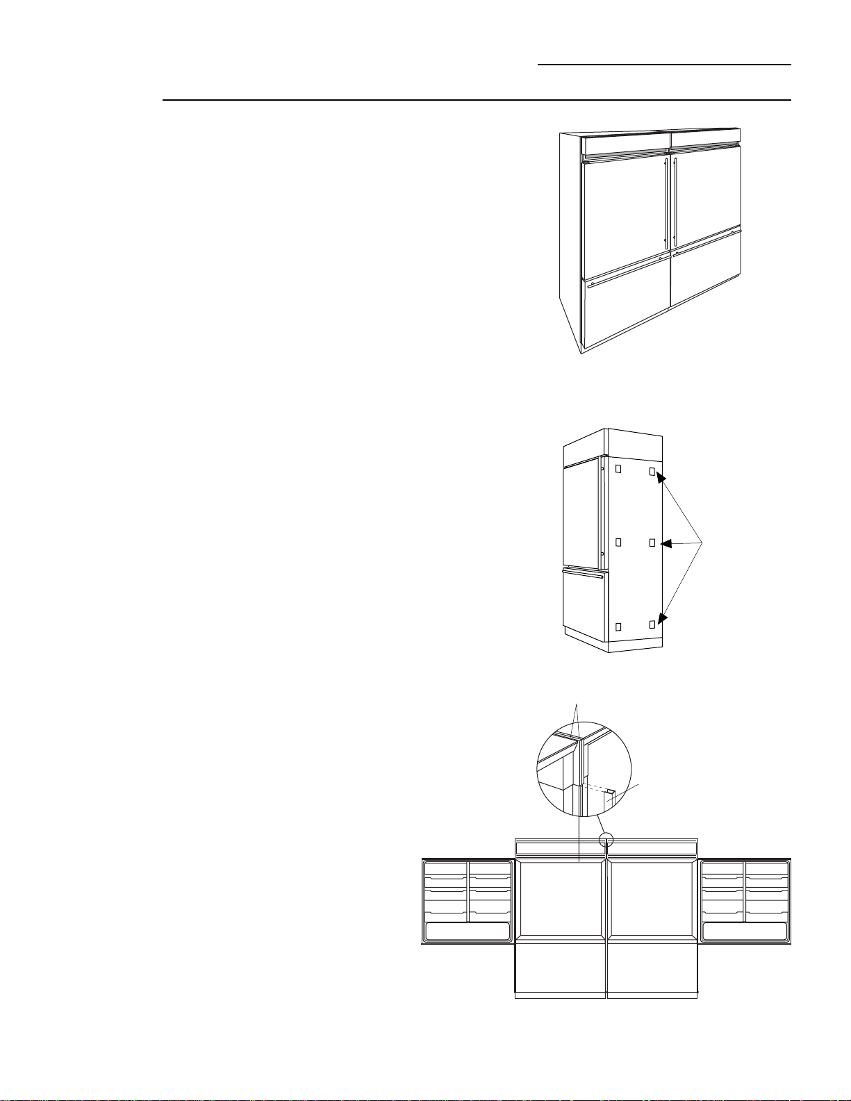
ZFC1 Trim Kit
Side to Side Installation
For the ultimate in convenience, install two refrigerators
side to side.
This trim kit includes 6 foam spacer pads to fill the gap
between the refrigerator side case trims. For a finished
appearance, a trim strip is provided to conceal the case
trim of the two refrigerators.
If you are installing into an enclosure, provide a 72" wide
opening. If you are installing where the sides of the
refrigerators will be exposed, allow additional width for
any side panels used.
• Apply foam spacer pads evenly to the side of one
refrigerator as shown.
• Slide second refrigerator into position.
• Check to be sure both refrigerators are level. If they
are not level, an obvious gap can be seen between
the side trims. Adjust leveling legs if needed. Slight
gaps will be concealed with the trim strip.
• Open both fresh food doors to access side trim.
• The U-shape trim will overlap the side case trim of
both refrigerators.
• Set the top case trim (see page 17) to installation
height.
• Hold trim strip against top end of case, at the point
where case overlaps to the bottom of case trim. See
illustration.
• Mark length with a pencil.
• Trim excess length.
• Starting at the top, press trim strip over case trims of
both refrigerators.
• Continue pressing about half way down. Slide open
freezer drawers and continue pressing trim until you
reach the bottom of the strip.
Foam
Spacer
Pads
Case Trim
U-Shape
Trim

Note: While performing installations described in this book,
safety glasses or goggles should be worn.
To obtain specific information concerning any
Monogram product or service, call GE Answer Center
®
consumer information service at 800.626.2000–any
time, day or night.
For Monogram
TM
local service in your area, call
1-800-444-1845.
Note: Product improvement is a continuing endeavor at
General Electric. Therefore, materials, appearance and
specifications are subject to change without notice.
Pub. No. 49-600000
1998 GE Appliances
Printed in U.S.A. (ND 978A) 8/98
5A 95020-00
Monogram.
®
General Electric Company
Louisville, KY 40225
