ZKHSS2
Tubular Stainless Steel Handles
Installation
Instructions
Right hand door swing models are illustrated in these
instructions. Follow these same instructions for left hand
models.
This kit provides for the installation of Tubular Stainless Steel
handles on 3/4” overlay custom panels.
Tools and materials Required:
• #2 Phillips screwdrivers
• Drill and 7/32” bit and 7/8” spade bit
• Custom door panels
• Safety glasses
• Center punch
• Hammer
• Pencil
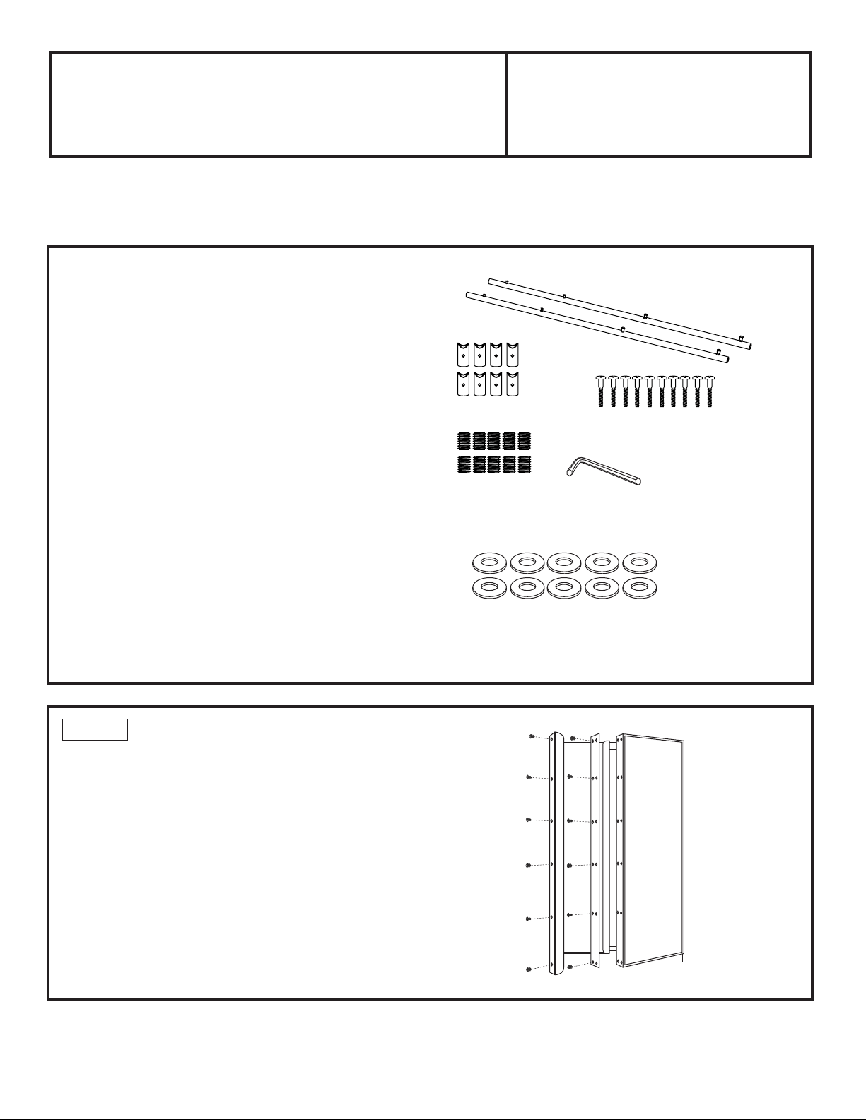
Parts List:
A. 2 Stainless tubular handles
B. 8 Handle standoffs
C. 10 Screws for handle standoffs
#10-32x1" pan head machine screws (8 required, 2 extra)
D. 10 Set screws (8 required, 2 extra)
E. 3/32” Allen wrench for set screws
F. 10 Plastic spacers (8 required, 2 extra)
Before you begin—Read these instructions completely and carefully.
Note to Installer: Be sure to leave these instructions with the consumer.
Note to Consumer: Keep these instructions with your Owner’s Manual for future reference.
Note to Consumer: If installing these handles on an All Refrigerator/All Freezer unit, only one handle is required.
F
STEP 1 REMOVE DOOR HANDLES
• Open refrigerator door to 90°. Remove the 6 screws
holding the handle to the door.
• Remove 6 screws holding handle side trim.
• For Side by Side models, retain all screws and trim.
Discard handles.
• For All Refrigerator/All Freezer models, retain all screws.
Discard trim and handles.
• Follow the same procedure to remove freezer handle
and trim.
B
C
E
D
A

2
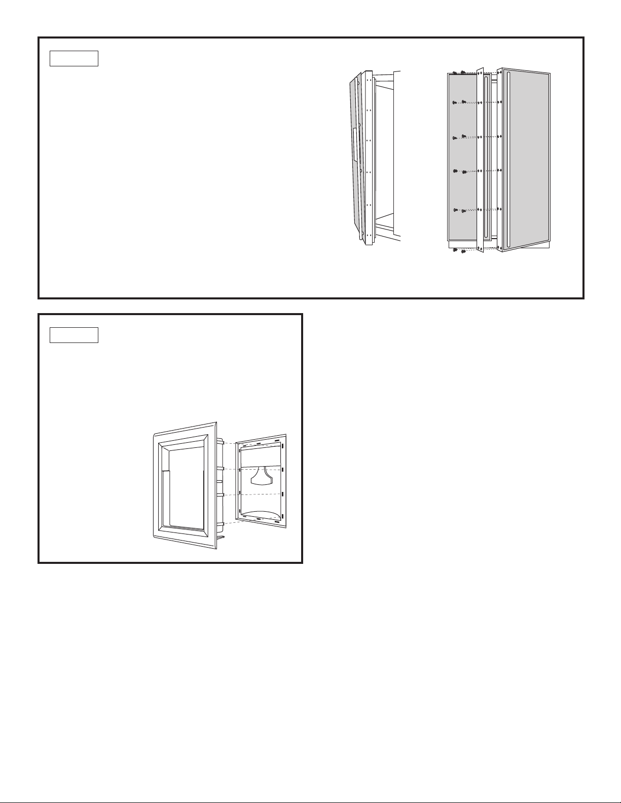
STEP 2 INSTALL HANDLES ONTO PANELS
Drill Pilot Holes
• Measure, mark and draw a line, 1-1/8" from the handle
side edge, top to bottom.
• Hold the tubular handle against the appearance side,
centered top to bottom and on the marked line.
• Mark the screw hole locations at the center of
the handle attachment posts. Place handle over
the marks to check again that holes are align
to handle posts.
• Center punch to mark hole locations. Drill 7/32" pilot
holes from the appearance side and through the entire
panel thickness.
• Follow the same procedure to drill pilot holes on the
opposite door for side by side panels.
Assemble Handles
• Place a handle standoff on each attachment post on the
handle. Position the screw hole on the standoff to point
to the floor.
• Install set screws into the bottom of each standoff, using
the Allen wrench provided. The standoff should be tight
against the handle.
Secure Handles to Panels
• Use a 7/8" spade bit to drill 1/2" to 9/16" max. depth
into the back side of the panel. At this depth there will
be enough screw threads to engage the handle
on the appearance side. See illustration.
• Stand the panel up on the hinge side. Place a plastic
spacer into the 7/8" opening, drop screw through
the spacer.
• Place handle standoffs against the mounting screws
on the appearance side, drive top screw partially
into the standoff.
• Drive next screw partially into the standoff. Continue
installing screws to the bottom location. Alternate back
to the top tightening screws one at a time until
the handle is tight against the panel.
CAUTION: Hole locations must be exact to accept
handle standoff and handle assembly.
Freezer
Panel
Fresh
Food
Panel
Screw
Allen Wrench
Attachment Post
7/8"
1/2" Min.
9/16" Max.
1.100"
3/4"
7/32"
Plastic
Spacer
Countersink screw
into panel as shown.
1-1/8”
1-1/8”
H
a
n
d
l
e
S
i
d
e
Side by Side Panels
All Refrigerator/
All Freezer Panels
H
i
n
g
e
S
i
d
e
3
STEP 3 INSTALL ASSEMBLED HANDLES
• Slide assembled panels into the door trim.
• Secure both trims using all original screws
(Side by Side models only).
• Secure new handle side trim that comes with your
unit using original screws (All Refrigerator/All Freezer
models only).
Dispenser Models Only:
• The dispenser controls protrude beyond the face
of the freezer door. To avoid damage to the dispenser,
the trim at the top of the door should be removed.
• Remove the screws holding the top trim in place.
Lift off trim.
• Place the freezer panel into the bottom channel
and slide into the hinge side trim.
• Reinstall the top trim piece with screws.
STEP 4 INSTALL DISPENSER TRIM
For dispenser models only.
There are two dispenser trims shipped with your
dispenser refrigerator. Note that the inside depth
of the frames are different. Choose the trim marked 3/4"
overlay panels.
• Press and snap
the dispenser trim
into the dispenser
recess on the door.
Dispenser
Trim
Side by side unit shown
Reinstall all original screws

31-46528
224D1889P013
09-08 JR
NOTE: While performing installations described in this book,
safety glasses or goggles should be worn.
NOTE: Product improvement is a continuing endeavor
at General Electric. Therefore, materials, appearance
and specifications are subject to change without notice.
GE Consumer & Industrial
Appliances
General Electric Company
Louisville, KY 40225
ge.com
NOTA: Mientras efectúa las instalaciones descriptas
en este libro, deben utilizarse gafas o lentes de seguridad.
NOTA: La mejora de los productos es un esfuerzo continuo
para General Electric. Por lo tanto, los materiales,
la apariencia y las especificaciones pueden sufrir cambios
sin previo aviso.