Loading ...
Loading ...
Loading ...
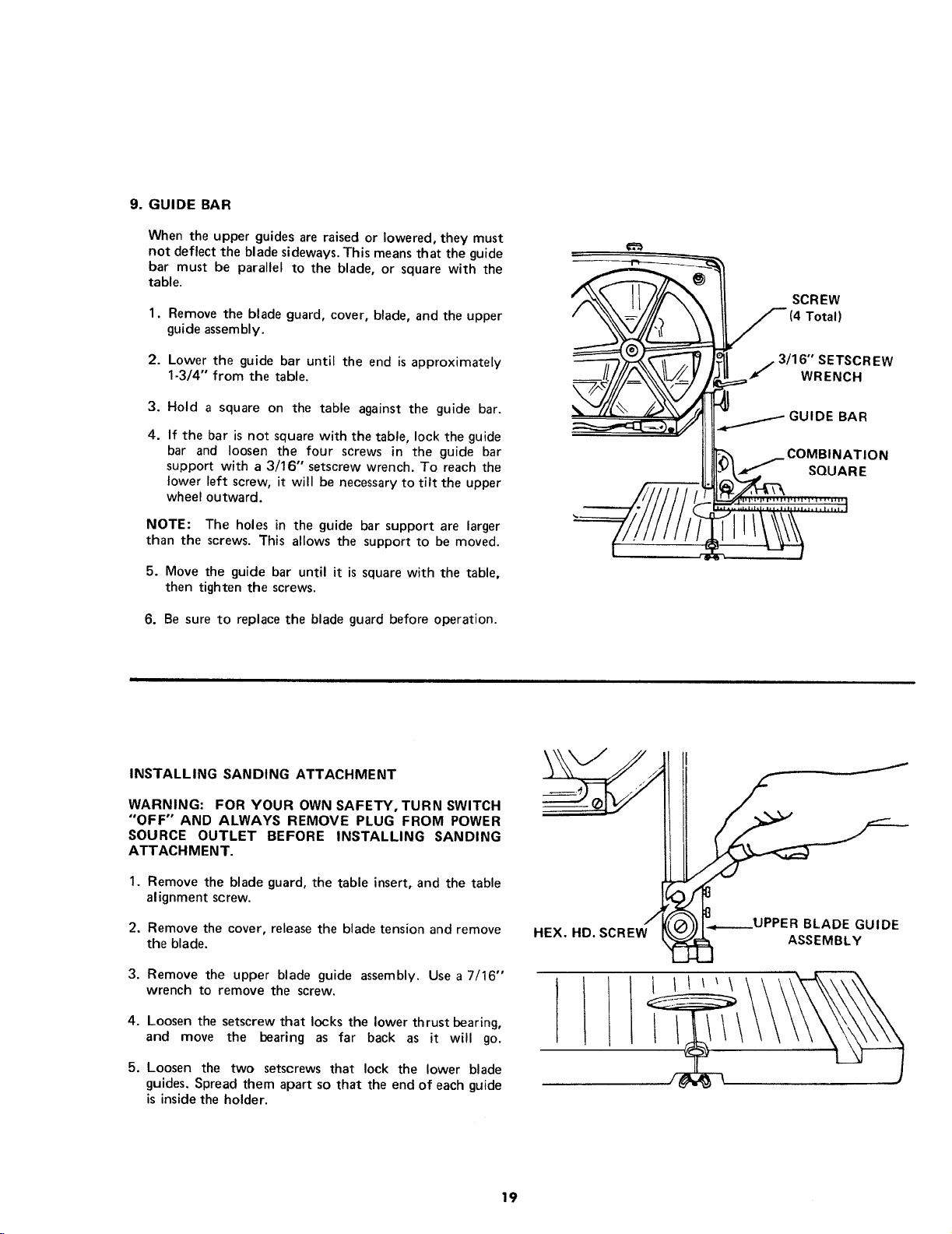
9.GUIDEBAR
When the upper guides are raised or lowered, they must
not deflect the blade sideways. This means that the guide
bar must be parallel to the blade, or square with the
table.
1. Remove the blade guard, cover, blade, and the upper
guide assembly.
2. Lower the guide bar until the end is approximately
1-3/4" from the table.
3.
4.
Hold a square on the table against the guide bar.
If the bar is not square with the table, lock the guide
bar and loosen the four screws in the guide bar
support with a 3/16" setscrew wrench. To reach the
lower left screw, it will be necessary to tilt the upper
wheel outward.
NOTE: The holes in the guide bar support are larger
than the screws. This allows the support to be moved.
5. Move the guide bar until it is square with the table,
then tighten the screws.
6. Be sure to replace the blade guard before operation.
=------_-_-_-_____=
__ SCREW
(4 Total)
_¢"_"_'_ _°il ,3/16" SETSCREW
J- W.ENCH
GU,OEBAR
INSTALLING SANDING ATTACHMENT
WARNING: FOR YOUR OWN SAFETY, TURN SWITCH
"OFF" AND ALWAYS REMOVE PLUG FROM POWER
SOURCE OUTLET BEFORE INSTALLING SANDING
ATTACHMENT.
1. Remove the blade guard, the table insert, and the table
alignment screw.
2. Remove the cover, release the blade tension and remove
the blade.
3. Remove the upper blade guide assembly. Use a 7/16"
wrench to remove the screw.
4. Loosen the setscrew that locks the lower thrust bearing,
and move the bearing as far back as it will go.
5. Loosen the two setscrews that lock the lower blade
guides. Spread them apart so that the end of each guide
is inside the holder.
\ II
HEX. HD. SCREW_K((_))I"_---UPPER BLADE GUIDE
ASSEMBLY
19
Loading ...
Loading ...
Loading ...