Loading ...
Loading ...
Loading ...
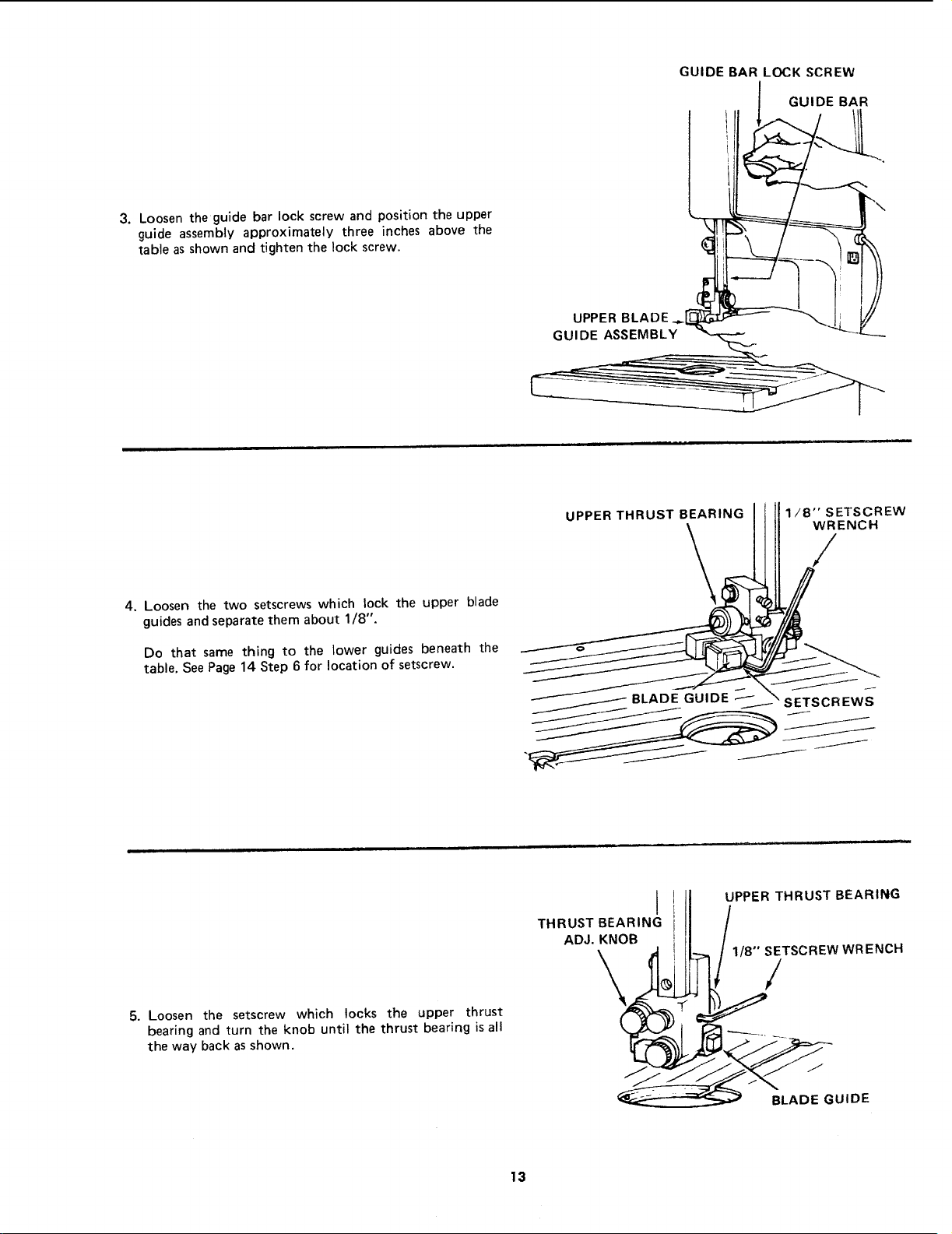
3. Loosen the guide bar lock screw and position the upper
guide assembly approximately three inches above the
table as shown and tighten the lock screw.
GUIDE BAR LOCK SCREW
GUIDE BAR
4. Loosen the two setscrews which lock the upper blade
guides and separate them about 1/8".
Do that same thing to the lower guides beneath the
table. See Page 14 Step 6 for location of setscrew.
UPPER THRUST BEARING I I II1/8"SETSCREW
_'_ _ _--" _SCREWS
5. Loosen the setscrew which locks the upper thrust
bearing and turn the knob until the thrust bearing is all
the way back as shown.
I II UPPER THRUST BEARING
II /
ADJ. KNOB i i] /
\ /_ _ [-_ /1/8" SETSCREW WRENCH
/
13
Loading ...
Loading ...
Loading ...