Loading ...
Loading ...
Loading ...
SERVICE AND ADJUSTMENT
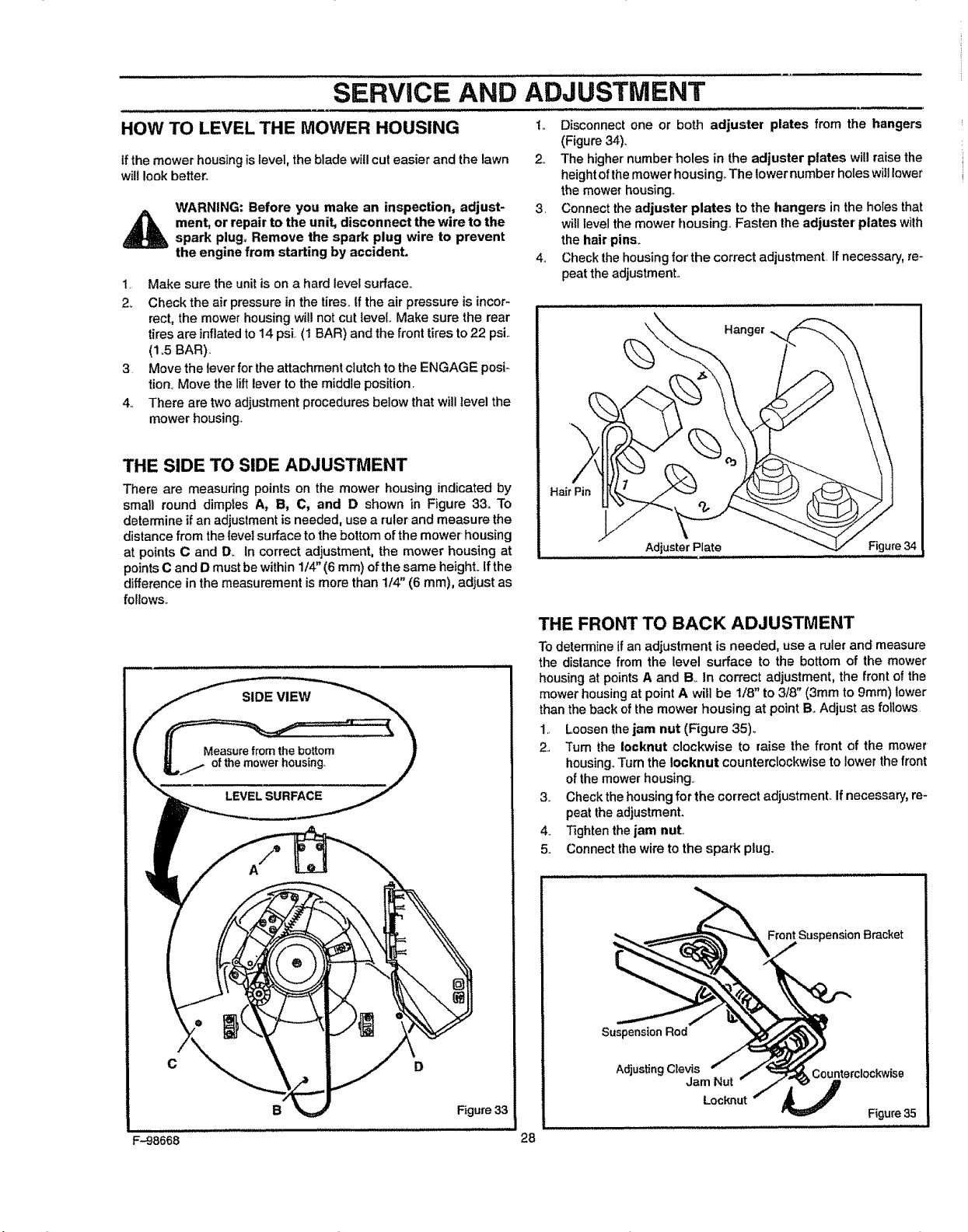
HOW TO LEVEL THE MOWER HOUSING t,. Disconnect one or both adjuster plates from the hangers
(Figure 34).
if the mower housing islevel, the blade will cut easier and the lawn
will look better°
WARNING: Before you make an inspection, adjust-
_ ment, or repair to the unit, disconnect the wire to the
spark plug+ Remove the spark plug wire to prevent
the engine from starting by accident.
1. Make sure the unitis on a hard level surface..
2+ Check the air pressure in the tires, tf the air pressure is incor-
rect, the mower housing willnot cut level.. Make sure the rear
tires are inflatedto 14 psi (1 BAR) and the front tires to 22 psi..
(1+5BAR).
3. Move the leverfor the attachment clutchto the ENGAGE posi+
lion+ Move the lift lever tothe middle position.
4.. There are two adjustment procedures below that willlevel the
mower housing..
2.. The higher' number holes in the adjuster plates will raisethe
height of the mower housing,. The lowernumberholes will lower
the mower housing+
3. Connect the adjuster plates to the hangers in the holes that
will level the mower housing. Fasten the adjuster' plates wilh
the hair pins.
4+ Check the housing for'the correct adjustment. If necessary, re-
peat the adjustmenL
THE SIDE TO SIDE ADJUSTMENT
There are measuring points on the mower housing indicated by
small round dimples A, B, C, and D shown in Figure 33. To
determine if an adjustment is needed, use a ruler and measure the
distance from the level surface to the bottom of the mower' housing
at points C and D+ In correct adjustment, the mower housing at
points C and D must be within 1/4' (6 ram) of the same height, tfthe
difference in the measurement is more than 1/4" (6 mm), adjust as
follows.+
C D
B Figure 33
Hanger
Hal
Adjuster Plate Figure 34
THE FRONT TO BACK ADJUSTMENT
To determineif an adjustment isneeded, use a ruler and measure
the dislance from the level surface to the bottom of the mower
housingat pointsA and B,+in correct adjustment, the front ofthe
mowerhousingat pointA will be 1/8" to 3/8" (3mm to 9mm) lower
than theback ofthe mower housing at point B. Adjust as follows.
1.. Loosenthejam nut (Figure 35)+
2, +rum the Iocknut clockwise to raise the front of the mower
housing.,+rumthe !ocknut counterclockwise tolower the front
ofthe mower housing.,
3., Check thehousingfor the correct adjustment,. Ifnecessary,re-
peat the adjustment.
4+ Tightenthe jam nut,,
5. Connect the wire tothe spark plug.
Suspension Bracket
Suspension Rod
Adjusting Clevis Counterclockwise
Jam Nut
Locknut
Figure 35
F-98668 28
Loading ...
Loading ...
Loading ...