End Panel Replacement
To prevent possible SERIOUS INJURY or DEATH:
• Disconnect ALL electric and battery power BEFORE performing
ANY service or maintenance.
To prevent damage to the receiver/logic board, DO NOT touch printed
circuit board of replacement receiver/logic board during installation.
ALWAYS wear protective gloves and eye protection when changing
the battery or working around the battery compartment.
A
B
D
C
E
F
WARNING t
AVER
TISSEMENT
WARNING: To avoid SERIOUS
PERSONAL INJURY or DEATH
from electrocution, disconnect
ALL electric and battery power
BEFORE performing ANY
maintenance.
AVERTISSEMENT: Pour éviter
des BLESSURES GRAVES ou la
MORT par électrocution,
débrancher l’alimentation
électrique et de batterie AVANT
TOUTE intervention de
maintenance.
PA
RT
NUMBER:
SERIAL NUMBER
DATE:
132B2759-5
MAC ADDRESS
IC: 2666A -
FCC ID:
To connect to a Wi-Fi Network, visit
wifihelp.chamberlain.com for more
details. You will need your "MyQ Serial
Number
" to complete setup.
100W Max26W
Max
THE CHAMBERLAIN GROUP INC.
ELMHURST IL, 60126, USA
Assembled in Mexico
CONTAINS:
FCC ID: COFWMNBM11
IC: 10239A-WMNBM11
Pour vous connecter à un réseau Wi-Fi,
visitez wifihelp.chamberlain.com pour
plusde détails. Vous aurez besoin de votre
« Numéro de Série MyQ » pour
compléter l’installation.
NETWORK SETUP CODE
Red
White
White
Grey
Receiver
Logic
Board
Receiver
Logic
Board
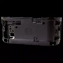
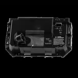
End
Panel
Antenna
wires
End
Panel
Wire
Harnesses
Light Socket Wires
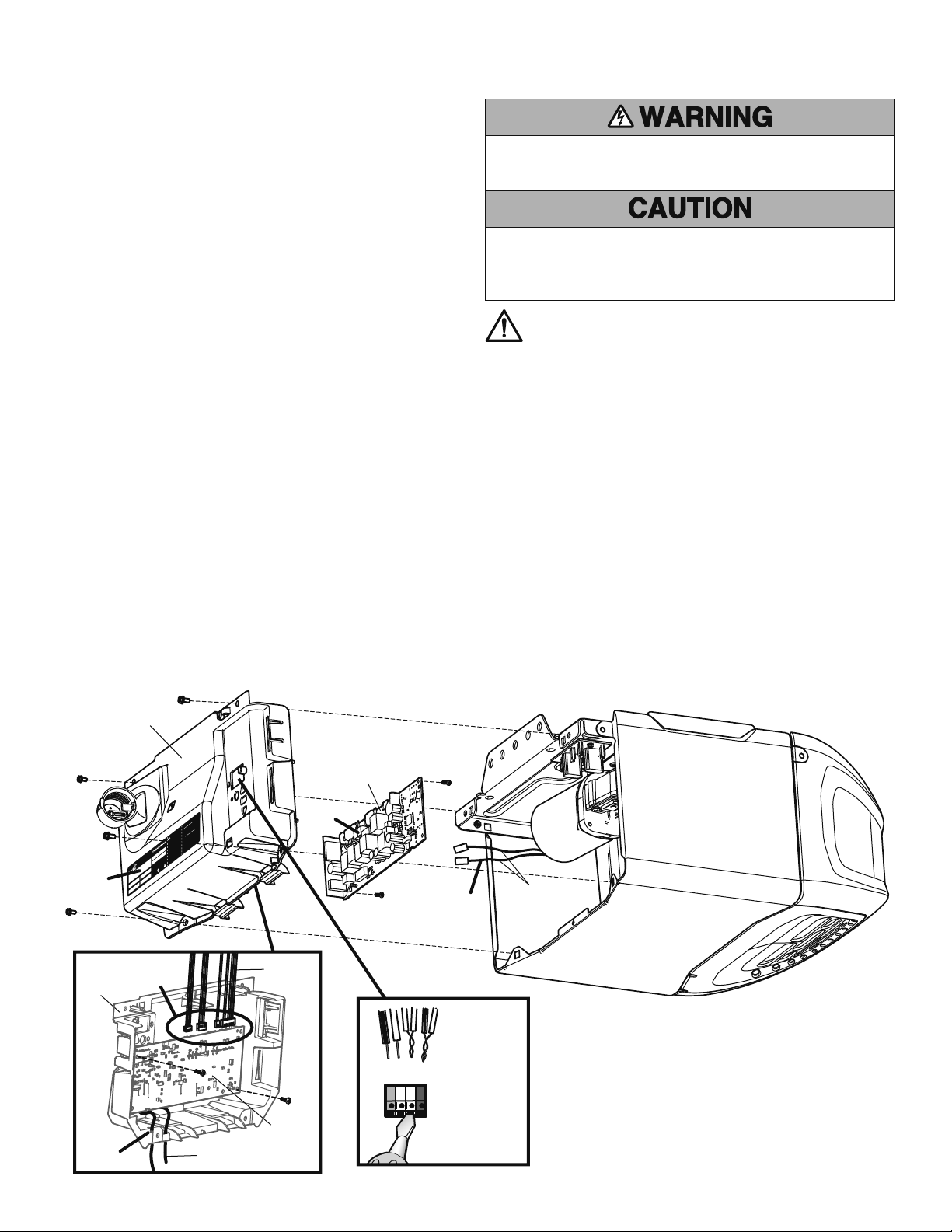
To insert or remove
the wires from the
terminal, push in
the tab with a
screwdriver tip.
Installation
NOTE: The products illustrated in the instructions are for reference. Your
product may look different.
1. Disconnect electrical and battery power (if applicable) to the garage
door opener.
2. Remove the light lens.
• To remove the lens press the release tabs on both sides of lens.
Gently rotate lens back and downward until the lens hinge is in the
fully open position. Lift lens up slightly and remove.
OR
• Press the release tabs on both side of the lens. Squeeze the light
lens clips to remove lens from end panel.
OR
• Remove the light lens by pulling the top sides of the light lens and
rotate the light lens down. Squeeze the light lens clips to remove
lens from end panel.
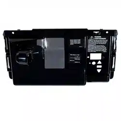
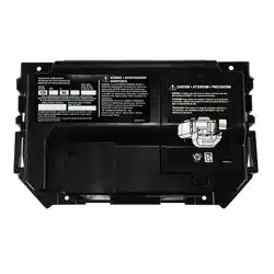
3. Disconnect the wires (A).
4. Remove the end panel.
• Unplug the wire harnesses from the receiver logic board (B).
• Remove the receiver logic board (C).
• Remove antenna wires from holes in the old end panel (D).
• Unplug the wires for the light socket (E).
5. A blank label has been provided with your replacement end panel.
Copy the MyQ
®
Serial Number and all other information from the
original end panel label to the new label. This information is needed
when connecting your garage door opener to the Internet. Apply new
label to replacement end panel (F).
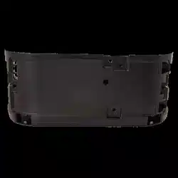
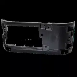
6. Discard old end panel.
7. Install the new end panel.
• Connect the wire harnesses to the receiver logic board (B).
• Reinstall the receiver logic board (C).
• Insert the antenna wires through the holes in the end panel (D).
• Connect the wires to the light socket (E ).
• Attach the end panel.
8. Reinsert the wires (A).
Door control wires: • white wire into the white terminal.
• white/red wire into the red terminal.
Safety sensor wires: • white wires into the white terminal.
• white/black wires into the grey terminal.
9. Attach the light lens. Make sure the antenna wires are hanging
straight down.
10. Reconnect power to the garage door opener.
11. Test of the safety reverse system. Refer to the owner’s manual.
WARNING: This product can expose you to chemicals including
lead, which are known to the State of California to cause cancer
or birth defects or other reproductive harm. For more information
go to www.P65Warnings.ca.gov

Pour prévenir d’éventuelles BLESSURES GRAVES ou LA MORT:
• Débrancher l'alimentation batterie et l'alimentation secteur AVANT
TOUTE réparation ou maintenance.
Pour empêcher tout dommage à la carte logique du récepteur, NE
touchez PAS au circuit imprimé de la carte logique du récepteur de
remplacement durant l’installation.
Munissez-vous TOUJOURS de gants de protection et de protection
pour les yeux quand vous travaillez sur une pile électrique ou sur un
compartiment de batterie.
Remplacement du panneau d'extrémité
A
B
D
C
E
F
WARNING
t
AVERTISSEMENT
WARNING: To avoid SERIOUS
PERSONAL INJURY or DEATH
from electrocution, disconnect
ALL electric and battery power
BEFORE performing ANY
maintenance.
AVERTISSEMENT: Pour éviter
des BLESSURES GRAVES ou la
MORT par électrocution,
débrancher l’alimentation
électrique et de batterie AVANT
TOUTE intervention de
maintenance.
PART
NUMBER:
SERIAL NUMBER
DATE:
132B2759-5
MAC ADDRESS
IC: 2666A -
FCC ID:
To connect to a Wi-Fi Network, visit
wifihelp.chamberlain.com for more
details. You will need your "MyQ Serial
Number
" to complete setup.
100W Max26W
Max
THE CHAMBERLAIN GROUP INC.
ELMHURST IL, 60126, USA
Assembled in Mexico
CONTAINS:
FCC ID: COFWMNBM11
IC: 10239A-WMNBM11
Pour vous connecter à un réseau Wi-Fi,
visitez wifihelp.chamberlain.com pour
plusde détails. Vous aurez besoin de votre
« Numéro de Série MyQ » pour
compléter l’installation.
NETWORK SETUP CODE
Rouge
Blanc
Blanc
Gris
Pour relâcher ou
insérer le fil,
enfoncer la
languette à l’aide
de l’extrémité du
tournevis.
Fils
d’antenne
Fils de douille de
lampe d’éclairage
Panneau
d’extrémité
Panneau
d’extrémité
Harnais
de fil
Carte logique
du récepteur
Carte logique
du récepteur
Installation
REMARQUE : Les produits illustrés dans les instructions sont pour
référence. Votre produit peut toutefois avoir l’air différent.
1.
Déconnectez l’alimentation électrique et les piles (le cas échéant)
connectées à l’ouvre-porte de garage.
2. Retirez la lentille de la lampe.
• Démontez le diffuseur et appuyez sur les pattes de dégagement des
deux côtés du diffuseur. Faites pivoter le diffuseur délicatement
vers l’arrière et vers le bas jusqu’à ce que la charnière du diffuseur
soit complètement ouverte. Soulevez le diffuseur légèrement et
enlevez-le.
OU
• Appuyez sur les pattes de dégagement des deux côtés de la lentille.
Serrez les agrafes de la lentille pour la retirer du panneau
d'extrémité.
OU
• Retirez la lentille en tirant les côtés du haut de la lentille et en
tournant la lentille vers le bas. Serrez les attaches de la lentille pour
retirer la lentille du panneau d’extrémité.
3. Déconnectez les fi ls (A).
4. Retirez du panneau d’extrémité.
• Débranchez les harnais de fi ls de la carte logique du récepteur (B).
• Retirez la carte logique du récepteur (C).
• Enlever les fi ls de l’antenne des trous dans le panneau d’extrémité
usagé (D).
• Débranchez les fi ls de la douille (E).
5. Une étiquette vierge a été fournie avec le panneau d’extrémité de
rechange. Copier sur l’étiquette neuve le numéro de série MyQ
®
et
toute autre information figurant sur l’étiquette originale du panneau
d’extrémité. Cette information est nécessaire pour la connexion de
votre ouvre-porte de garage à Internet. Apposer l’étiquette neuve sur
le panneau d’extrémité de rechange (F).
6. Jetez l'ancien panneau d'extrémité.
7. Installer le panneau d’extrémité neuf.
• Connectez les harnais de fi ls à la carte logique du récepteur (B).
• Réinstaller la carte logique du récepteur (C).
• Insérez les fi ls d’antenne à travers les trous du panneau
d’extrémité. (D).
• Connecter les fils à la douille de la lampe d’éclairage (E).
• Fixez du panneau d’extrémité.
8. Réinsérez les fi ls (A).
Fils de commande • fi l blanc sur la borne blanche.
de la porte : • fi l blanc/rouge sur la borne rouge.
Fils de détecteur-inverseur • fi ls blancs sur la borne blanche.
de sécurité : • fi ls blanc/noir sur la borne grise
du panneau d’extrémité.
9. Fixez la lentille de la lampe. S’assurer que les fils de l’antenne pendent
tout droit.
10. Remettre l'ouvre-porte de garage sous tension.
11. Tester le système d’inversion de sécurité. Se reporter au guide de
propriétaire.
AVERTISSEMENT : Ce produit peut vous exposer à des produits
chimiques comme le plomb, reconnu par l’État de la Californie
comme cause de cancers, d’anomalies congénitales et d’autres
problèmes liés à la reproduction. Pour plus d’informations, visitez
www.P65Warnings.ca.gov

Para evitar la posibilidad de LESIONES GRAVES o INCLUSO LA MUERTE:
• Desconecte TODA la corriente eléctrica y de la batería ANTES de realizar
cualquier servicio o mantenimiento.
Para evitar que se dañe la tarjeta lógica/el receptor, NO toque la tarjeta
de circuito impresa de la tarjeta lógica/del receptor de reemplazo
durante la instalación.
SIEMPRE uso los guantes protectores y protección ocular cuando
cambiar la batería o trabajando cerca el compartimiento de la batería.
Cambio del panel terminal
A
B
D
C
E
F
WARNING
t
AVERTISSEMENT
WARNING: To avoid SERIOUS
PERSONAL INJURY or DEATH
from electrocution, disconnect
ALL electric and battery power
BEFORE performing ANY
maintenance.
AVERTISSEMENT: Pour éviter
des BLESSURES GRAVES ou la
MORT par électrocution,
débrancher l’alimentation
électrique et de batterie AVANT
TOUTE intervention de
maintenance.
PART
NUMBER:
SERIAL NUMBER
DATE:
132B2759-5
MAC ADDRESS
IC: 2666A -
FCC ID:
To connect to a Wi-Fi Network, visit
wifihelp.chamberlain.com for more
details. You will need your "MyQ Serial
Number
" to complete setup.
100W Max26W
Max
THE CHAMBERLAIN GROUP INC.
ELMHURST IL, 60126, USA
Assembled in Mexico
CONTAINS:
FCC ID: COFWMNBM11
IC: 10239A-WMNBM11
Pour vous connecter à un réseau Wi-Fi,
visitez wifihelp.chamberlain.com pour
plusde détails. Vous aurez besoin de votre
« Numéro de Série MyQ » pour
compléter l’installation.
NETWORK SETUP CODE
Rojo
Blanco
Blanco
Gris
Para insertir o soltar
el cable, empuje la
lengüeta hacia
dentro con la punta
de un destornillador
Cables de
la antena
Cables del receptáculo
de luz
Panel de
extremo
Panel de
extremo
Arnés del
cable
Tarjeta lógica
del receptor
Tarjeta lógica
del receptor
Instalación
NOTA: Los productos ilustrados en las instrucciones son para su
referencia. Su producto puede verse diferente.
1. Desconecte del abre-puertas de garaje la alimentación eléctrica y la
batería (si estuviera usando una).
2. Quite la tapa de la luz.
• Quite la tapa óptica presionando las pestañas de ambos lados y
haciéndola girar hacia abajo hasta que quede colgando de la
bisagra en posición abierta. Levante la lente y quítela.
O
• Oprima las lengüetas de desenganche a ambos lados del tapa de la
luz. Apriete las abrazaderas de la tapa para extraerla del panel
terminal.
O
• Retire la lente de luz tirando de los lados superiores de la lente de
luz y rotando la lente de luz hacia abajo. Ajuste los precintos de la
lente de luz para retirar la lente del panel posterior.
3. Desconecte los cables (A).
4. Retire del panel posterior.
• Desenchufe los hatos de cable de la tarjeta lógica del receptor (B).
• Retire la tarjeta lógica del receptor (C).
• Quitar los conductores de la antena de los orifi cios en el panel
original (D).
• Desenchufe los cables del receptáculo de luz (E).
5. El panel de repuesto se suministra con una etiqueta en blanco.
Escriba en ella el número de serie MyQ
®
y los otros datos presentes
en la etiqueta del panel original. Esta información se utilizará para
conectar el abre-puerta de garaje a Internet. Colocar la nueva etiqueta
en el panel nuevo (F).
6. Deseche el panel usado.
7. Instalar el panel nuevo.
• Conecte el hato de cables a la tarjeta lógica del receptor (B).
• Volver a instalar la tarjeta lógica del receptor (C).
• Inserte los cables de la antena a través de los orifi cios del panel
posterior (D).
• Conectar los cables al receptáculo de luz (E).
• Coloque del panel posterior.
8. Vuelva a insertar los cables (A).
Cables de control • el cable blanco en el terminal blanco.
de la puerta: • el cable blanco/rojo en el terminal rojo.
Cables de los sensores • los cables blancos en el terminal de
seguridad: blanco. • los cables blancos/negros en el
terminal gris.
9. Coloque la tapa de la luz. Verificar que los conductores de la antena
queden colgando hacia abajo.
10. Conectar la alimentación eléctrica al abre-puerta.
11. Probar el sistema de inversión de marcha. Consultar el manual de
instrucciones.
ADVERTENCIA: Este producto puede exponerle a productos
químicos (incluido el plomo), que a consideración del
estado de California causan cáncer, defectos congénitos u
otros daños reproductivos. Para más información, visite
www.P65Warnings.ca.gov

© 2015, LiftMaster
All rights reserved
Tous droits réservés
114A4834B Todos los derechos reservados