
Loading ...
Loading ...
Loading ...
EN
W415-2349 / A / 10.31.19
25
installation
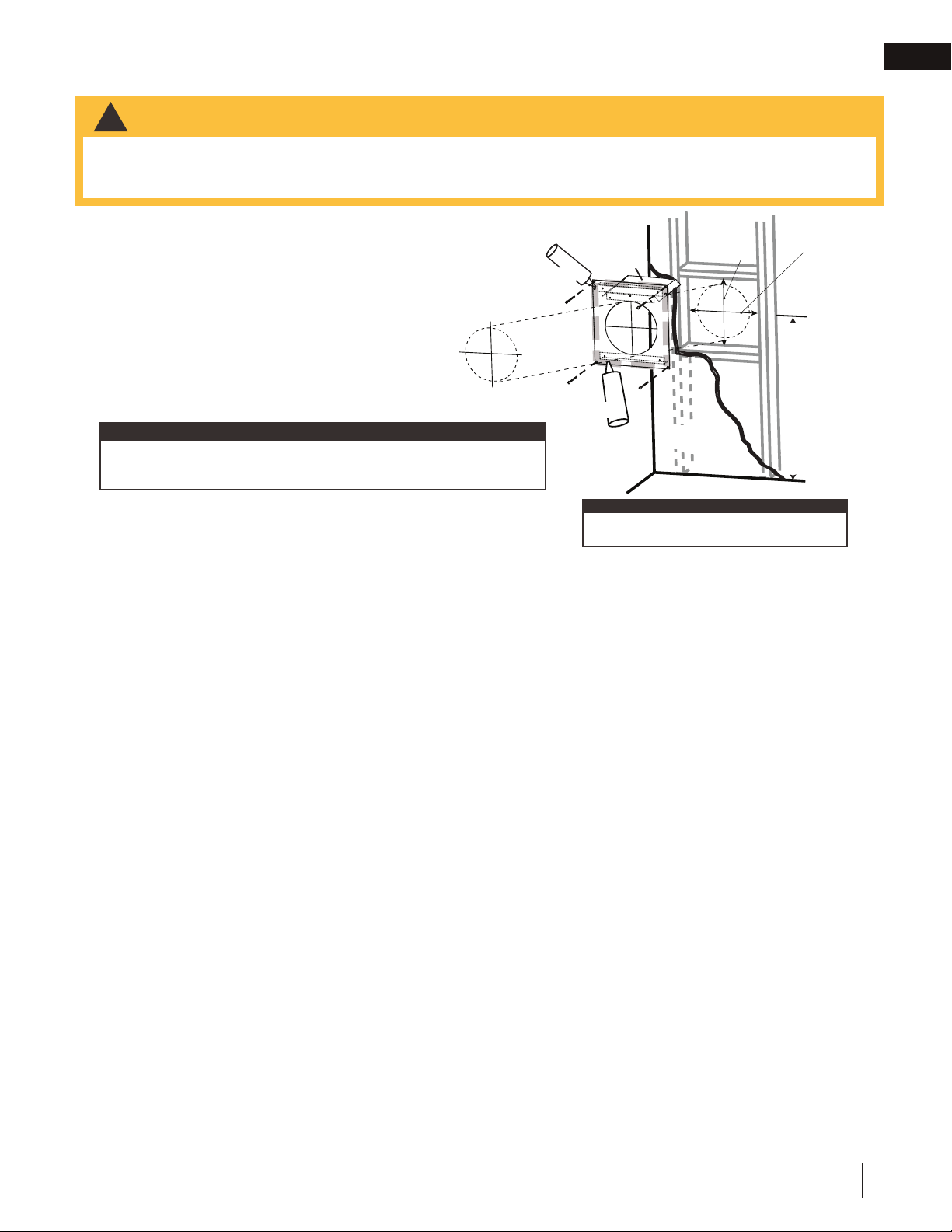
4.1.1 horizontal installation
This application occurs when venting through an exterior
wall. Having determined the correct height for the air
terminal location, cut and frame a hole in the exterior wall,
as illustrated, to accommodate the fi restop assembly. Dry
fi t the fi restop assembly before proceeding to ensure the
brackets on the rear surface fi t to the inside surface of the
horizontal framing.
The length of the vent shield may be cut shorter for
combustible walls that are less than 8 1/2” (215.9mm)
thick but the vent shield must extend the full depth of the
combustible wall.
A. Apply a bead of caulking (not supplied) around the outer edge of
the hole of the fi restop assembly, fi t the fi restop assembly to the
hole and secure using 4 screws.
B. Once the vent pipe is installed in its fi nal position, apply red RTV silicone (W573-0002) (not supplied)
between the pipe and the fi restop.
• The fi restop assembly must be installed with the vent shield to the top.
• Terminals must not be recessed into a wall or siding more than the depth of the return fl ange of the mounting
plate.
!
WARNING
Do not fi ll the air space between the fi restop spacer and the
exterior wall with any type of insulating material (i.e. spray foam).
note:
DETERMINE
THE
CORRECT
HEIGHT
CAULKING
FIRESTOP
SPACER
VENT
SHIELD
FINISHING
MATERIAL
CAULKING
note:
The above is for illustration purposes only. Vents
do not always pass through center of frame.
ADD
WIDTH
ADD
HEIGHT
Loading ...
Loading ...
Loading ...