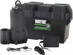
User Gudie Wayne ESP25 Battery Backup System
Description
- The ESP25 is a battery operated back-up sump pump. It does not replace a regular pump. It is designed to provide protection in the event household electrical power fails.
Unpacking
- Inspect this unit before it is used. Occasionally. products are damaged during shipment.
- If the pump or components are damaged. return the unit to the place of purchase for replacement. Failure to do so could result in serious injury or death.
Safety Guidelines
- This manual contains information that is very important to know and understand. This information is provided for SAFETY and to PREVENT EQUIPMENT PROBLEMS. To help recognize this information. observe the following symbols.
- Danger indicates an imminently
- Warning indicates a potentially
- Caution indicates a potentially
- Notice indicates important
- MAY cause damage to equipment.
- General Safety Information
- Do NOT use to pump
- If the basement has
- All wiring must be performed by a
- Do NOT expose battery to
- Battery acid is corrosive
- Avoid spilling on skin or clothing. Eye
- A check valve MUST be used on the
- A ground fault circuit interrupter
- This pump MUST only be used to pump
- The system is designed to operate most efficiently with sealed lead acid (SLA) batteries. Sealed lead acid batteries cost slightly more. but they can last longer. The oversize battery case (included) will accommodate a 12-volt SLA battery (up to a 27-frame size).
- Be certain that the area around the batteries is well ventilated. Before servicing the batteries. blow away gasses by waving a piece of cardboard near the batteries.
- Dangerous hydrogen gas CAN
Working in the vicinity of lead acid
- An assistant should be present or close enough to come to your aid in the event of an emergency. Have a reliable source of fresh water and soap nearby in case batttery acid contacts skin or eyes.
- Please read and save these instructions. Read carefully before attempting to assemble. install. operate or maintain the product described.
- Protect yourself and others by observing all safety information. Failure to comply with instructions could result in personal injury and/or property damage! Retain instructions for future reference.
REMINDER:
- Keep your dated proof of purchase for warranty purposes! Attach it to this manual or file it for safekeeping.
- Wear eye or clothing protection when working around lead acid batteries. Avoid touching your eyes when working around lead acid batteries.
If battery acid contacts your eye(s).
- NEVER smoke or allow a spark or
- Avoid dropping metal tools on the
1. Turn power to main pump off.
2. Pump must be instaled using 1 1/4" or 1 1/2" rigid PVC piping.
Pump Installation
- The back-up pump can be installed with a separate dedicated discharge line (Method 1). or tied into an existing sump pump line (Method 2).
- Unplug the existing AC pump. Failure
1. Verify that the existing AC pump is in good working order. If the AC pump is questionable. it is typically recommended that the unit be replaced with a 1/3 or 1/2 HP pump.
2. Remove any silt or accumulated debris from the sump pit and surrounding area.
Method 1 (Preferred)
- Locate the back-up pump on a solid. level surface in the sump pit. Do not place the pump on a loose or sandy surface. Small stones or sand may damage the pump resulting in potential pump failure.
- This pump has a 1 1/2" NPT discharge. If a 1 1/4" discharge pipe is desired. an adapter (not included) will be necessary. Smaller diameter piping will reduce pump flow. rate and performance.
- Cut a 4' section of 1 1/4" or 1 1/2" diameter rigid PVC pipe. Cement 1 1/4" pipe to a threaded fitting. Cement 1 1/4" pipe into pipe coupling. Attach 1 1/4" pipe section to the back-up pump discharge adapter.
- Screw on to pump discharge.
Be careful NOT to strip or cross
- Flex hose is NOT recommended. Rigid PVC or metal pipe is required for permanent installation.
- Operating Instructions and Parts Manual
- Place the pump with the 4' section of PVC pipe on a solid. level surface in the sump pit on an elevated surface.
- Attach a rubber check valve (sold separately) to the top of the discharge pipe. This will allow the pump or check valve to be removed easily for servicing.
NOTE:
- Check valves can be placed directly in the pump discharge if desired. However. for ease of disassembly. it is recommended that check valves be placed above the sump as shown in Figure 1.
- The remainder of the discharge pipe installation will vary depending on individual circumstances. Using sound plumbing practices. route the discharge pipe to an exterior wall by the shortest path. Keep turns to a minimum because they reduce flow output of the pump.
- The pipe that exits the building structure should be sloped downward so that water will not freeze in the pipe.
- When installing the separate discharge pipe. drill through the outside wall with appropriate drilling equipment. Seal the hole to prevent water from entering.
Floor Joist
- Rigid PVC Pipe
- Transformer
- Check Valve (See step 6)
- Battery Box
- Back-up Pump Existing Pump
- Slope Pipe Down
- PVC Pipe
- Float Switch
Method
If a separate. dedicated discharge is not possible as in Method 1. the back-up pump can be tied into the AC operated pump's discharge pipe by installing a "Y" connector. Two check valves will be required.
1. Locate the back-up pump on a solid. level surface in the sump pit. Do not place the pump on a loose or sandy surface. Small stones or sand may damage the pump resulting on potential pump failure.
2. This pump has a 1 1/2" NPT discharge. If a 1 1/4" discharge pipe is desired. an adapter (not included) will be necessary. Smaller piping will reduce pump flow. rate and performance.
3. A check valve will be required in the discharge line of BOTH the Main AC pump and the back-up pump to prevent recirculation of water into the sump pit.
System will not function without two check valves.
4. Cut a 4' section of 1 1/4" or 1 1/2" diameter rigid PVC pipe. Cement 1 1/4" pipe to a threaded fitting. Cement 1 1/4" pipe into pipe coupling. Attach 1 1/4" pipe section to the back-up pump discharge adapter.
5. Screw on to pump discharge.
- Be careful NOT to strip or cross
- Flex hose is NOT recommended. Rigid PVC or metal pipe is required for permanent installation.
6. Place the pump with the 4' section of PVC pipe on the sump floor or on an elevated surface if required.
7. Attach a rubber check valve (sold separately) to the top of the discharge pipe. This will allow the pump or check valve to be removed easily for servicing.
8. Duplicate the discharge piping arrangement for the primary AC pump if the discharge line has to be adjusted to accomodate a second pump.
9. Glue a 45º elbow to the short pipe on the back-up pump. Glue a "Y" adapter to the short pipe on the existing pump. as shown in illustration for Method 2.
10. Glue a short piece of PVC pipe between the 45º elbow and the "Y".
NOTE:
- Check valves can be placed directly in the pump discharge if desired. However. for ease of disassembly. it is recommended that check valves be placed above the sump as shown in Figure 2.
- The remainder of the discharge pipe installation will vary depending on individual circumstances. Using sound plumbing practices. route the discharge pipe to an exterior wall by the shortest distance.
Methods 1 and 2
- Install float switch at least 10"-12" above bottom of sump pit so that back-up unit turns on only when the water
- Floor Joist
- Rigid PVC Pipe
- Transformer
- Check Valve (See step 10)
- Battery Box
- Back-up Pump Existing Pump
- Slope Pipe Down
- Check Valve (See step 10)
- Figure 2 - Method 2
Connector
Control Box Installation
1. Place battery in box. attach red cable to positive battery post and black cable to negative battery post.
If cables are reversed. damage to the
2. Plug the float switch. pump and transformer into the appropriate connectors. The connections are all unique and cannot be interchanged.
3. Put lid on box. and place the battery within six feet of the sump and a 115 VAC separately fused outlet. The outlet must be protected by a ground fault circuit interrupter (GFCI) The area must also be clean. dry and well ventilated.
Float Switch
- Test pump operation by filling the sump with water while the main pump is unplugged. If the pump operates properly. plug the transformer into the GFCI protected outlet to begin charging the battery.
- Protect electrical cord from sharp objects. hot surfaces. oil and chemicals. Avoid kinking the cord and replace damaged components immediately.
Operation
- Always disconnect the power source
- Risk of electrical shock! Use
1. After installation. the back-up pump will start when the water level rises above the depth that the primary pump should start.
2. The control box has a DC charger designed to shorten the recharging time of your battery. and to prevent overcharging. In addition. the control box has a time delay which keeps the pump from repeated. short cycles when it shuts off. The time delay feature will allow the pump to run 20-25 seconds after the switch reaches the off position.
3. The control box contains multi-colored indicator lights. When AC power is present. the lights will indicate the charging state. and not reflect actual battery voltage. particularly with a defective battery. In order for the indicator light to provide an accurate reading. steps "a" through "d" must be followed.
- Unplug main AC pump and the
- Operating Instructions and Parts Manual
- Green: Indicates the battery is fully charged.
- Yellow: Indicates battery is partially charged. but still operable.
- Red: Battery is completely discharged or defective.
- Red blinking: Battery discharged below level where pumping can occur. Motor is locked out by controller until battery is sufficiently charged to run pump.
- When main AC power is out. and when pump has been running. the lights will indicate battery status.
4. A chirping sound from the control box will accompany the red light. indicating that the battery may require attention or replacement. Voltage is only an indicator of battery condition and may not reflect the true condition of the battery. See maintenance for instruction on assessing battery condition.
5. A single thirty (30) second tone will sound when power to the system is interrupted and the power failure light will illuminate. The unit will reset and the light will go out automatically when power is restored.
6. A three (3) second tone will sound every time the pump starts.
Maintenance
- Always disconnect the
- Once a month. check the battery
- Unplug the transformer.
- For batteries with top caps that can be removed. the electrolyte level should be checked and filled to manufacturer's specifications. The charge for each cell should be checked with a hydrometer. A gravity of 1.265 indicates the battery is at full charge. If the specific gravity of any of the cells varies more than 050. the battery should be replaced.
NOTE:
- An inexpensive hydrometer can be purchased at an automotive parts dealer.
- Inspect the terminals and clamps for corrosion and tightness. Clean and tighten as required.
- Unplug the main pump and fill sump with water until back-up pump turns on. Repeat process two times to make sure pump is operating normally.
Batteries
- Dangerous hydrogen gas CAN be
- Working in the vicinity of lead acid
- Never smoke or allow a spark or flame
- Avoid dropping metal tools on the
- Follow battery manufacturer's maintenace procedures and schedules. Be certain that the area around the batteries is well ventilated. Before servicing the batteries. blow away gasses by waving a piece of cardboard near the batteries.
Troubleshooting Chart
- Symptom Possible Cause(s) Corrective Action
- Pump won't run
- Connections not secure
- Low or defective battery
- Float switch stuck
1. Check all connections
2. Check battery and replace if low or defective
3. Make sure nothing is interfering with operation of switch
4. Defective or blown fuse
5. Battery voltage below threshold. motor locked out
4. Check internal fuse located inside the control box. Pull
5. Wait for battery to recharge or replace with fresh battery
Motor hums but won't run
- Defective battery 2. Impeller is locked
- Check battery and replace if low or defective 2. Unplug pump. remove screen. and check to see if
- Pump runs but pumps very little or no water
- Check valve missing or
- Check to make sure valves installed between primary
- Obstruction in discharge pipe 3. Discharge length and/or height
- Low or defective battery
- Check for obstruction and clear if necessary 3. If discharge is too high. a separate line may be required
- Check battery and replace if low or defective
Pump cyles too frequently
- Check valve problem
- Check to make sure valves installed between primary
- Power failure light is on but A/C power is available
- Transformer is bad
- Bad or no connection
- Branch circuit breaker/fuse
- Replace transformer
- Check that A/C plug and transformer connection at lid
- Reset breaker or replace fuse
- If battery acid contacts your eye(s).