Loading ...
Loading ...
Loading ...
9
NOTICE: The National
Fuel Gas Code (NFGC)
mandates a manual
gas shut-off valve: See
(NFGC) for complete
instructions. Local codes
or plumbing authority
requirements may vary
from the instructions or
diagrams provided and
take precedent over these
instructions.
A new combination temperature and pressure relief valve, complying with the Standard for Relief Valves
and Automatic Gas Shut-Off Devices for Hot Water Supply Systems, ANSI Z21.22 /CSA 4.4, is factory
installed and must remain in the opening provided and marked for the purpose on the water heater. No
valve of any type should be installed between the relief valve and the tank. Local codes shall govern the
installation of relief valves.
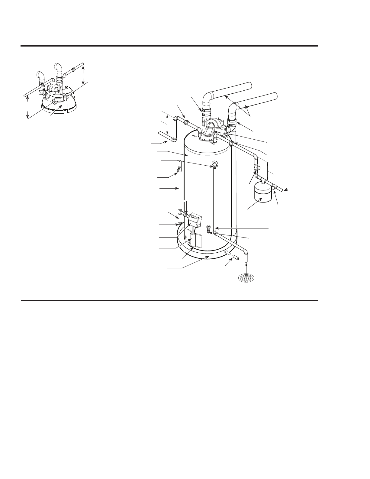
Typical Installation
Heat trap
6 in. (15.2 cm) min.
Heat trap
6 in. (15.2 cm) min.
Union (Optional)
To gas supply
Sediment trap
Cap
Union
Drain pan pipe
to suitable drain.
Drain
valve
Relief valve discharge
line to suitable open
drain.
To cold water
supply
6 in. (15.2 cm) min. air gap
Blower assembly
1/8 in. per foot (10 mm per meter)
maximum slope down away from
the water heater for horizontal
venting.
Optional catch pan
(if required).
Union (Optional)
Vent connector
Manual gas shut-off valve
Combination gas control
Jacket door
Temperature and pressure
relief valve
Shut-off valve
Shut-off
valve
Thermal expansion
tank (if required)
Hot water outlet to
fixtures
Water heater jacket
Flammable vapor sensor
Combustion air-inlet connector
Relief Valve
The pressure rating of the relief valve must
not exceed 150 psi (1,034 kPa), the maxi-
mum working pressure of the water heater
as marked on the rating plate.
The Btuh rating of the relief valve must
equal or exceed the Btuh input of the water
heater as marked on its rating plate.
Position the outlet of the relief valve above
a suitable open drain to eliminate potential
water damage. Piping used should be of a
type approved for hot water distribution.
The discharge line must be no smaller
than the outlet of the valve and must pitch
downward from the valve to allow complete
drainage (by gravity) of the relief valve and
discharge line.
The end of the discharge line should not be
threaded or concealed and should be pro-
tected from freezing. No valve of any type,
restriction, or reducer coupling must be
installed in the discharge line.
Alternate installation
detail for models
equipped with a Top Cap.
Top Cap
10"
(25.4 cm)
min.
10" (25.4 cm)
min.
Loading ...
Loading ...
Loading ...