Loading ...
Loading ...
Loading ...
12
The support method used should isolate the vent
and combustion air-inlet pipes from floor joists
or other structural members to help prevent the
transmission of noise and vibration.
Do not support, pin or otherwise secure the vent
and combustion air-inlet systems in a way that
restricts the normal thermal expansion and con-
traction of the chosen venting material.
If the water heater is being installed as a
replacement for an existing power direct vent
water heater, a thorough inspection of the exist-
ing vent and combustion air-inlet systems must
be performed prior to any installation work.
Verify that the correct materials as speci-
fied in this manual have been used, and
that the minimum or maximum vent and
combustion air-inlet lengths and terminal
locations as detailed in this manual have
been met.
Carefully inspect the entire vent and com-
bustion air-inlet systems for any signs of
cracks or fractures, particularly at the joints
between elbows or other fittings and the
straight length of vent pipe.
Check the vent and combustion air-inlet for
signs of sagging or other stresses in the
joints as a result of misalignment of any
components in the systems.
If any of the conditions above are found,
they must be corrected in accordance with
the instructions in this manual before com-
pleting the installation and putting the
water heater into service.
Read these instructions thoroughly and make
sure you understand all steps and procedures
before proceeding with the installation.
1. Connect the vent system piping to the
blower assembly using the already installed
2 in. (5.1 cm) diameter rubber coupling and
clamps.
2. Connect the combustion air-inlet system
piping to the combustion air-inlet piping tee
using the 2 in. (5.1 cm) already installed
rubber coupling and clamps (See Figure 1).
3. For vent and combustion air-inlet terminals,
use the two (2), 2 in. (5.1 cm) diameter,
Schedule 40, PVC, 90°, 1/4 standard bend
elbows supplied with the water heater.
Maximum and Minimum Vent and Combustion Air-Inlet Lengths for Power
Direct Vent Models:
40 Gallon with Inputs of 40,000 & 38,000 Btu/h
50 Gallon with Input of 40,000 Btu/h
Additional installation information for The Common-
wealth of Massachusetts is located on the back page
of this manual.
NOTICE: This unit
is equipped with a
Flammable Vapor Sensor.
Do not supply electrical
power to the water heater
until enough time has
passed to allow the vapors
from the primer and
cement to dissipate.
Vent and Combustion Air-Inlet continued -
Installing the Water Heater
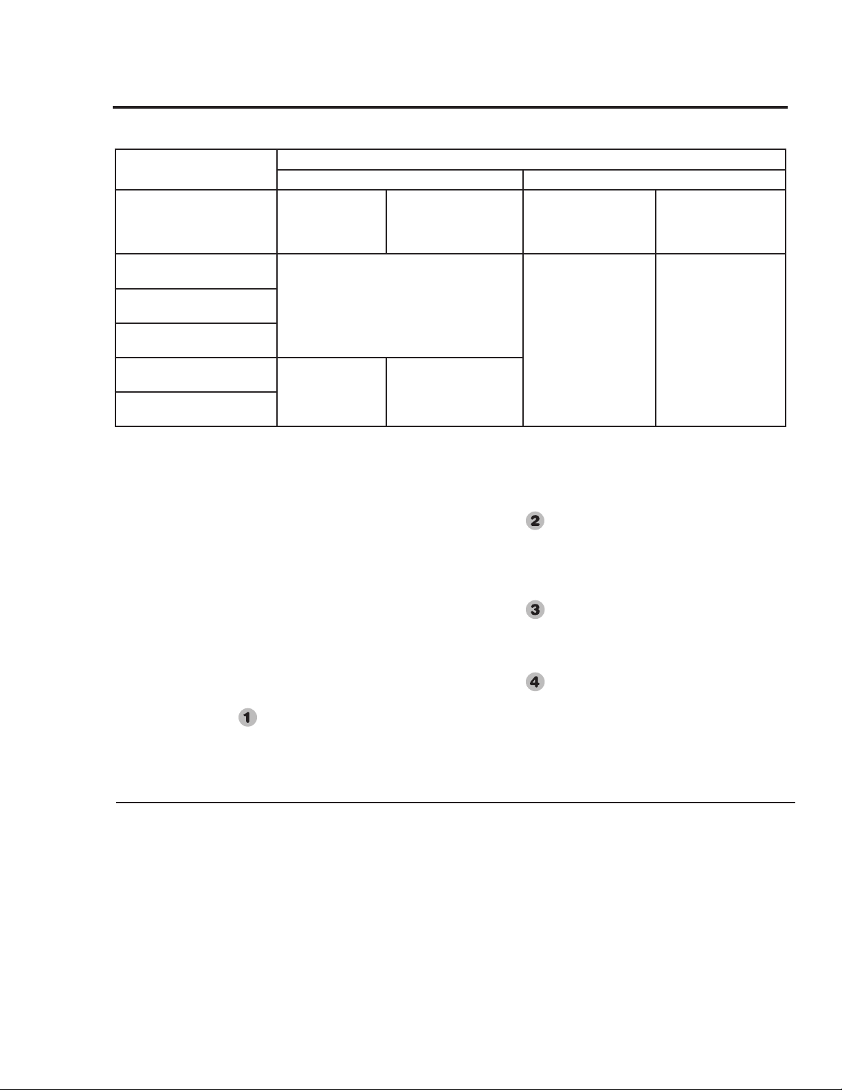
Ambient Installation Temperatures and Vent System Material Specications
Up to 100°F (38°C) 100°F (38°C) to 125°F (52°C)
Models
0 to 10 ft.
(0 to 3 m)
Equivalent Vent
System Length
10 ft. to Max.
(3 m to Max.)
Equivalent Vent System
Length
0 to 10 ft.
(0 to 3 m)
Equivalent Vent System
Length
10 ft. to Max.
(3 m to Max.)
Equivalent Vent System
Length
40 gallon, 40,000 & 38,000
Btu/hr. Models
PVC, CPVC, or ABS
CPVC or ABS PVC, CPVC, or ABS
50 Gallon, 40,000 Btu/hr.
Models
65 Gallon, 65,000 & 56,000
Btu/hr. Models
50 Gallon, 65,000 & 47,000
Btu/hr. Models
CPVC or ABS PVC, CPVC, or ABS
75 Gallon, 75,100 & 70,000
Btu/hr. Models
NOTICE: This water heater may be installed in attics provided ambient temperatures do not exceed 125°F (52°C) and
CPVC or ABS pipe and ttings are used for the entire vent system.
Loading ...
Loading ...
Loading ...