Loading ...
Loading ...
Loading ...
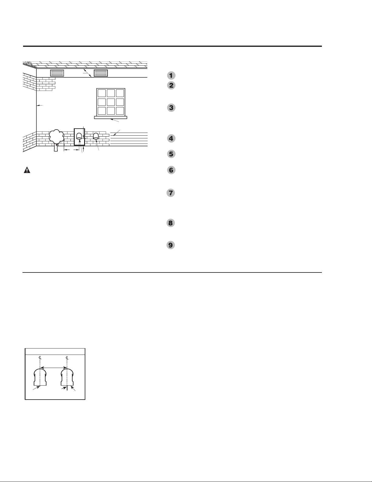
DO NOT install the vent terminal under any patio or deck.
To help prevent moisture from freezing on walls and under
eaves, do not locate the vent terminal on the side of a
building with prevailing winter winds.
When terminating the vent and combustion air-inlet pipes
through brick or masonry surfaces, the installation of a rust
resistant sheet metal backing plates behind the vent and
combustion air-inlet terminals are recommended.
DO NOT locate the vent terminal too close to shrubbery, as
flue gasses may damage them.
Caulk all cracks, seams and joints within 6 ft. (1.83 m) of
the vent and combustion air-inlet terminals.
Insulate vent pipe exposed to cold conditions (attics, crawl
spaces, etc.) with inflammable material to help prevent
moisture from accumulating in the vent pipe.
Support horizontal sections of the vent and combustion
air-inlet pipe every 4 ft. (1.22 m). DO NOT rigidly secure
the vent system. Provisions must be made to allow for
expansion and contraction of the vent system.
DO NOT install the vent and combustion air-inlet terminals
less than 1 ft. (30 cm) above grade or average snowfall
whichever is greater.
Permanently seal annular openings around the vent and
combustion air-inlet system penetrations using approved
materials to prevent entry of combustion products into the
building.
If soffit vent is too close,
block off and install new vent
at another location
Inside
corner
Caulk
Caulk
12 in. (30.5 cm)
min. above grade or
anticipated snow level
6 ft. (1.8 m) Caulk zone
or to edge of window etc.,
starting within 6 ft. (1.8 m)
Rising moisture will
collect under eves
4 ft.'
(1.22 m)
Vent
Combustion
Air-Inlet
WARNING: Moisture in the flue gas will condense as it
leaves the vent terminal. In cold weather this condensate can
freeze on the exterior wall, under the eaves and on
surrounding objects. Some discoloration to the exterior of
the building is to be expected. However, improper location or
installation can result in severe damage to the structure or
exterior finish of the building
19
Read these instructions thoroughly and make
sure you understand all steps and procedures
before proceeding with the installation.
Determine the locations for the vent and com-
bustion air-inlet terminals then make two (2)
holes through the exterior wall to accommodate
the vent and combustion air-inlet pipes.
• Maintain a minimum horizontal distance of
12 in. (30.5 cm) between the vent and com-
bustion air- inlet terminal centerlines.
Insert lengths of vent and combustion air-inlet
pipes through the wall as shown.
• Allow sufficient length of pipe to extend
beyond the exterior wall of the building for
attachment of the vent and combustion air-
inlet terminals.
Place the supplied 1/2 in. (1.3 cm) mesh metal
screens inside each terminal fitting.
NOTICE: For cold climates the screens may
be removed.
Connect the terminals to the vent and combus-
tion air-inlet pipes which are extending out of
the building.
• Ensure that the back of the supplied termi-
nals are flush with the outside wall surface.
Complete the installation of the remainder of
the vent system and attach it to the vent connec-
tor fitting on the water heater’s blower assem-
bly.
• Horizontal lengths of the vent system
must slope downward a minimum of
1/8 in. per foot (10 mm per m);
IMPORTANT: When the vent system cannot
be sloped away from the water heater or, if the
vent system has vertical section(s), then all hori-
Horizontal Vent and Combustion Air-Inlet Terminal
Installation
Vent Terminal Location Considerations
12 in.
(30.5cm) Min.
Wind Vane
Exhaust Vent
Terminal
Combustion Air-
Inlet Terminal
Loading ...
Loading ...
Loading ...