AP14896-3 (06/11)
!
FOR YOUR SAFETY!
— Do not store or use gasoline or other
flammable vapors or liquids or other
combustible materials in the vicinity of this or
any other appliance. To do so may result in an
explosion or fire.
— WHAT TO DO IF YOU SMELL GAS
l Do not try to light any appliance.
l Do not touch any electrical switch; do not
use any phone in your building.
l Immediately call your gas supplier from a
neighbor’s phone. Follow the gas supplier’s
instructions.
l If you cannot reach your gas supplier, call
the fire department.
l Do not return to your home until authorized
by the gas supplier or fire department.
— Improper installation, adjustment, alteration,
service or maintenance can cause property
damage, personal injury, or death. Refer to
this manual. Installation and service must be
performed by a qualified installer, service
agency or the gas supplier.
WARNING: If the information in these instructions is not followed exactly,
a fire or explosion may result causing property damage, personal injury or death.
!
The purpose of this manual is twofold: one, to provide the installer with the basic
directions and recommendations for the proper installation and adjustment of the
water heater; and two, for the owner–operator, to explain the features, operation,
safety precautions, maintenance and troubleshooting of the water heater. This
manual also includes a parts list.
It is very important that all persons who are expected to install, operate or adjust this
water heater read the instructions carefully so they may understand how to perform
these operations. If you do not understand these instructions or any terms within it,
seek professional assistance.
Any questions regarding the operation, maintenance, service or warranty of this
water heater should be directed to the seller from whom it was purchased. If
additional information is required, refer to the section on “If you need service.”
Do not destroy this manual. Please read carefully and keep in a safe place for
future reference.
!
Recognize this symbol as an indication of Important Safety Information!
!
California Proposition 65 Warning: This product contains chemicals known
to the State of California to cause cancer, birth defects or other reproductive
harm.
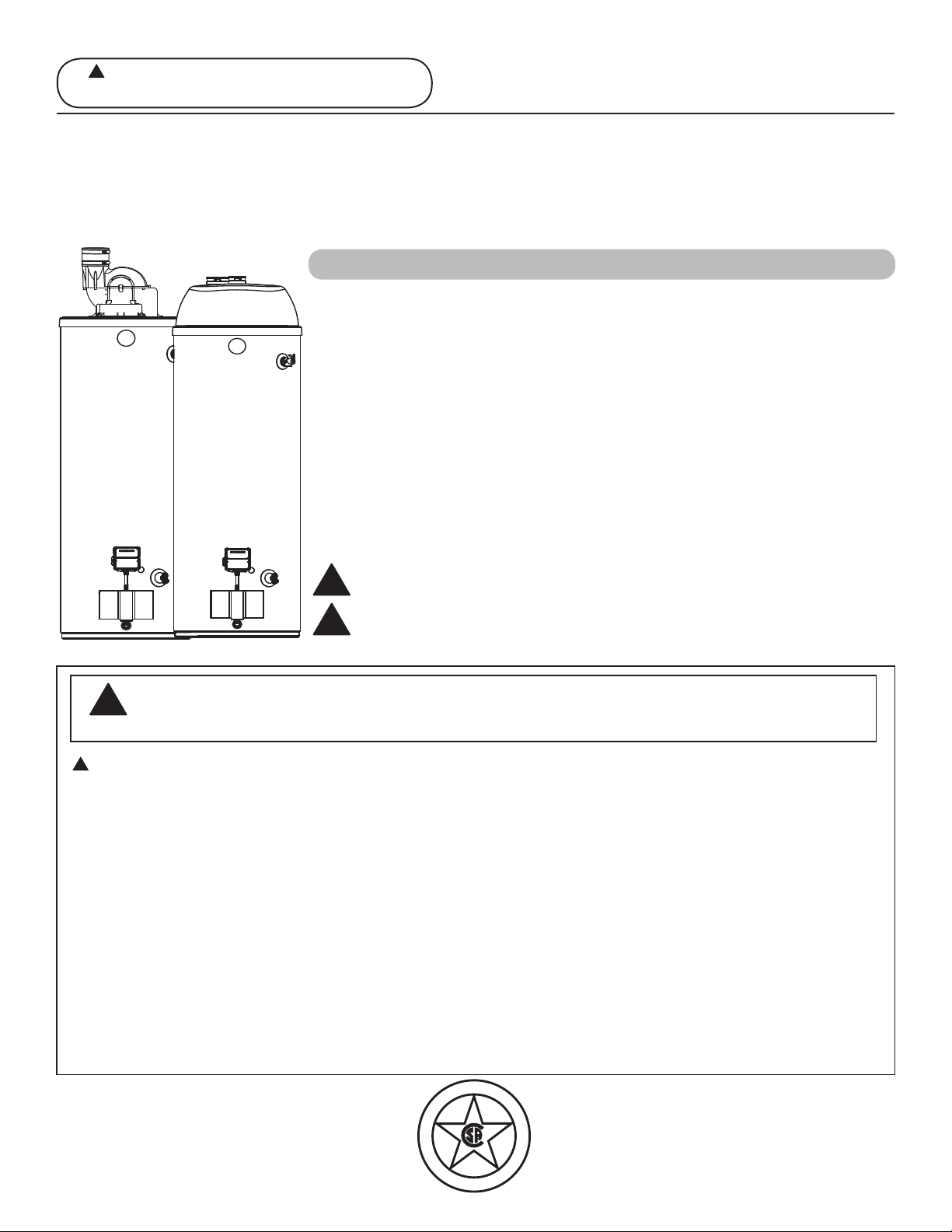
Residential 40, 50, 65 & 75 Gallon Models
Use & Care Manual
With Installation Instructions for the Installer
Printed in USA
Water Heaters
D
E
S
I
G
N
C
E
R
T
I
F
I
E
D
®
Residential Gas - FVIR Certified
PowerDirectVent
!
Warning: This water heater is not suitable
for use in manufactured (mobile) homes!
Care and Cleaning
Draining . . . . . . . . . . . . . . . . 38
Maintenance . . . . . . . . . . . . . 38
Vent System Inspection . . . . 39
Burner Inspection . . . . . . . . 39
Extended Shut-Down . . . . . .39
Safety Information
Safety Precautions . . . . . . . 3–6
LP Gas Models . . . . . . . . . . . 5
Installing the Water Heater
Location . . . . . . . . . . . . . . . . . 7
Water Supply Connections . . 8
Gas Supply . . . . . . . . . . . . . . 10
Vent and Combustion
Air-Inlet . . . . . . . . . . . . . . 11-27
Condensate Management . . .28
Wiring Diagram . . . . . . . . . . .29
Pipe Insulation . . . . . . . . . . . .30
Heat Traps . . . . . . . . . . . . . . .31
Installation Checklist . . . . . . .32
Potable/Space Heating . . . . 33
Operating Instructions
Lighting Instructions . . . . . . 34
Water Temperature . . . . .35-37
Troubleshooting Tips
Before You Call
For Service . . . . . . . . . . . 40-41
LED Codes . . . . . . . . . . . . . . .42
Customer Service
Parts List . . . . . . . . . . . . . . . . 43
If You Need Service . . . . . . .44
FOR YOUR RECORDS
Write the model and serial numbers here:
#
#
You can find them on a label on the appliance.
Staple sales slip or cancelled check here.
Proof of the original purchase date is needed to obtain service under
the warranty.
2
Inside you will find many helpful hints on how to use and maintain
your water heater properly. A little preventive care on your part can
save you time and money over the life of your water heater.
You’ll find many answers to common problems in the
Troubleshooting Guide. If you review the chart of Troubleshooting
Tips first, you may not need to call for service.
READ THIS MANUAL
Your safety and the safety of others are very important. There
are many important safety messages in this manual and on your
appliance. Always read and obey all safety messages.
!
This is the safety alert symbol. Recognize this symbol
as an indication of Important Safety Information!
This symbol alerts you to potential hazards that can
kill or hurt you and others.
All safety messages will follow the safety alert symbol and
either the word “DANGER”, “WARNING”, “CAUTION” or
“NOTICE”.
These words mean:
!
DANGER
An imminently hazardous situation
that will result in death or serious
injury.
!
WARNING
A potentially hazardous situation that
could result in death or serious injury
and/or damage to property.
!
CAUTION
A potentially hazardous situation that
may result in minor moderate injury.
NOTICE:
Attention is called to observe a
specified procedure or maintain a
specific condition.
READ THE SAFETY INFORMATION
Be sure to read and understand the entire Use and Care Manual before attempting to install or operate
this water heater. It may save you time and money. Pay particular attention to the Safety Instructions.
Failure to follow these warnings could result in serious bodily injury or death. Should you have problems
understanding the instructions in this manual, or have any questions, STOP, and get help from a
qualified service technician, or the local gas utility.
IMPORTANT SAFETY INFORMATION
READ ALL INSTRUCTIONS BEFORE USING
3
Failure to properly vent the water heater as outlined in the Vent and Combustion Air-Inlet
Section of the Installation Instructions in this manual can result in unsafe operation of the
water heater. To avoid the risk of fire, explosion, or asphyxiation from carbon monoxide,
never operate this water heater unless both the vent and combustion air-inlet systems are
properly installed. Be sure to inspect both the vent and combustion air-inlet for proper
installation at initial start-up; and at least periodically thereafter. Refer to the Care and
Cleaning section of this manual for more information regarding vent and combustion air-
inlet system inspection.
DANGER!
PROPERLY VENT THE WATER HEATER
Gasoline, as well as other flammable materials and liquids (which include but are not
limited to adhesives, solvents, paint thinners etc.), and the vapors they produce are
extremely dangerous. DO NOT handle, use or store gasoline or other flammable or
combustible materials anywhere near or in the vicinity of a water heater or any other
appliance. Be sure to read and follow warning label pictured below and other labels on the
water heater, as well as the warnings printed in this manual. Failure to do so can result in
property damage, bodily injury or death.
WARNING!
!
!
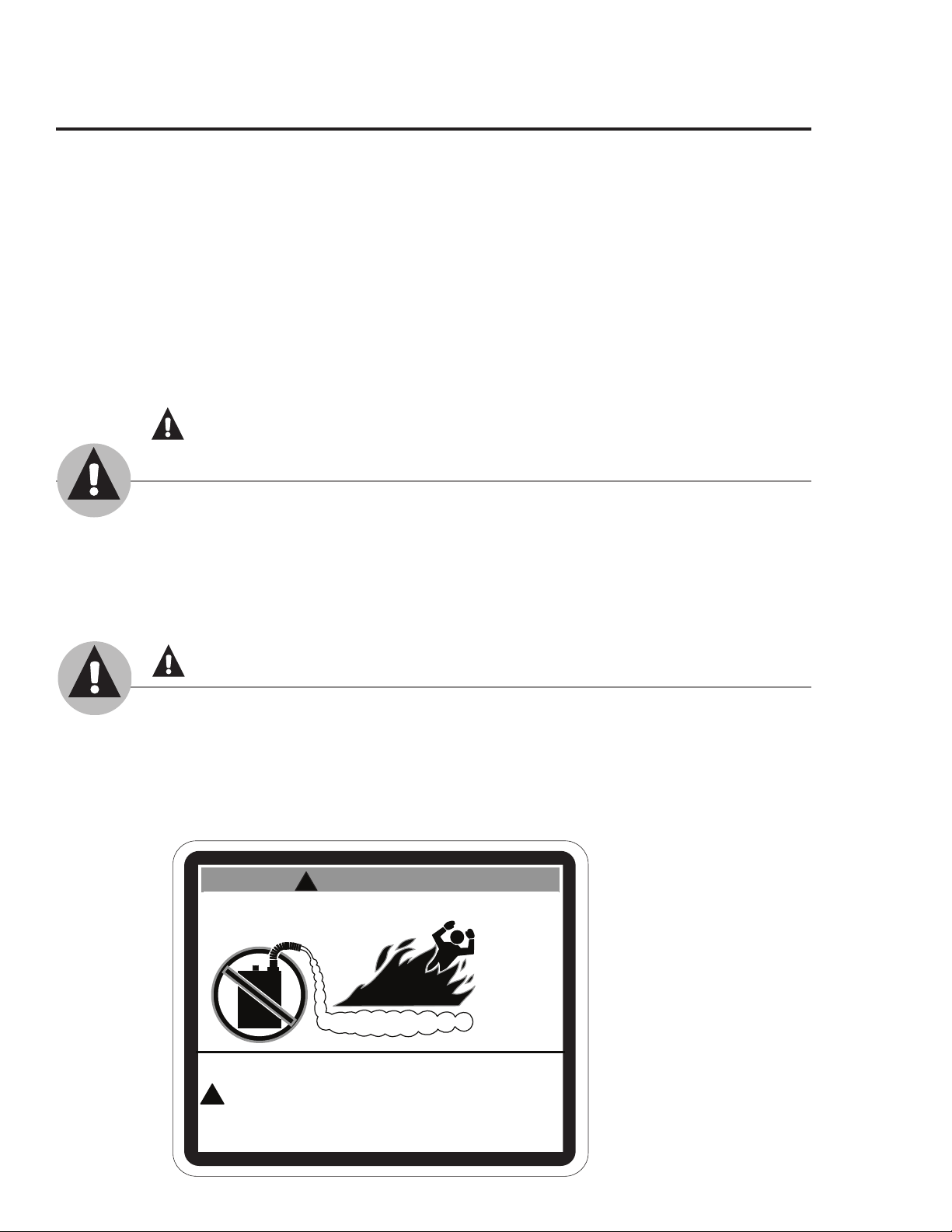
FLAMMABLES
Flammable Vapors
FIRE AND EXPLOSION HAZARD
Can result in serious injury or death.
Do not store or use gasoline or other flammable vapors and liquids
in the vicinity of this or any other appliance. Storage of or use of gasoline
or other flammable vapors or liquids in the vicinity of this or any other
appliance can result in serious injury or death.
W A R N I N G
NOTICE: This water heater is equipped with a flammable vapor sensor that will automatically shut
down the water heater in the presence of gasoline vapors and some other flammable vapors. If the
flammable vapor sensor shuts down the water heater, contact a qualified service technician. Clear any
hazardous materials and ventilate the area around the water heater. Do not turn off the appliance
or adjust the ON/OFF switch in any way. Do not tamper with the flammable vapor sensor. Do not
submerse the flammable vapor sensor in water. Do not allow the flammable vapor sensor to come into
contact with any substances such as bleach or cleaners. See the “Gas Valve LED Code” Section of this
manual for a list of diagnostic codes.
Time/Temperature Relationship in Scalds
Water Temperature Time To Produce a Serious Burn
120°F (49°C) More than 5 minutes
125°F (52°C) 1
1
/2 to 2 minutes
130°F (54°C) About 30 seconds
135°F (57°C) About 10 seconds
140°F (60°C) Less than 5 seconds
145°F (63°C) Less than 3 seconds
150°F (66°C) About 1
1
/2 seconds
155°F (68°C) About 1 second
Table courtesy of Shriners Burn Institute
The chart shown above may be used as a guide in
determining the proper water temperature for your home.
DANGER: Households with small children,
disabled, or elderly persons may require a 120°F
(49°C) or lower combination gas control (thermostat)
setting to prevent contact with "HOT" water.
Maximum water temperatures occur just after the burner
has shut off. To find water temperature being delivered,
turn on a hot water faucet and place a thermometer in the
water stream and read the thermometer. (See pages 35
and 36 for more details.)
The temperature of the water in the heater can be
regulated by pressing the "COOLER" or "HOTTER"
arrow buttons on the front of the combination
gas control. To comply with safety regulations the
combination gas control was set at its lowest setting
before the water heater was shipped from the factory.
The desired water temperature must be set.
The illustration below details the approximate water
temperature for each LED indicator of the combination
gas control's display.
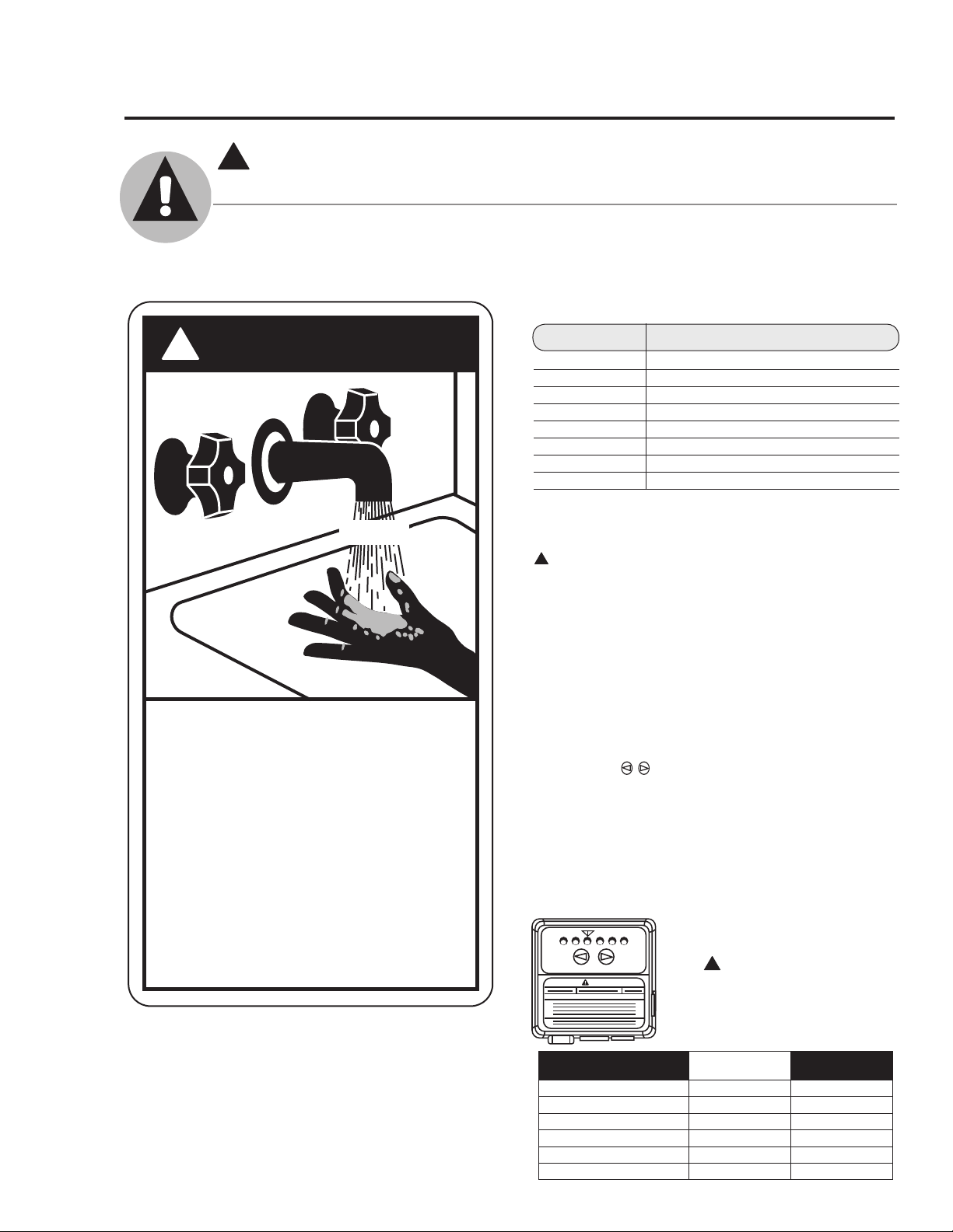
D A N G E R
!
HOT
Water temperature over 125°
can
cause severe burns
instantly or
death from scalds.
Children, disabled and elderly are
at highest risk of being scalded.
See instruction manual before
setting temperature at water
heater.
Feel water before bathing or
showering.
Temperature limiting valves are
available, see manual.
BURN
F
!
DANGER!
WATER TEMPERATURE SETTING
Safety and energy conservation are factors to be considered when selecting the water
temperature setting of a water heater’s combination gas control. Water temperatures above
125°F (52°C) can cause severe burns or death from scalding. Be sure to read and follow the
warnings outlined on the label pictured below. This label is also located on the water heater.
Notice: Mixing valves are available for reducing point of
use water temperature by mixing hot and cold water in
branch water lines. Contact a licensed plumber or the local
plumbing authority for further information.
4
IMPORTANT SAFETY INFORMATION.
READ ALL INSTRUCTIONS BEFORE USING
!
VACATION
WARNING
VERY
HOT
WARM
A B C
COOLER
HOTTER
Temperature Setting
Display
▼ A B C
Burns on Adult Skin
WARM = approx. 70°F (21°C)
● ○ ○ ○ ○ ○
--------------------
▼ = approx. 120°F (49°C)
○ ○ ● ○ ○ ○
More than 5 minutes
A = approx. 130°F (54°C)
○ ○ ○ ● ○ ○
About 30 seconds
B = approx. 140°F (60°C)
○ ○ ○ ○ ● ○
Less than 5 seconds
C = approx. 150°F (66°C)
○ ○ ○ ○ ○ ●
About 1-1/2 seconds
C-Flashing = approx. 160°F (71°C)
○ ○ ○ ○ ○ ●
About 1/2 seconds
!
DANGER: Hotter water
increases the potential for
Hot Water SCALDS.
5
LP and Natural gas have an odorant added to aid in detecting a gas leak. Some people
may not physically be able to smell or recognize this odorant. If you are unsure or
unfamiliar with the smell of LP or natural gas, ask the gas supplier. Other conditions,
such as “odorant fade”, which causes the odorant to diminish in intensity, can also hide or
camouflage a gas leak.
DANGER!
LIQUEFIED PETROLEUM (LP PROPANE OR BUTANE)
AND NATURAL GAS MODELS
l Water heaters utilizing LP gas are
different from natural gas models. A
natural gas water heater will not function
safely on LP gas and vice versa.
l No attempt should ever be made to
convert the water heater from natural
gas to LP gas. To avoid possible
equipment damage, personal injury or
fire, do not connect the water heater to a
fuel type not in accordance with the unit
data plate. LP for LP units. Natural gas
for natural gas units. These units are not
certified for any other fuel type.
l LP appliances should not be installed
below grade (for example, in a basement)
if such installation is prohibited by
federal, state and/or local laws, rules,
regulations or customs.
l LP gas must be used with great caution.
It is heavier than air and will collect first
in lower areas making it hard to detect at
nose level.
l Before attempting to light the water
heater, make sure to look and smell for
gas leaks. Use a soapy solution to check
all gas fittings and connections. Bubbling
at a connection indicates a leak that must
be corrected. When smelling to detect a
gas leak, be sure to sniff near the floor
also.
l Gas detectors are recommended in LP
& natural gas applications and their
installation should be in accordance
with the detector manufacturer’s
recommendations and/or local laws,
rules, regulations or customs.
l It is recommended that more than one
method, such as soapy solution, gas
detectors, etc., be used to detect leaks in
gas applications.
!
DANGER: If a gas leak is present or
suspected:
l Do not attempt to find the cause yourself.
l Do not try to light any appliance.
l Do not touch any electrical switch.
l Do not use any phone in your building.
l Leave the house immediately and make
sure your family and pets leave also.
l Leave the doors open for ventilation
and contact the gas supplier, a qualified
service agency or the fire department.
l Stay away from the house (or building)
until the service call has been made, the
leak is corrected and a qualified agency
has determined the area to be safe.
6
IMPORTANT SAFETY INFORMATION.
READ ALL INSTRUCTIONS BEFORE USING
!
WARNING!
For your safety, the information in this manual must be followed to minimize the risk of
fire or explosion, electric shock, or to prevent property damage, personal injury, or loss of
life.
FOR INSTALLATIONS IN THE STATE OF CALIFORNIA
California Law requires that residential water heaters must be braced, anchored or
strapped to resist falling or horizontal displacement due to earthquake motions. For
residential water heaters up to 52-gallon capacity, a brochure with generic earthquake
bracing instructions can be obtained from: Office of the State Architect, 1102 Q Street,
Suite 5100, Sacramento, CA 95814 or you may call 916-445-8100 or ask a water heater
dealer.
However, applicable local codes shall govern installation. For residential water heaters
of a capacity greater than 52 gallons, consult the local building jurisdiction for acceptable
bracing procedures.
Have the installer show you the location of the gas shut-off valve and how to shut it off
if necessary. Turn off the manual shut-off valve if the water heater has been subjected to
overheating, fire, flood, physical damage or if the gas supply fails to shut off.
l Read this manual entirely before installing
or operating the water heater.
l Use this appliance only for its intended
purpose as described in this Use and Care
Manual.
l Be sure your appliance is properly installed
in accordance with local codes and the
provided installation instructions.
l DO NOT attempt to repair or replace
any part of your water heater unless it is
specifically recommended in this manual.
All other servicing should be referred to a
qualified technician.
SAFETY PRECAUTIONS
READ AND FOLLOW THIS SAFETY INFORMATION
CAREFULLY.
SAVE THESE INSTRUCTIONS
IMPORTANT
Carefully inspect the water heater for damage before proceeding with the installation. Of specific
interest should be any dents in the long blue cover panel for the combustion air-inlet, PVC pipe; or
damages to the blower and the combustion air-inlet, PVC pipe assembly. If you find damage, DO
NOT install or attempt any repair to the water heater. Contact the manufacturer as detailed under "IF
YOU NEED SERVICE" on page 44.
7
Location
Installing the Water Heater
This water heater must be installed in accordance with these instructions, local codes, utility
company requirements, and/or in the absence of local codes, use the latest edition of the American
National Standard/National Fuel Gas Code. A copy can be purchased from either the American Gas
Association, 400 N. Capitol Street NW, Washington, DC 20001 as ANSI standard Z223.1 or National
Fire Protection Association, 1 Batterymarch Park, Quincy, MA 02269 as booklet NFPA 54.
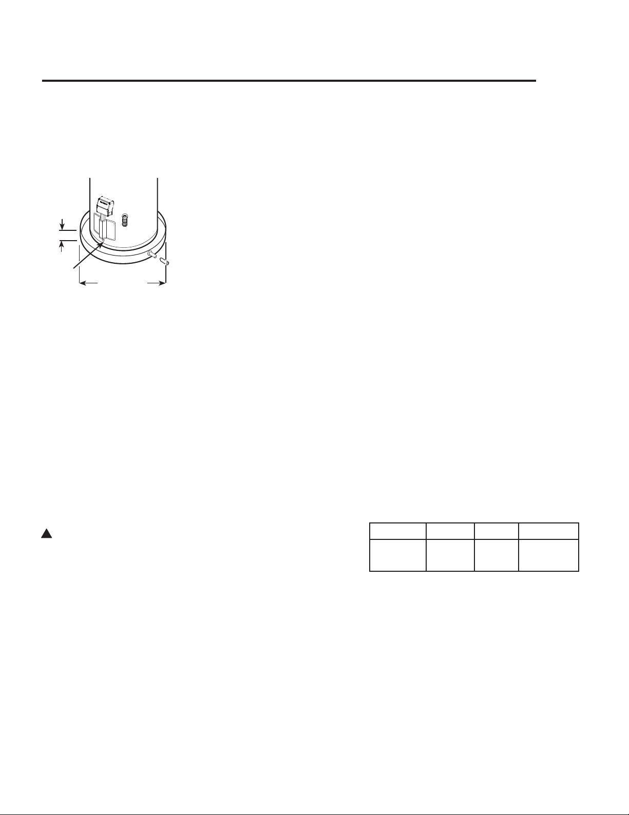
The auxiliary catch pan
installation MUST conform
with local codes.
Diameter of water
heater plus 2 in.
(5.1 cm) min.
Max.
2.75 in.
(7 cm)
!
WARNING: Combustible
construction refers to
adjacent walls and ceilings
and should not be confused
with combustible or
flammable products and
materials. Combustible
and/or flammable products
and materials should never
be stored in the vicinity of
this or any gas appliance.
Notice: DO NOT allow the
flammable vapor sensor to
become submerged in water.
Make sure the catch pan is
properly drained.
Flammable
Vapor
Sensor
Notice: DO NOT allow the
catch pan to obstuct the
flammable vapor sensor.
The water heater should not be located
in an area where leakage from the tank
or connections will result in damage
to the area adjacent to the heater or to
lower floors of the structure.
When such areas cannot be avoided it is
recommended that a suitable catch pan,
adequately drained, must be installed
under the water heater.
The water heater must be centered in the
catch pan.
Catch pan kits are available from the store
where the water heater was purchased, or
any water heater distributor.
Make certain the floor underneath the
water heater is strong enough to sufficient-
ly support the weight of the water heater
once it is filled with water.
This gas-fired water heater or any other
appliance should not be installed in a
space where liquids which give off flam-
mable vapors are to be used or stored.
Such liquids include gasoline, LP gas
(butane or propane), paint or adhesives,
thinners, solvents and/or combustible
removers.
DO NOT obstruct or block the Flammable
Vapor Sensor.
Because of natural air movement in a
room or other enclosed space, flammable
vapors can be carried some distance from
where liquids which give off flammable
vapors are to be used or stored. The open
flame of the water heater’s main burner
can ignite these vapors creating a shut
down condition which will not allow the
water heater to ignite.
Rheem Water Heating FVIR certified gas
water heaters can be installed on a residen-
tial garage floor without the use of an 18
in. (46 cm.) stand in accordance with the
National Fuel Gas Code, ANSI Z223.1/
NFPA 54, unless otherwise directed by
State and Local code requirements. The
water heater must be located so it is not
subject to physical damage, for example,
by moving vehicles, area flooding, etc.
● We recommend this water heater be
installed in locations where the ambient
temperatures do not exceed 100°F
(38°C).
IMPORTANT: Do not install the water
heater in a location where it may be
subjected to ambient temperatures
exceeding 125°F (52°C).
● The water heater should be installed so
as to minimize the length of plastic vent
and combustion air-inlet pipe and the
number of vent and combustion air-inlet
connection fittings required.
● See Vent and Combustion Air-Inlet
Section for vent system requirements.
● Hot water lines should be insulated to
conserve water and energy.
● Protect the water heater and water lines
from exposure to freezing temperatures.
● DO NOT install this water heater out-
doors.
● Minimum clearances from combustible
construction:
FrontV
Sides Rear
TopVV
5 in.
(12.7 cm)
0 in.
(0 cm)
0 in.
(0 cm)
12 in.
(30.5 cm)
V "Front" Clearance dimension is mea-
sured from the water heater jacket to
the closet door.
VV "Top" clearance dimension is mea-
sured from the jacket top of the water
heater to the ceiling.
● If the water heater is to be installed
directly on carpeting, the water heater
shall be installed on a metal or wood
panel extending beyond the full width
and depth of the water heater by at least
3 in. (7.6 cm) in all directions or, if
the water heater is to be installed in an
alcove or closet, the entire floor must be
covered by a wood or metal panel.

Thermal Expansion
Determine if a check valve exists in the inlet
water line. Check with your local water utility
company. It may have been installed in the cold
water line as a separate back flow preventer,
or it may be part of a pressure reducing valve,
water meter or water softener. A check valve
located in the cold water inlet line can cause
what is referred to as a “closed water system”.
A cold water inlet line with no check valve or
back flow prevention device is referred to as an
“open” water system.
As water is heated, it expands in volume and
creates an increase in the pressure within the
water system. This action is referred to as “ther-
mal expansion”. In an “open” water system,
expanding water which exceeds the capacity of
the water heater flows back into the city main
where the pressure is easily dissipated.
A “closed water system”, however, prevents
the expanding water from flowing back into the
main supply line, and the result of “thermal
expansion” can create a rapid and dangerous
pressure increase in the water heater and system
piping. This rapid pressure increase can quickly
reach the safety setting of the relief valve, caus-
ing it to operate during each heating cycle.
Thermal expansion, and the resulting rapid, and
repeated expansion and contraction of compo-
nents in the water heater and piping system can
cause premature failure of the relief valve, and
possibly the heater itself. Replacing the relief
valve will not correct the problem!
The suggested method of controlling thermal
expansion is to install an expansion tank in the
cold water line between the water heater and
the check valve (see illustration on page 9). The
expansion tank is designed with an air cushion
built in that compresses as the system pressure
increases, thereby relieving the over pressure
condition and eliminating the repeated operation
of the relief valve. Other methods of controlling
thermal expansion are also available. Contact
your installing contractor, water supplier or
plumbing inspector for additional information
regarding this subject.
8
Installing the Water Heater
Corrosive Atmospheres
The air in beauty shops, dry cleaning establish-
ments, photo processing labs, and storage areas
for liquid and powdered bleaches or swim-
ming pool chemicals often contain halogenated
hydrocarbons.
An air supply containing halogenated hydro-
carbons may be safe to breathe, but when it
passes through a gas flame corrosive elements
are released that will shorten the life of any gas
burning appliance.
Propellants from common spray cans or gas
leaks from A/C and refrigeration equipment are
highly corrosive after passing through a flame.
The water heater warranty is voided when fail-
ure of the heater is due to operation in a corro-
sive atmosphere.
NOTICE: The
water heater must
not be installed
near an air supply
containing halogenated
hydrocarbons.
Refer to the following illustration for suggested
typical installation. The installation of unions
or flexible copper connectors are recommended
on the hot and cold water connections so that
the water heater may be easily disconnected for
servicing if necessary. The HOT and COLD
water connections are clearly marked on the
water heater. Install a shutoff valve in the cold
water line near the water heater. Refer to the
following illustration for suggested typical
installation.
IMPORTANT
For models equipped with a Top Cap, it is rec-
ommended that the hot and cold water piping
have a minimum vertical height of 10 inches
(25.4 cm) from the top of the water heater
before transitioning into any elbow. This verti-
cal height is needed in order to provide adequate
clearance for Top Cap installation and removal.
To gain access to the hot and cold water con-
nections on models equipped with a Top Cap,
remove the two (2) screws that secure the top
cap to the water heater then pull the Top Cap
upward and off the water heater. See illustra-
tion of Top Cap and screws on pages 31 & 43.
Water Supply Connections
IMPORTANT: Do
not apply heat to the
HOT or COLD water
connections. If sweat
connections are used,
sweat tubing to adapter
before fitting adapter
to the cold water
connections on heater.
Any heat applied to
the cold water supply
fittings will permanently
damage the dip tube and
heat traps.
9
NOTICE: The National
Fuel Gas Code (NFGC)
mandates a manual
gas shut-off valve: See
(NFGC) for complete
instructions. Local codes
or plumbing authority
requirements may vary
from the instructions or
diagrams provided and
take precedent over these
instructions.
A new combination temperature and pressure relief valve, complying with the Standard for Relief Valves
and Automatic Gas Shut-Off Devices for Hot Water Supply Systems, ANSI Z21.22 /CSA 4.4, is factory
installed and must remain in the opening provided and marked for the purpose on the water heater. No
valve of any type should be installed between the relief valve and the tank. Local codes shall govern the
installation of relief valves.
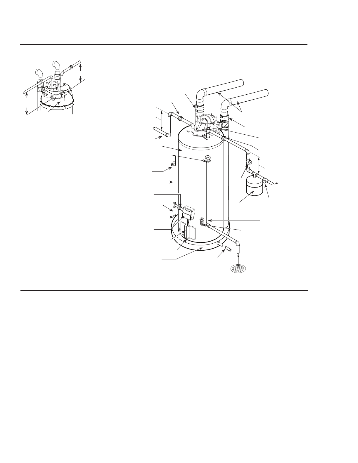
Typical Installation
Heat trap
6 in. (15.2 cm) min.
Heat trap
6 in. (15.2 cm) min.
Union (Optional)
To gas supply
Sediment trap
Cap
Union
Drain pan pipe
to suitable drain.
Drain
valve
Relief valve discharge
line to suitable open
drain.
To cold water
supply
6 in. (15.2 cm) min. air gap
Blower assembly
1/8 in. per foot (10 mm per meter)
maximum slope down away from
the water heater for horizontal
venting.
Optional catch pan
(if required).
Union (Optional)
Vent connector
Manual gas shut-off valve
Combination gas control
Jacket door
Temperature and pressure
relief valve
Shut-off valve
Shut-off
valve
Thermal expansion
tank (if required)
Hot water outlet to
fixtures
Water heater jacket
Flammable vapor sensor
Combustion air-inlet connector
Relief Valve
The pressure rating of the relief valve must
not exceed 150 psi (1,034 kPa), the maxi-
mum working pressure of the water heater
as marked on the rating plate.
The Btuh rating of the relief valve must
equal or exceed the Btuh input of the water
heater as marked on its rating plate.
Position the outlet of the relief valve above
a suitable open drain to eliminate potential
water damage. Piping used should be of a
type approved for hot water distribution.
The discharge line must be no smaller
than the outlet of the valve and must pitch
downward from the valve to allow complete
drainage (by gravity) of the relief valve and
discharge line.
The end of the discharge line should not be
threaded or concealed and should be pro-
tected from freezing. No valve of any type,
restriction, or reducer coupling must be
installed in the discharge line.
Alternate installation
detail for models
equipped with a Top Cap.
Top Cap
10"
(25.4 cm)
min.
10" (25.4 cm)
min.
WARNING: Do not
attempt to convert this
water heater for use with a
different type of gas other
than the type shown on the
rating plate. Such
conversion could result in
hazardous operating
conditions.
Gas Supply
The branch gas supply line to the water heater
should be clean properly sized steel pipe or
other approved gas piping material.
A union or ANSI design certified semi-rigid
or flexible gas appliance connector should be
installed in the gas line close to the water heater.
The National Fuel Gas Code (NFGC) mandates
a manual gas shutoff valve: See (NFGC) for
complete instructions.
If flexible connectors are used, the maximum
length shall not exceed 36 in. (91.4 cm) and
must meet the requirements in ANSI Z21.24/
CSA 6.10- Connectors for Gas Appliances.
Compound used on the threaded joints of the
gas piping must be of the type resistant to the
action of LP gas. Use compound sparingly on
male threads only.
Where a sediment trap is not incorporated as
part of the appliance, a sediment trap shall be
installed downstream of the equipment shutoff
valve as close to the inlet of the appliance as
practical at the time the appliance installation.
The sediment trap shall be either a tee fitting
with a capped nipple in the bottom outlet or
other device recognized as an effective sediment
trap.
Do not use excessive force over 31.5 ft. lbs.
(42.7 N●m) in tightening the pipe joint at the
combination gas control inlet, particularly if
teflon pipe compound is used, as the valve body
may be damaged.
The inlet gas pressure to the water heater must
not exceed 14.0 in. w.c. (3.5 kPa) w.c. for natu-
ral gas, or 14.0 in. w.c. (3.5 kPa) w.c. for LP
gas. For purposes of input adjustment, the mini-
mum inlet gas pressure (with main burner on) is
shown on the water heater rating plate. If high
or low gas pressures are present, contact your gas
supplier for correction.
10
To Fill the Water Heater
Make certain that the drain valve is closed, then
open the shut-off valve in the cold water supply
line.
Open each hot water faucet slowly to allow the
air to vent from the water
heater and piping.
A steady flow of water from all hot water
faucet(s) indicates a full water heater.
Do not allow the flammable vapor sensor to
become submerged in water.
WARNING: The tank
must be full of water
before the water heater is
turned on. The water
heater warranty does not
cover damage or failure
resulting from operation
with an empty or partially
empty tank.
Condensation
Condensation can also form on the tank when
it is first filled with water. Condensation
might also occur with a heavy water draw and
very cold inlet water temperatures. Drops of
water falling on the burner can produce a siz-
zling or pinging sound. This condition is not
unusual, and will disappear after the water
becomes heated. However, if condensation
continues, examine the piping and fittings for
possible leaks.
Installing the Water Heater
Leak Testing
The water heater and its gas connections must
be leak tested at normal operating pressures
before it is placed in operation.
Turn on the manual gas shut-off valve near
the water heater.
Use a soapy water solution to test for leaks
at all connections and fittings. Bubbles
indicate a gas leak that must be corrected.
The factory connections to the combination gas
control should also be leak tested after the water
heater is placed in operation.
WARNING: Never use
an open flame to test for
gas leaks, as property
damage, personal injury,
or death could result.

High Altitude
Pressure Testing the Gas Supply System
The water heater and its individual shut-off
valve must be disconnected from the gas
supply piping system during any pressure
testing of that system at test pressures in
excess 1/2 psi (3.5 kPa).
The water heater must be isolated from the
gas supply piping system by closing its
individual manual gas shutoff valve during
any pressure testing of the gas supply at
test pressures equal to or less than 1/2 psi
(3.5 kPa).
11
Vent and Combustion Air-Inlet
This water heater is a direct vent appli-
ance and must be installed so that all air
for combustion is derived directly from the
outside atmosphere and all flue gases are
discharged to the outside atmosphere. For
proper installation of the vent and combus-
tion air-inlet systems, follow the instruc-
tions as detailed in this manual. DO NOT
connect this water heater to an existing vent
or chimney - it must be vented separately
from all other appliances.
NOTICE: This water heater is approved
to use the following materials for pipe
of the vent and combustion air-inlet sys-
tems:
PVC (Schedule 40, Cellular Core,
ASTM-F891)
PVC (DWV, ASTM-D2665 or
CSA B181.2)
PVC (Schedule 40, ASTM-D1785 or
CSA B137.3)
PVC (SDR Series, ASTM-D2241 or
CSA B137.3)
CPVC (CPVC 4120, ASTM-D2846 or
CSA B137.6)
CPVC (Schedule 40, ASTM-F441 or
CSA B137.3)
CPVC (SDR Series, ASTM-F442)
ABS (Schedule 40, DWV, ASTM-D2661 or
CSA B181.1)
ABS (Schedule 40, DWV, Cellular Core,
ASTM-F628)
This water heater is approved to use the
following materials for the fittings of the
vent and combustion air-intake systems:
PVC (Schedule 40 DWV, ASTM D2665)
CPVC (Schedule 40, ASTM F438)
ABS (Schedule 40 DWV, ASTM D2661)
DO NOT mix ABS pipe and fittings with
PVC or CPVC pipe fittings. Note: It
is acceptable to interchange PVC and
CPVC pipe and fittings.
Vent and combustion air-inlet systems must
be adequately supported along both vertical
and horizontal lengths.
The vent and combustion air-inlet sys-
tems of this water heater may be installed
horizontally through a wall or vertically
through the roof.
Maximum unsupported length is recom-
mended to be no more than 4 feet (1.22 m).
It is imperative that the first hanger be
located on the horizontal length immedi-
ately adjacent to the first 90-degree elbow
from the vertical rise of vent pipe connect-
ed to the water heater.
DANGER: Failure to
properly install the vent
and combustion air-inlet
systems as outlined in the
Vent and Combustion Air-
Inlet section of this
manual will result in
unsafe operation of the
water heater causing
bodily injury, explosion,
fire or death.
To avoid the risk of fire,
explosion, or asphyxiation
from carbon monoxide,
NEVER operate the
water heater unless it is
properly vented and the
vent and combustion air-
inlet systems are properly
installed as detailed in the
"Vent and Combustion
Air-Inlet" section of this
manual.
The vent and combustion
air inlet pipes must
overlap a minimum of 1/2
in. (1.3 cm) at each joint.
It is important that the
vent and combustion air-
inlet pipes engage fully
into any pipe fitting and
be kept in that position
until the adhesive has
fully cured. DO NOT
drill or punch holes in the
plastic pipe or fittings.
Input rating of this water heater is based on
sea level operation. At higher elevations
the actual input rate may be lower than the
value listed on the rating label due to the
derating of Natural Gas and LP Gas. For
Power Direct Vent models listed in the
venting tables that do not show venting
configurations above 7,700 ft. (2,347 m),
contact the water heater manufacturer for a
required High Altitude Kit that will allow
the specific water heater model to operate
at altitudes between 7,700 ft. (2,347 m) and
10,200 ft. (3,109 m). See page 44.
!
WARNING: Failure
to install a water heater
suitable for the altitude at
the location it is intended
to serve, can result in
improper operation of
the appliance resulting
in property damage and/
or producing carbon
monoxide gas, which
could result in personal
injury, or death.
12
The support method used should isolate the vent
and combustion air-inlet pipes from floor joists
or other structural members to help prevent the
transmission of noise and vibration.
Do not support, pin or otherwise secure the vent
and combustion air-inlet systems in a way that
restricts the normal thermal expansion and con-
traction of the chosen venting material.
If the water heater is being installed as a
replacement for an existing power direct vent
water heater, a thorough inspection of the exist-
ing vent and combustion air-inlet systems must
be performed prior to any installation work.
Verify that the correct materials as speci-
fied in this manual have been used, and
that the minimum or maximum vent and
combustion air-inlet lengths and terminal
locations as detailed in this manual have
been met.
Carefully inspect the entire vent and com-
bustion air-inlet systems for any signs of
cracks or fractures, particularly at the joints
between elbows or other fittings and the
straight length of vent pipe.
Check the vent and combustion air-inlet for
signs of sagging or other stresses in the
joints as a result of misalignment of any
components in the systems.
If any of the conditions above are found,
they must be corrected in accordance with
the instructions in this manual before com-
pleting the installation and putting the
water heater into service.
Read these instructions thoroughly and make
sure you understand all steps and procedures
before proceeding with the installation.
1. Connect the vent system piping to the
blower assembly using the already installed
2 in. (5.1 cm) diameter rubber coupling and
clamps.
2. Connect the combustion air-inlet system
piping to the combustion air-inlet piping tee
using the 2 in. (5.1 cm) already installed
rubber coupling and clamps (See Figure 1).
3. For vent and combustion air-inlet terminals,
use the two (2), 2 in. (5.1 cm) diameter,
Schedule 40, PVC, 90°, 1/4 standard bend
elbows supplied with the water heater.
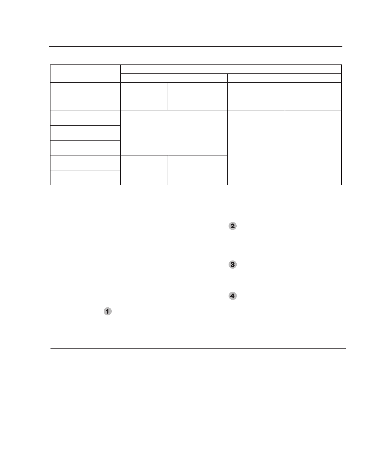
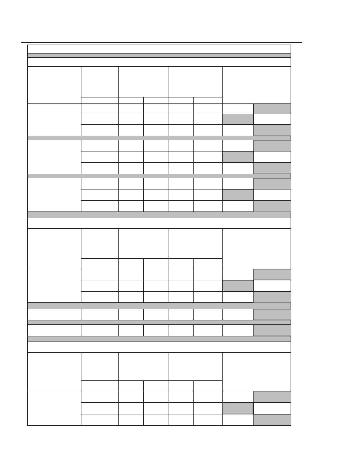
Maximum and Minimum Vent and Combustion Air-Inlet Lengths for Power
Direct Vent Models:
40 Gallon with Inputs of 40,000 & 38,000 Btu/h
50 Gallon with Input of 40,000 Btu/h
Additional installation information for The Common-
wealth of Massachusetts is located on the back page
of this manual.
NOTICE: This unit
is equipped with a
Flammable Vapor Sensor.
Do not supply electrical
power to the water heater
until enough time has
passed to allow the vapors
from the primer and
cement to dissipate.
Vent and Combustion Air-Inlet continued -
Installing the Water Heater
Ambient Installation Temperatures and Vent System Material Specications
Up to 100°F (38°C) 100°F (38°C) to 125°F (52°C)
Models
0 to 10 ft.
(0 to 3 m)
Equivalent Vent
System Length
10 ft. to Max.
(3 m to Max.)
Equivalent Vent System
Length
0 to 10 ft.
(0 to 3 m)
Equivalent Vent System
Length
10 ft. to Max.
(3 m to Max.)
Equivalent Vent System
Length
40 gallon, 40,000 & 38,000
Btu/hr. Models
PVC, CPVC, or ABS
CPVC or ABS PVC, CPVC, or ABS
50 Gallon, 40,000 Btu/hr.
Models
65 Gallon, 65,000 & 56,000
Btu/hr. Models
50 Gallon, 65,000 & 47,000
Btu/hr. Models
CPVC or ABS PVC, CPVC, or ABS
75 Gallon, 75,100 & 70,000
Btu/hr. Models
NOTICE: This water heater may be installed in attics provided ambient temperatures do not exceed 125°F (52°C) and
CPVC or ABS pipe and ttings are used for the entire vent system.
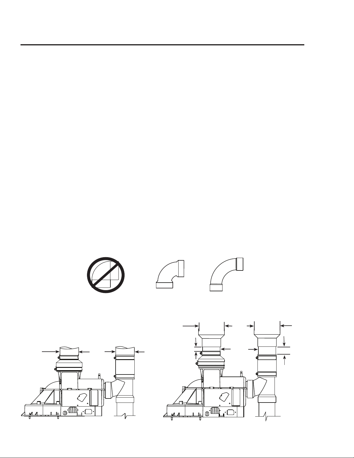
This water heater may also be installed with 3 in. (7.6 cm)
diameter pipe and fittings for the vent and combustion air-
inlet systems.
To connect the vent system piping:
• Install a straight length of 2 in. (5.1 cm) diameter pipe
to the rubber coupling on the blower assembly,
• Followed by a 2 in. (5.1 cm) to 3 in. (7.6 cm) diameter
pipe increaser fitting (See Figure 2).
To connect the combustion air-inlet system piping:
• Install a straight length of 2 in. (5.1 cm) diameter pipe
to the combustion air-inlet piping tee coupling,
• Followed by a 2 in. (5.1 cm) to 3 in. (7.6 cm) diameter
pipe increaser fitting (See Figure 2).
For vent and combustion air-inlet terminals,
• Use 3 in. (7.6 cm) diameter, Schedule 40, PVC, 90°,
1/4 standard bend elbows (not supplied).
DO NOT use unequal diameters of pipe and fittings
for the vent and combustion air-inlet systems except as
defined previously.
NOTICE: The difference between the vent and
combustion air-inlet system equivalent lengths must be
no greater than 5 ft. (1.5 m).
IMPORTANT: Ensure that all the coupling clamps are
tightened before allowing the water heater to operate.
When using CPVC or ABS pipe and fittings, use 90°
elbows of the corresponding size and material for the vent
terminal and combustion air-inlet terminals.
The vent and combustion air-inlet terminals of the
water heater must be installed in the same atmospheric
pressure zone.
The minimum and maximum equivalent lengths for the
vent and combustion air-inlet systems are shown in
Table 1.
• Maintain a minimum vertical height of 1 ft. (30.5 cm)
of pipe, including pipe increasers (if used), from the
blower exhaust coupling before transitioning into any
elbow.
• The vent and combustion air-inlet terminations are not
included in the equivalency calculations.
NOTICE: A 90°, 1/4 standard bend or long bend elbow
is equivalent to 5 ft. (1.52 m) of straight pipe.
A 45°, 1/8 standard bend or long bend elbow is
equivalent to 2.5 ft. (0.76 m) of straight pipe.
DO NOT use short bend elbows. Use only standard and/
or long bend elbows. See examples below.
13
Figure 1
Vent
Combustion air-inlet
2 in.
(5.1cm)
pipe
diameter
2 in.
(5.1cm)
pipe
diameter
Figure 2
3 in.
(7.6 cm) pipe
diameter
Vent
Combustion air-inlet
# Min. 2 1/2 in.
(6.4 cm) to
6 in. (15.2 cm)
Max.Spacing
# Min. 2 1/2 in.
(6.4 cm) to
6 in. (15.2 cm)
Max. Spacing
Long Bend 90° Elbow
Standard Bend 90° Elbow
Short Bend 90° Elbow
Do Not Use
Elbow Examples
OK to Use OK to Use
#
#
Installing the Water Heater
Table 1
From Sea Level through 5,999 ft. (1,828 m) Above Sea Level
Model
Vent &
Combustion
Air-Inlet System
Diameter
Min. Allowed Equivalent
Vent & Combustion Air-
Inlet Lengths (Each Pipe
Run)
Max. Allowed Equivalent
Vent & Combustion Air-
Inlet Lengths (Each Pipe
Run)
Vent and Combustion Air-Inlet System
Termination(s)
Inches Feet Meters Feet Meters
40 Gallon, 40,000
& 38,000 Btu/hr.
Models
2 7 2 30 9 90° Elbows Concentric*
3 7 2 60 18 90° Elbows
3 7 2 50 15 Concentric*
50 Gallon, 40,000
Btu/hr. Models
2 7 2 30 9 90° Elbows Concentric*
3 7 2 60 18 90° Elbows
3 7 2 50 15 Concentric*
From 6,000 ft. (1,828 m) Above Sea Level through 7,700 ft. (2,347 m) Above Sea Level
Model
Vent &
Combustion
Air-Inlet System
Diameter
Min. Allowed Equivalent
Vent & Combustion Air-
Inlet Lengths (Each Pipe
Run)
Max. Allowed Equivalent
Vent & Combustion Air-
Inlet Lengths (Each Pipe
Run)
Vent and Combustion Air-Inlet System
Termination(s)
Inches Feet Meters Feet Meters
40 Gallon, 40,000
& 38,000 Btu/hr.
Models
2 7 2 15 4.5 90° Elbows
2 7 2 30 9 Concentric*
3 7 2 60 18 90° Elbows
3 7 2 50 15 Concentric*
50 Gallon, 40,000
Btu/hr. Models
2 7 2 15 4.5 Concentric*
3 7 2 60 18 90° Elbows
3 7 2 50 15 Concentric*
From 7,701 ft. (2,347 m) Above Sea Level through 10,200 ft. (3,109 m) Above Sea Level
Model
Vent & Combus-
tion Air-Inlet
System Diameter
Min. Allowed Equivalent
Vent & Combustion Air-
Inlet Lengths (Each Pipe
Run)
Max. Allowed Equivalent
Vent & Combustion Air-
Inlet Lengths (Each Pipe
Run)
Vent and Combustion Air-Inlet System
Termination(s)
Inches Feet Meters Feet Meters
40 Gallon, 40,000
& 38,000 Btu/hr.
Models
2 7 2 15 4.5 Concentric*
3 7 2 60 18 90° Elbows
3 7 2 50 15 Concentric*
50 Gallon, 40,000
Btu/hr. Models
3 7 2 60 18 90° Elbows
3 7 2 50 15 Concentric*
14
*Use only Rheem 3 in. (7.6 cm) concentric termination.

Read these instructions thoroughly and make sure
you understand all steps and procedures before
proceeding with the installation.
1. Connect the vent system piping to the blower
assembly using the already installed 3 in.
(7.6 cm) diameter rubber coupling and
clamps.
2. Connect the combustion air-inlet system
piping to the combustion air-inlet piping tee
using the 3 in. (7.6 cm) already installed
rubber coupling and clamps (See Figure 3).
3. For vent and combustion air-inlet terminals,
use the two (2), 3 in. (7.6 cm) diameter,
Schedule 40, PVC, 90°, 1/4 standard bend
elbows supplied with the water heater.
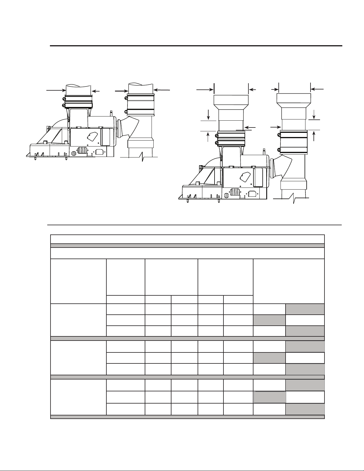
This water heater may also be installed with 4 in.
(10.2 cm) diameter pipe and fittings for the vent
and combustion air-inlet systems
To connect the vent system piping,
• Install a straight length of 3 in. (7.6 cm)
diameter pipe to the rubber coupling on the
blower assembly,
• Followed by a 3 in. (7.6 cm) to 4 in.
(10.2 cm) diameter pipe increaser fitting
(See Figure 4).
To connect the combustion air-inlet system piping,
• Install a straight length of 3 in. (7.6 cm)
diameter pipe to the combustion air-inlet
piping tee coupling,
• Followed by a 3 in. (7.6 cm) to 4 in.
(10.2 cm) diameter pipe increaser fitting
(See Figure 4).
For vent and combustion air-inlet terminals,
• Use 3 in. (7.6 cm) diameter, Schedule 40,
PVC, 90°, 1/4 standard bend elbows (not
supplied).
DO NOT use unequal diameters of pipe and
fittings for the vent and combustion air-inlet
systems except as defined previously.
NOTICE: The difference between the vent and
combustion air-inlet system equivalent lengths
must be no greater than 5 ft. (1.5 m).
IMPORTANT: Ensure that all the coupling
clamps are tight before allowing the water heater
to operate.
When using CPVC or ABS pipe and fittings, use
90° elbows of the corresponding size and material
for the vent terminal and combustion air-inlet
terminals.
The vent and combustion air-inlet terminals of
the water heater must be installed in the same
atmospheric pressure zone.
The minimum and maximum equivalent lengths
for the vent and combustion air-inlet systems are
shown in Table 2.
• Maintain a minimum vertical height of 1 ft.
(30.5 cm) of pipe, including pipe increasers
(if used), from the blower exhaust coupling
before transitioning into any elbow.
• The vent and combustion air-inlet
terminations are not included in the
equivalency calculations.
NOTICE: A 90°, 1/4 standard bend or long
bend elbow is equivalent to 5 ft. (1.52 m) of
straight pipe. A 45°, 1/8 standard bend or long
bend elbow is equivalent to 2.5 ft. (0.76 m) of
straight pipe.
DO NOT use short bend elbows. Use only
standard and/or long bend elbows. See examples
below.
15
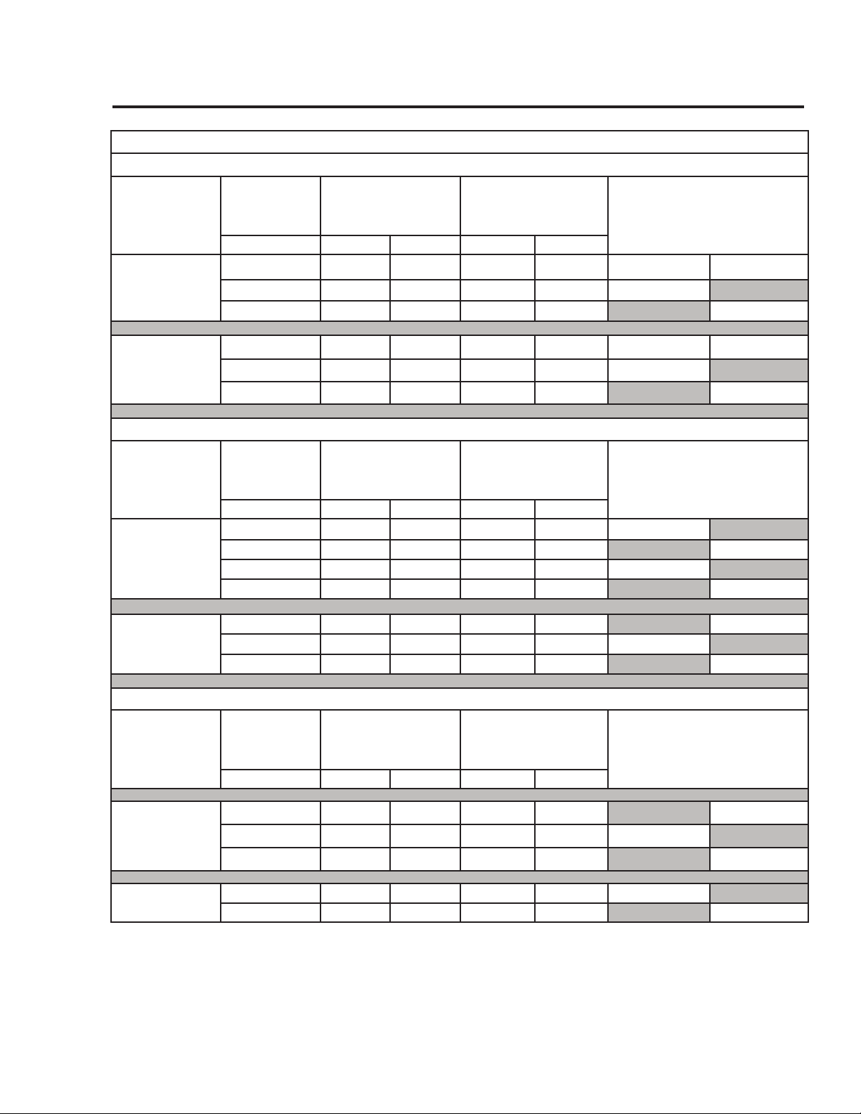
Maximum and Minimum Vent and Combustion Air-Inlet Lengths For
Power Direct Vent Models:
50 Gallon With Inputs of 65,000 & 47,000 Btu/h
65 Gallon With Inputs of 65,000 & 56,000 Btu/h
75 Gallon With Inputs of 75,100 & 70,000 Btu/h
Elbow Examples
Long Bend 90° Elbow
Standard Bend 90° Elbow
Short Bend 90° Elbow
Do Not Use OK to Use OK to Use
16
Installing the Water Heater
Table 2
From Sea Level through 2,000 ft. (609 m) Above Sea Level
Model
Vent &
Combustion
Air-Inlet System
Diameter
Min. Allowed
Equivalent Vent &
Combustion Air-Inlet
Lengths (Each Pipe
Run)
Max. Allowed Equivalent
Vent & Combustion Air-
Inlet Lengths (Each Pipe
Run)
Vent and Combustion Air-Inlet
System Termination(s)
Inches Feet Meters Feet Meters
50 Gallon, 65,000 &
47,000 Btu/hr. Models
3 7 2 50 15 90° Elbows
3 7 2 40 12 Concentric*
4 7 2 100 30 90° Elbows
65 Gallon, 65,000 &
56,000 Btu/hr. Models
3 8 2.5
50 15 90° Elbows
3 8 2.5 40 12 Concentric*
4 8 2.5
100 30 90° Elbows
75 Gallon, 75,100
&70,000 Btu/hr. Models
3 8 2.5
50 15 90° Elbows
3 8 2.5 40 12 Concentric*
4 8 2.5
100 30 90° Elbows
Figure 3
3 in.
(7.6 cm)
pipe diameter
Vent
Combustion air-inlet
3 in.
(7.6 cm)
pipe diameter
Figure 4
4 in.
(10.2 cm)
pipe diameter
Vent
Combustion air-inlet
# Min. 2 1/2 in.
(6.4 cm) to
6 in. (15.2
cm) Max.
Spacing
# Min. 2 1/2 in.
(6.4 cm) to
6 in. (15.2
cm) Max.
Spacing
*Use only Rheem 3 in. (7.6 cm) concentric termination.
#
#
17
*Use only Rheem 3 in. (7.6 cm) concentric termination.
Table 2 - Continued
From 2,000 ft. (609 m) Above Sea Level through 5,999 ft. (1,828 m) Above Sea Level
Model
Vent &
Combustion
Air-Inlet System
Diameter
Min. Allowed
Equivalent Vent &
Combustion Air-Inlet
Lengths (Each Pipe
Run)
Max. Allowed Equivalent
Vent & Combustion Air-
Inlet Lengths (Each Pipe
Run)
Vent and Combustion Air-Inlet
System Termination(s)
Inches Feet Meters Feet Meters
50 Gallon, 65,000 &
47,000 Btu/hr. Models
3 7 2 50 15 90° Elbows
3 7 2 40 12 Concentric*
4 7 2 100 30 90° Elbows
65 Gallon, 65,000 &
56,000 Btu/hr. Models
3 8 2.5 30 9 90° Elbows
3 8 2.5 20 6 Concentric*
4 8 2.5
100 30 90° Elbows
75 Gallon, 75,100 &
70,000 Btu/hr. Models
3 8 2.5
25 8 90° Elbows
3 8 2.5 20 6 Concentric*
4 8 2.5 100 30 90° Elbows
From 6,000 ft. (1,829 m) Above Sea Level through 7,700 ft. (2,347 m) Above Sea Level
Model
Vent &
Combustion
Air-Inlet System
Diameter
Min. Allowed
Equivalent Vent &
Combustion Air-Inlet
Lengths (Each Pipe
Run)
Max. Allowed Equivalent
Vent & Combustion Air-
Inlet Lengths (Each Pipe
Run)
Vent and Combustion Air-Inlet
System Termination(s)
Inches Feet Meters Feet Meters
50 Gallon, 65,000 &
47,000 Btu/hr. Models
3 7 2
50 15 90° Elbows
3 7 2 40 12 Concentric
4 7 2 100 30 90° Elbows
65 Gallon, 65,000 &
56,000 Btu/hr. Models
4 8 2.5 40 12 90° Elbows
75 Gallon, 75,100 &
70,000 Btu/hr. Models
4 8 2.5 50 15 90° Elbows
From 7,701 ft. (2,347 m) Above Sea Level through 10,200 ft. (3,109 m) Above Sea Level
Model
Vent &
Combustion
Air-Inlet System
Diameter
Min. Allowed
Equivalent Vent &
Combustion Air-Inlet
Lengths (Each Pipe
Run)
Max. Allowed Equivalent
Vent & Combustion Air-
Inlet Lengths (Each Pipe
Run)
Vent and Combustion Air-Inlet
System Termination(s)
Inches Feet Meters Feet Meters
50 Gallon, 65,000 &
47,000 Btu/hr. Models
3 7 2 25 8 90° Elbow
3 7 2 20 6 Concentric*
4 7 2 100 30 90° Elbow
18
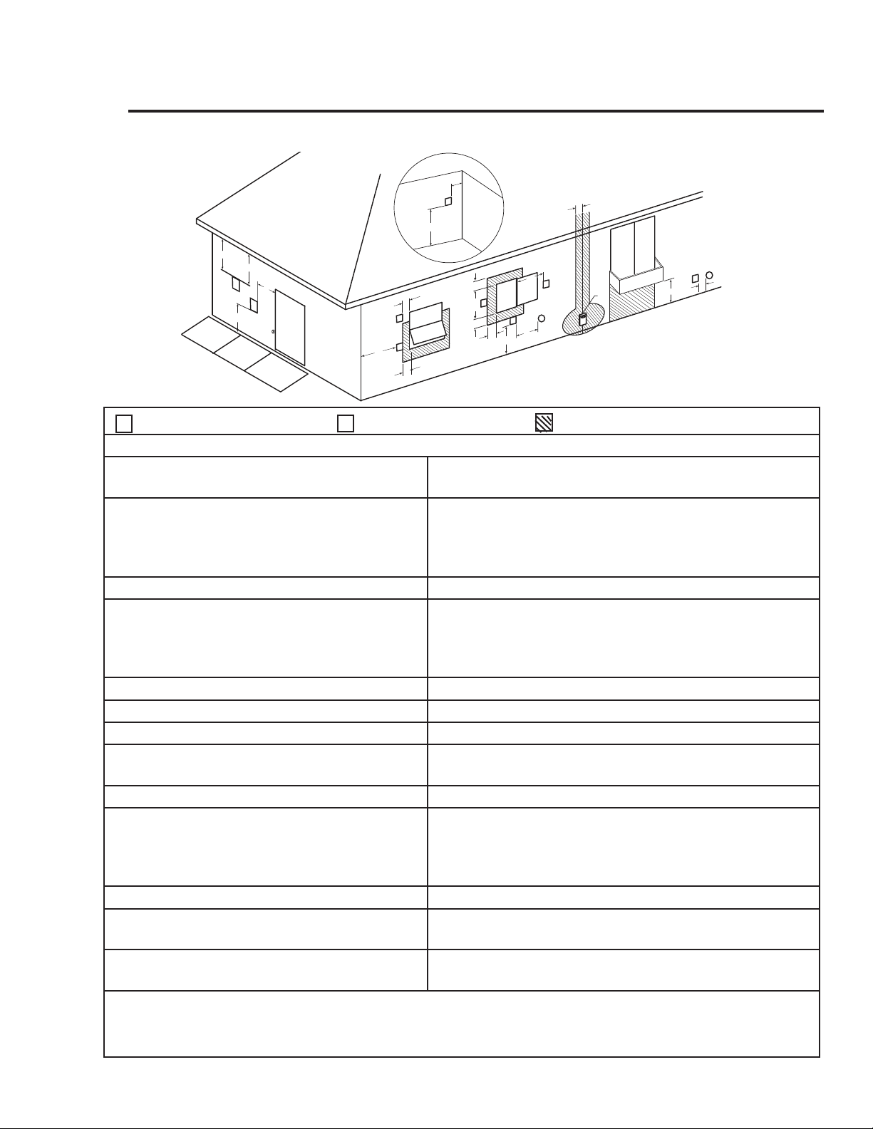
Direct Vent Terminal Clearances
D
V
V
E
FIXED
CLOSED
O
P
ERAB
LE
O
PERABLE
FIXED
CLOSED
v
v
B
L
F
C
B
v
v
v
X
B
B
B
A
J
B
I
H
X
v
M
K
v
G
A
V Vent Terminal X Air Supply Inlet Area Where Terminal Is Not Permitted
US Installations
1
A = Clearance above grade, veranda, porch,
deck or balcony
1 ft. (30 cm)
B = Clearance to window or door that may be
opened
6 in. (15 cm) for appliances ≤ 10,000 Btuh (3 kW),
9 in. (23 cm) for appliances > 10,000 Btuh (3kW) and ≤
50,000 Btuh (15 KW),
12 in. (30 cm) for appliances> 50,000 Btuh (15 kW)
C = Clearance to permanately closed window *
D = Vertical clearance to ventilated soft lo-
cated above the terminal within a horizontal
distance of 2 feet (61 cm) from the center
line of the terminal
*
E - Clearance to unventilated soft *
F - Clearance to outside corner *
G - Clearance to inside corner *
H - Clearance to each side of centerline extend-
ed above meter/regulator assembly
*
I - Clearance to service regulator vent outlet *
J - Clearance to nonmechanical air supply inlet
to building or the combustion air inlet to any
other appliance
6 in. (15 cm) for appliances ≤ 10,000 Btuh (3 kW),
9 in. (23 cm) for appliances > 10,000 Btuh (3kW) and ≤
50,000 Btuh (15 KW),
12 in. (30 cm) for appliances> 50,000 Btuh (15 kW)
K - Clearance to a mechanical air supply inlet 3 ft. (91 cm) above if within 10 ft. (3 m) horizontally
L - Clearance above paved sidewalk or paved
driveway located on public property
*
M - Clearance under veranda, porch, deck, or
balcony
*
1
In accordance with the current ANSI Z223.1/ NFPA 54 National Fuel Gas Code
* For clearances not specied in ANSI Z223.1/ NFPA 54 the following statement shall be included:
"Clearance in accordance with local installation codes and the requirements of the gas supplier and the manufacturer's installation
instructions".
Installing the Water Heater
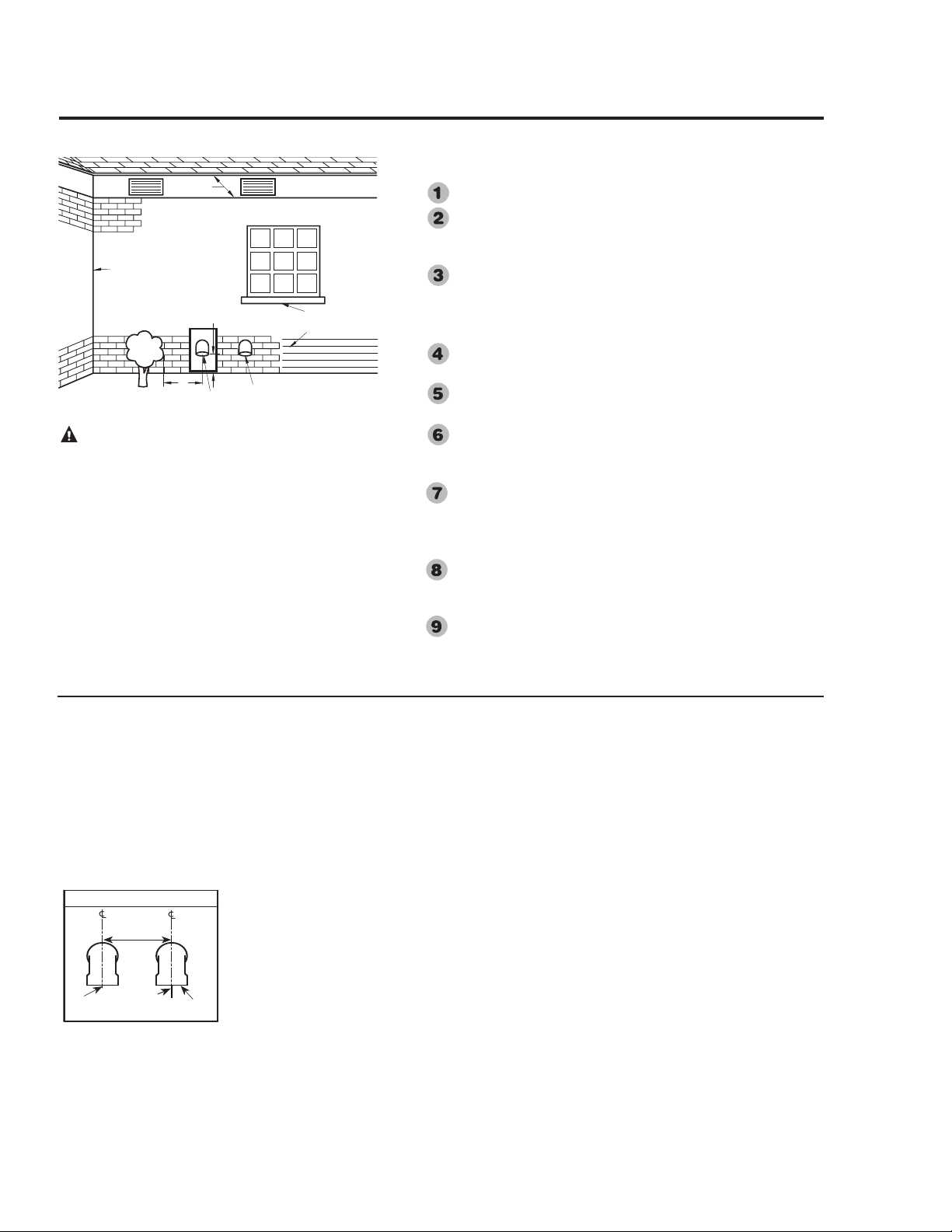
DO NOT install the vent terminal under any patio or deck.
To help prevent moisture from freezing on walls and under
eaves, do not locate the vent terminal on the side of a
building with prevailing winter winds.
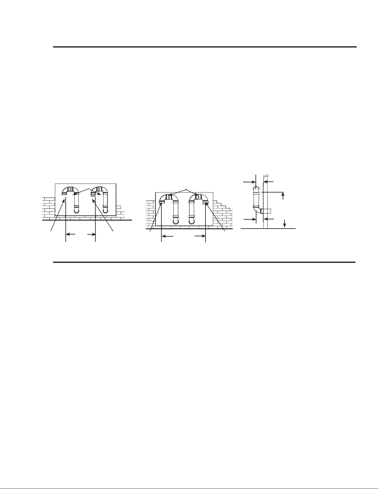
When terminating the vent and combustion air-inlet pipes
through brick or masonry surfaces, the installation of a rust
resistant sheet metal backing plates behind the vent and
combustion air-inlet terminals are recommended.
DO NOT locate the vent terminal too close to shrubbery, as
flue gasses may damage them.
Caulk all cracks, seams and joints within 6 ft. (1.83 m) of
the vent and combustion air-inlet terminals.
Insulate vent pipe exposed to cold conditions (attics, crawl
spaces, etc.) with inflammable material to help prevent
moisture from accumulating in the vent pipe.
Support horizontal sections of the vent and combustion
air-inlet pipe every 4 ft. (1.22 m). DO NOT rigidly secure
the vent system. Provisions must be made to allow for
expansion and contraction of the vent system.
DO NOT install the vent and combustion air-inlet terminals
less than 1 ft. (30 cm) above grade or average snowfall
whichever is greater.
Permanently seal annular openings around the vent and
combustion air-inlet system penetrations using approved
materials to prevent entry of combustion products into the
building.
If soffit vent is too close,
block off and install new vent
at another location
Inside
corner
Caulk
Caulk
12 in. (30.5 cm)
min. above grade or
anticipated snow level
6 ft. (1.8 m) Caulk zone
or to edge of window etc.,
starting within 6 ft. (1.8 m)
Rising moisture will
collect under eves
4 ft.'
(1.22 m)
Vent
Combustion
Air-Inlet
WARNING: Moisture in the flue gas will condense as it
leaves the vent terminal. In cold weather this condensate can
freeze on the exterior wall, under the eaves and on
surrounding objects. Some discoloration to the exterior of
the building is to be expected. However, improper location or
installation can result in severe damage to the structure or
exterior finish of the building
19
Read these instructions thoroughly and make
sure you understand all steps and procedures
before proceeding with the installation.
Determine the locations for the vent and com-
bustion air-inlet terminals then make two (2)
holes through the exterior wall to accommodate
the vent and combustion air-inlet pipes.
• Maintain a minimum horizontal distance of
12 in. (30.5 cm) between the vent and com-
bustion air- inlet terminal centerlines.
Insert lengths of vent and combustion air-inlet
pipes through the wall as shown.
• Allow sufficient length of pipe to extend
beyond the exterior wall of the building for
attachment of the vent and combustion air-
inlet terminals.
Place the supplied 1/2 in. (1.3 cm) mesh metal
screens inside each terminal fitting.
NOTICE: For cold climates the screens may
be removed.
Connect the terminals to the vent and combus-
tion air-inlet pipes which are extending out of
the building.
• Ensure that the back of the supplied termi-
nals are flush with the outside wall surface.
Complete the installation of the remainder of
the vent system and attach it to the vent connec-
tor fitting on the water heater’s blower assem-
bly.
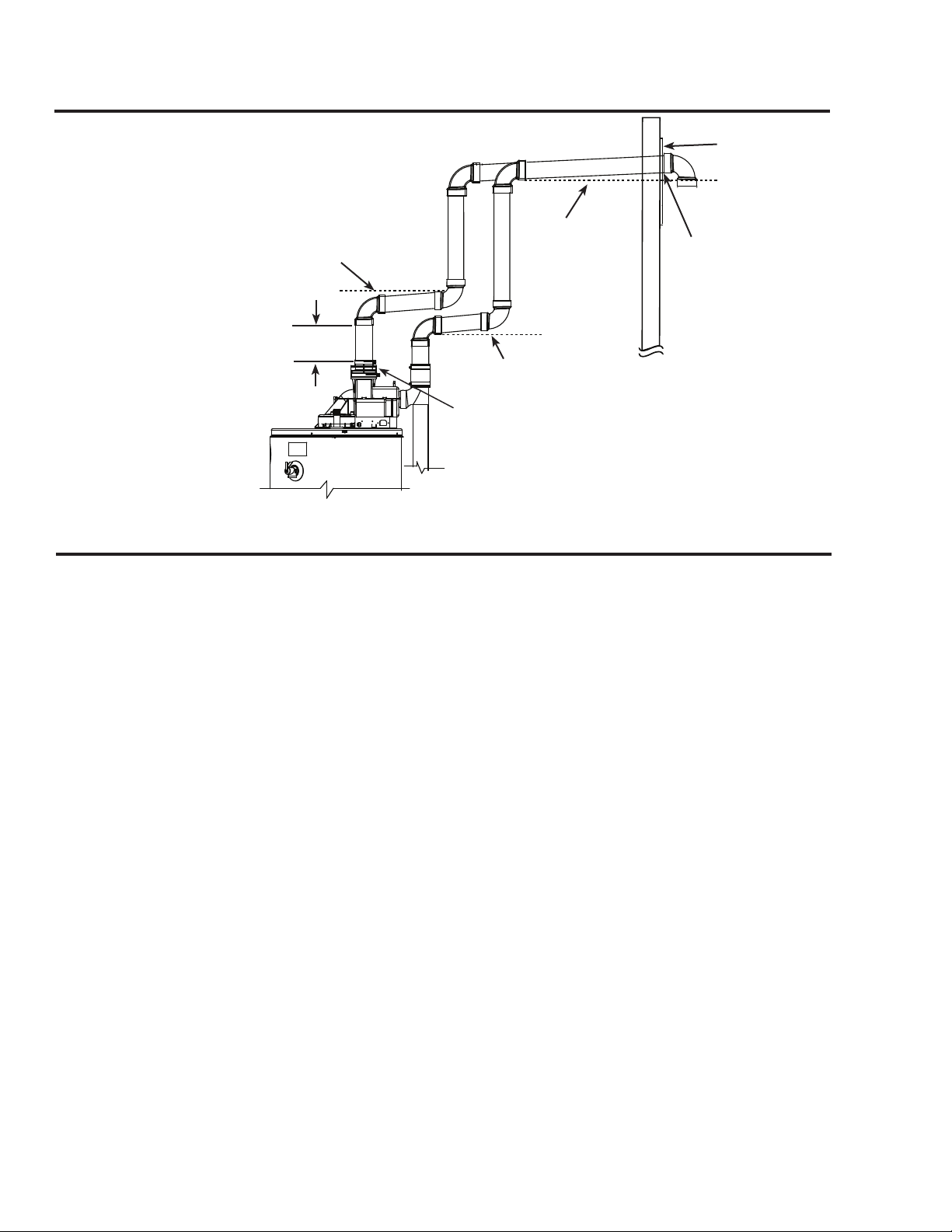
• Horizontal lengths of the vent system
must slope downward a minimum of
1/8 in. per foot (10 mm per m);
IMPORTANT: When the vent system cannot
be sloped away from the water heater or, if the
vent system has vertical section(s), then all hori-
Horizontal Vent and Combustion Air-Inlet Terminal
Installation
Vent Terminal Location Considerations
12 in.
(30.5cm) Min.
Wind Vane
Exhaust Vent
Terminal
Combustion Air-
Inlet Terminal
Installing the Water Heater
20
zontal sections must slope upwards a minimum of
1/8 in. per foot (10 mm per m);
DO NOT use unequal diameters of pipe and fit-
tings for the vent and combustion air-inlet systems
except as defined previously
NOTICE: The difference between the vent and
combustion air-inlet system equivalent lengths
must be no greater than 5 ft. (1.5 m).
Complete the installation of the remainder of the
combustion air-inlet system and attach it to the
combustion air-inlet connector fitting on the water
heater’s combustion air-inlet tube assembly.
Support vertical and horizontal lengths of the vent
and combustion air-inlet systems as previously
mentioned.
For 75 Gallon Power Direct Vent Models
ONLY:
These water heater models are supplied with
two (2) vent and combustion air-inlet termination
restrictors. These restrictors help the water heater
achieve peak efficiency when the water heater is
installed using 3 in. (7.6 cm) diameter pipe at the
minimum equivalent vent and combustion air-inlet
lengths of 8 ft. (2 m).
IMPORTANT: Do not install the termination
restrictors in equivalent vent and/or combustion
air-inlet lengths longer than 8 ft. (2 m) or on any
other Power Direct Vent model.
NOTICE: Termination Restrictors supplied for
use with 75 Gallon models ONLY.
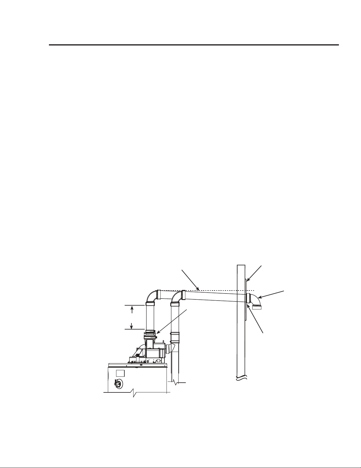
Horizontal Vent and Combustion Air-Inlet Terminal Installation
continued -
2 ft. x 2 ft. (60 cm x 60 cm)
Sheet Metal Shield on Brick or
Masonry Walls
Outside of
Building
Terminals with 1/2 in. (1.3 cm)
Mesh Protective Screens Inside
and Termination Restrictors
Inside.
Note: Termination Restrictors
used on 75 Gallon
models ONLY.
Inside of
Building
Rear of Termination
Flush with Outside
of Wall
-B-
-A-
-B-
d
.008
d
.010
Horizontal Vent and Combustion Air-Inlet
Terminal Installation
Slope horizontal pipe downward 1/8
in. per foot (10 mm per m) min.
Min 1 ft.
(30.5 cm)
Optional -
Condensate
Management Drain
Port*
*See Condensate Management Section for
additional information about optional piping.
21
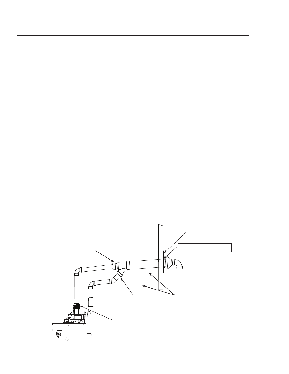
Read these instructions thoroughly and make
sure you understand all steps and procedures
before proceeding with the installation.
Determine the locations for the vent and
combustion air-inlet terminals then make
two (2) holes through the exterior wall to
accommodate the vent and combustion air-inlet
pipes.
• Maintain a minimum horizational distance
of 1 ft. (30.5 cm) between the vent and
combustion air- inlet terminal centerlines.
• Maintain a minimum distance from the
vent and combustion air-inlet terminals of
not less than 1 ft. (30.5 cm) above grade or
average snowfall whichever is greater.
Insert lengths of vent and combustion air-inlet
pipes through the wall as shown.
• Allow sufficient length of pipe to extend
beyond the exterior wall of the building for
attachment of the vent riser assemblies as
shown.
Place the supplied 1/2 in. (1.3 cm) mesh metal
screens inside each terminal fitting.
NOTICE: For cold climates the screens may
be removed.
Connect the vent riser assemblies to the vent
and combustion air-inlet pipes which are
extending out of the building.
• Ensure that the back of the 90° elbows
are flush with the outside wall surface
and that the vent and combustion air-inlet
terminations of the vent risers are parallel
with the outside wall.
IMPORTANT: Remember to include the
additional 90° elbows and vertical height of
vent and combustion air-inlet pipes of the vent
riser when calculating the maximum equivalent
vent and combustion air-inlet system lengths.
The maximum equivalent vent and combustion
air-inlet system lengths must be as specified by
Table 1 or 2.
• The vent and combustion air-inlet
terminations are not included in the
equivalency calculations.
Horizontal Vent and Combustion Air-Inlet Alternate Vent Riser Terminal
Installation
(40, 50, & 65 Gallon Models ONLY)
Alternate Horizontal Vent and Combustion Air-Inlet Terminal Installation
Raise horizontal pipe upwards 1/8 in. per
foot (10 mm per m) min.
Rear of Termination
Flush with Outside
of Wall
Outside of
Building
Inside of
Building
Raise horizontal pipe
upwards 1/8 in. per foot
(10 mm per m) min.
Min 1 ft.
(30.5 cm)
Raise horizontal
pipe upwards 1/8 in.
per foot (10 mm per
m) min.
Optional - Condensate Management
Drain Port*
*See Condensate Management Section for
additional information about optional piping.
2 ft. x 2 ft. (60 cm x 60 cm)
Sheet Metal Shield on Brick or
Masonry Walls
22
Horizontal Vent- Alternate Concentric Terminal Installation: Contact
Manufacturer's National Service Department for Kit information, see "If You Need
Service" section.
Read these instructions thoroughly and make
sure you understand all steps and procedures
before proceeding with the installation.
Determine the location for the concentric termi-
nal then make a 5 in. (12.7 cm) hole through the
exterior wall.
Disassemble the concentric terminal assembly.
• Note: The concentric terminal assembly
consists of an inner, straight vent pipe, an
outer, straight combustion air-inlet pipe, a
Wye tting and rain cap.
The concentric terminal assembly is designed to
accept 3 in. (7.6 cm) diameter pipe.
If 2 in. (5.1 cm) diameter pipe is used:
• Then either 2 in. x 3 in. (5.1 cm x 7.6 cm)
pipe increasers,
• Or ush bushings must be installed to the
vent and combustion air-inlet connections
of the terminal assembly.
• DO NOT use the concentric terminal
assembly with 4 in. (10.2 cm) vent and
combustion air-inlet systems.
From inside the building, insert the outer,
straight combustion air-inlet pipe through the
wall so that the rear of the rain cap when in-
stalled sits ush with the outside wall.
NOTICE: The concentric terminal assembly
may be reduced in length as follows:
• Measure for desired installation length then
cut the outer, straight combustion air-inlet
pipe accordingly but not less than 12 in.
(30 cm).
Installing the Water Heater
12 in.
(30.5 cm) min.
Terminal assemblies to be parallel to wall.
Front View
Option 2
12 in.
(30.5 cm) min.
Terminal assemblies to be parallel to wall.
Front View
Option 1
*
*
* Clearance is equal
and parallel to wall
Side View
Termination Openings -
12 in. (30.5 cm) min. above grade
or anticipated snow level
Short piece of pipe
Short piece of pipe
Complete the installation of the remainder of the
vent system and attach it to the vent connector
fitting on the water heater's blower assembly.
• Horizontal sections of the vent system
must slope downward toward the water
heater a minimum of 1/8 in. per foot
(10 mm per m).
DO NOT use unequal diameters of pipe and
fittings for the vent and combustion air-inlet
systems except as defined previously
NOTICE: The difference between the vent
and combustion air-inlet system equivalent
lengths must be no greater than 5 ft. (1.5 m).
Complete the installation of the remainder of
the combustion air-inlet system and attach it
to the combustion air-inlet connector fitting
on the water heater's combustion air-inlet tube
assembly.
Support vertical and horizontal lengths of
the vent and combustion air-inlet systems as
previously mentioned.
Exhaust
Vent
Terminal
Exhaust
Vent
Terminal
Combustion
Air-Inlet
Terminal
Combustion
Air-Inlet
Terminal
23
-B-
-A-
-B-
d
.008
d
.010
Horizontal Vent - Concentric Terminal Installation
Rear of Rain Cap Flush
with Outside of Wall
Outside of
Building
Inside of
Building
Raise horizontal pipe upwards 1/8 in. per
foot (10 mm per m) min.
Combustion Air-Inlet
System
3 in. (7.6 cm)
Vent
System
3 in. (7.6 cm)
Optional - Condensate
Management Drain
Port*
*See Condensate Management Section for
additional information about optional piping.
• Measure and cut the straight inner vent
pipe of the concentric terminal assembly
so it is 13 in. (5.1 cm) longer in length
than the outer, straight combustion air-inlet
pipe.
• Ensure that there is no insulation or debris
in the pipe.
Assemble the vent pipe assembly.
• Clean and cement the rain cap to the inner,
straight vent pipe.
• From the outside, slide the vent pipe with
rain cap assembly through the combustion
air-inlet pipe until the rear of the rain cap
is ush with the outside wall.
• Clean and cement the rain cap to the com-
bustion air-inlet pipe.
• Clean and cement a 3 in. (7.6 cm) diam-
eter, SDR 35, PVC, 90°, 1/4 standard bend
elbow to the rain cap. See below.
From the inside, clean and cement the Wye t-
ting to the vent and combustion air-inlet pipes
of the termination assembly.
Complete the installation of the remainder
of the vent system and attach it to the vent
connector tting on the water heater’s blower
assembly.
IMPORTANT: Raise all horizontal sections
upwards a minimum of 1/8 in. per foot
(10 mm per m). See below.
DO NOT use unequal diameters of pipe and
ttings for the vent and combustion air-inlet
systems except as dened previously
NOTICE: The difference between the vent
and combustion air-inlet system equivalent
lengths must be no greater than 5 ft.
(1.5 m).
Complete the installation of the remainder of
the combustion air-inlet system and attach it
to the combustion air-inlet connector tting
on the water heater’s combustion air-inlet tube
assembly.
Support vertical and horizontal lengths of the
vent and combustion air-inlet systems as previ-
ously mentioned.
IMPORTANT: Ensure that all the coupling
clamps are tight before allowing the water
heater to operate.
2 ft. x 2 ft. (60 cm x 60 cm)
Sheet Metal Shield on Brick
or Masonry Walls

Read these instructions thoroughly and make
sure you understand all steps and procedures
before proceeding with the installation.
Determine the locations for the vent and com-
bustion air-inlet terminals then make two (2)
holes through the roof and interior ceiling(s) to
accommodate the vent and combustion air-inlet
pipes.
• Maintain a minimum horizontal distance
of 12 in. (3.5 cm) between the vent and
combustion air-inlet terminals.
Assemble the vent pipe assembly.
Install the vent system and attach it to the vent
connector tting on the water heater’s blower
assembly.
Horizontal lengths of the vent system must
slope towards the water heater a minimum of
1/8 in. per foot (10 mm per m).
Install the combustion air-inlet system and
attach it to the combustion air-inlet connector
tting on the water heater’s combustion air-inlet
tube assembly.
• Support vertical and horizontal lengths of
the vent and combustion air-inlet systems
as previously mentioned.
Determine the vent and combustion air-inlet
terminal heights and cut the pipe accordingly.
• Insert lengths of vent and combustion
air-inlet pipes through the ceiling wall as
shown.
• Install adequate ashing where the vent and
combustion air-inlet pipes pass through the
roof.
• Connect a short piece of pipe approxi-
mately 3 in. (7.6 cm) to the terminals and
elbows.
Place the supplied 1/2 in. (1.3 cm) mesh metal
screens inside each terminal tting then connect
a short piece of pipe approximately 3 in.
(7.6 cm) between the terminals and elbows.
NOTICE: For cold climates the screens may
be removed.
For 75 Gallon Power Direct Vent Models
ONLY:
These water heater models are supplied with
two (2) vent and combustion air-inlet termina-
tion restrictors. These restrictors help the water
heater achieve peak efciency when the water
heater is installed using 3 in. (7.6 cm) diameter
pipe at the minimum equivalent vent and com-
bustion air-inlet lengths specied in Table 2.
IMPORTANT: Do not install the termination
restrictors in equivalent vent and/or combustion
air-inlet lengths longer than 8 ft. (2 m) or on any
other Power Direct Vent model.
NOTICE: Termination Restrictors supplied
for use with 75 Gallon models ONLY.
Installing the Water Heater
24
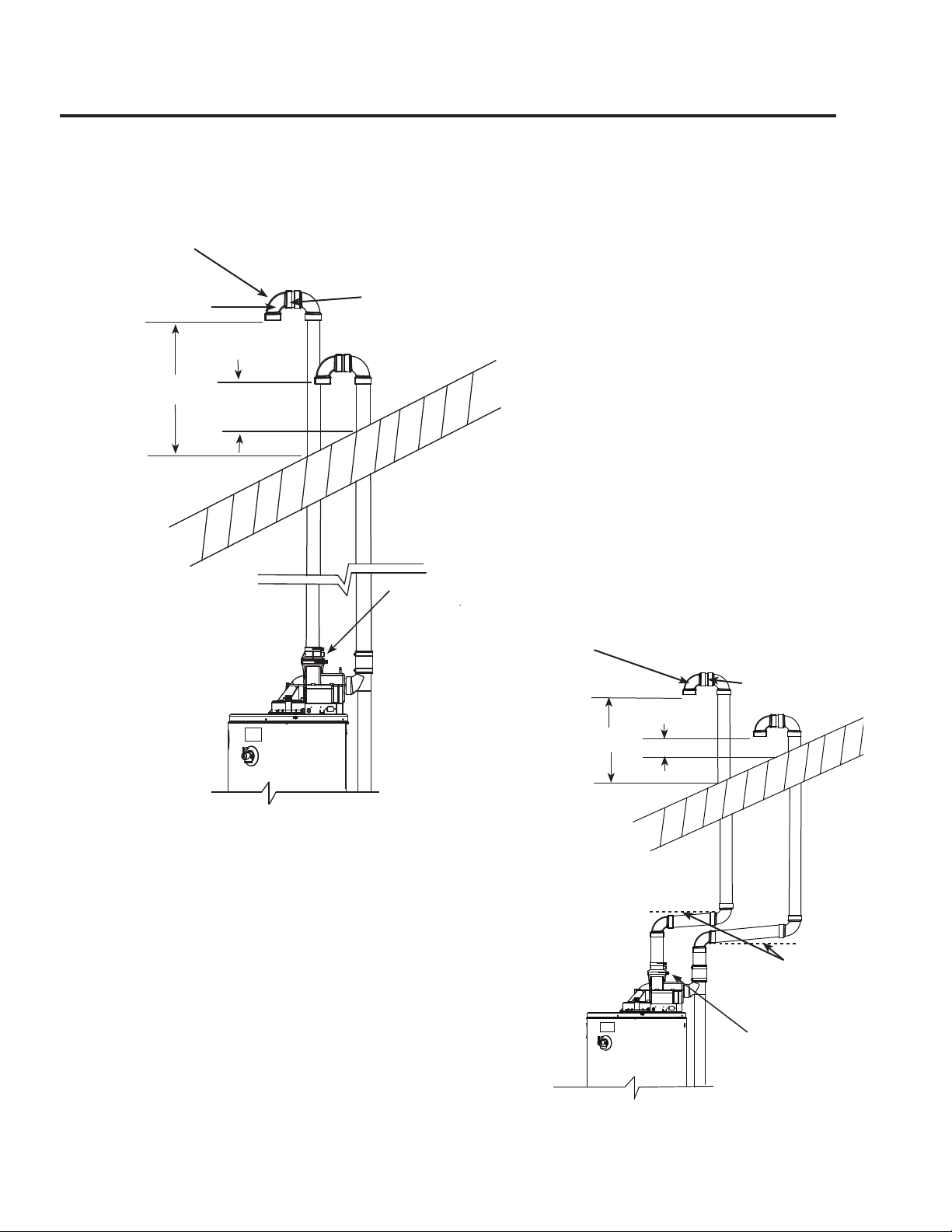
Vertical Vent and Combustion Air-Inlet Installation
The location of the vent and combustion air-inlet terminals depends on the following minimum clear-
ances and considerations.
Minimum 12 in. (30.5 cm) above roof.
Minimum 12 in. (30.5 cm) above anticipated snow level.
Maximum 24 in. (61cm) above roof level without additional support for vent.
Four (4) ft. (1.22 m) from any gable, dormer or other roof structure with building interior
access (i.e., vent, window, etc.).
Ten (10) ft. (3.05m) from any forced air inlet to the building. Any fresh or make-up air inlet
such as a dryer or furnace area is considered to be a forced air inlet.
Maintain a minimum horizontal distance of 12 in. (30.5 cm) between the vent and combus-
tion air-inlet terminal centerlines.
Maintain a minimum distance from the vent and the combustion air-inlet terminals of not less
than 12 in. (30.5 cm) above grade or average snowfall, whichever is greater.
25
IMPORTANT: The vent terminal must not
terminate below the combustion air-inlet terminal.
-B-
-A-
-B-
d
.008
d
.010
#
Min. 12 in.
(30.5 cm) Above Roof
or Anticipated Snow
Level; which
ever is highest
and
Max. 24 in. (61 cm)
Above Roof
(Without Additional
Support)
Terminals with 1/2 in. (1.3 cm) Mesh
Protective Screens and Termination
Restrictors Inside.
Note: Termination Restrictors used on
75 Gallon models ONLY
Exhaust Vent and /or Combustion Air-Inlet Pipe Through Roof
Elbow
Short Piece of Pipe
Exhaust Vent
#
Combustion Air-Inlet
-B-
-A-
-B-
d
.008
d
.010
Alternate Vent and /or Combustion Air-Inlet Pipe Through Roof
Exhaust Vent
Short Piece of Pipe
Combustion Air-Inlet
Slope 1/8 in. per foot
(10 mm per m) towards
the water heater
#
#
Min. 12 in.
(30.5 cm) Above Roof
or Anticipated Snow
Level; which
ever is highest
and
Max. 24 in. (61 cm)
Above Roof
(Without Additional
Support)
#
#
Terminals with 1/2 in. (1.3 cm) Mesh
Protective Screens Inside.
Optional - Condensate Management
Drain Port*
Optional - Condensate Man-
agement Drain Port*
*See Condensate Management Section for addi-
tional information about optional piping.
*See Condensate Management Section for
additional information about optional piping.

Read these instructions thoroughly and make sure you
understand all steps and procedures before proceeding
with the installation.
Determine the location for the concentric terminal
then make a 5 in. (12.7 cm) hole through the roof and
interior ceiling(s) to accommodate the terminal, vent
and combustion air-inlet system pipes and install a
weather-seal boot/ashing (not supplied) for 4 -1/2 in.
(12.4 cm) PVC pipe.
The concentric terminal assembly is designed to
accept 3 in. (7.6 cm) diameter pipe. If 2 in. (5.1 cm)
diameter pipe is used
• Then either 2 in. x 3 in. (5.1 cm x 7.6 cm) pipe
increasers
• Or ush bushings must be installed to the vent
and combustion air-inlet connections of the
terminal assembly.
• DO NOT use the concentric terminal assembly
with 4 in. (10.2 cm) vent and combustion air-inlet
systems.
Disassemble the concentric terminal assembly.
• Note: The concentric terminal assembly consists
of an inner, straight vent pipe, an outer, straight
combustion air-inlet pipe, a Wye tting and rain
cap.
From inside the building, insert the outer, straight
combustion air-inlet pipe through the weather-seal
boot ashing so that the height from the roof to the
rear of the rain cap when installed is as specied in the
diagram.
NOTICE: The concentric terminal assembly may
be reduced in length as follows:
• Measure for desired installation length then
cut the outer, straight combustion air-inlet pipe
accordingly but not less than 12 in. (30 cm).
• Measure and cut the straight inner vent pipe of
the concentric terminal assembly so it is 13 in.
(5.1 cm) longer in length than the outer, straight
combustion air-inlet pipe.
• Ensure that there is no insulation or debris in the
pipe.
Assemble the vent pipe assembly.
• Clean and cement the rain cap to the inner,
straight vent pipe.
From the outside, slide the vent pipe with rain cap
assembly through the combustion air-inlet pipe until
the rain cap if fully seated on the pipe.
• Clean and cement the rain cap to the combustion
air-inlet pipe.
• Clean and cement a 3 in. (7.6 cm) diameter, SDR
45, PVC, 90°, 1/4 standard bend elbow to the rain
cap.
• Clean and cement a short, straight section of 3 in.
(7.6 cm) diameter, straight pipe to the 90° street
elbow.
Vertical Vent - Alternate Concentric Terminal Installation: Contact
Manufacturer's National Service Department for Kit information, see "If You Need Service"
section.
Installing the Water Heater
26
The location of the vent and combustion air-inlet terminal depends on the following minimum clearances and consid-
erations.
Minimum 12 in. (30.5 cm) above roof.
Minimum 12 in. (30.5 cm) above anticipated snow level.
Maximum 24 in. (61 cm) above roof level without additional support for vent.
Four (4) ft. (1.22 m) from any gable, dormer or other roof structure with building interior access (i.e., vent,
window, etc.).
Ten (10) ft. (3.05 m) from any forced air inlet to the building. Any fresh or make-up air inlet such as a
dryer or furnace area is considered to be a forced air inlet.
NOTICE: All pipe, fittings, solvent cement, primers and procedures must conform to American National
Standards Institute and American Society for Testing and Materials (ANSI/ASTM)standards.
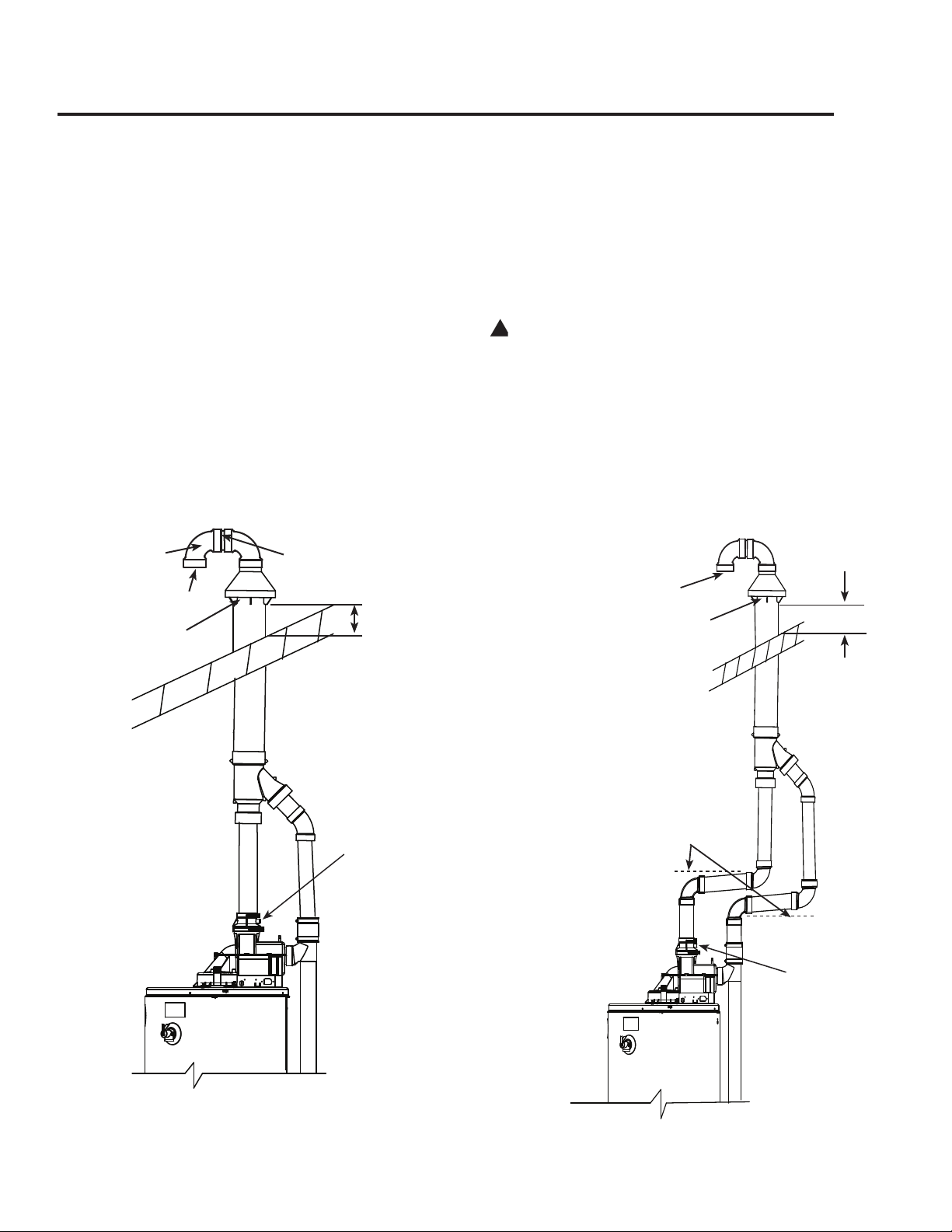
-B-
-A-
-B-
d
.008
d
.010
Vent
#
27
-B-
-A-
-B-
d
.008
d
.010
Vent
Combustion Air-Inlet
Alternate Concentric Vent and /or Combustion Air-Inlet Pipe
Through Roof
Slope 1/8 in. per foot
(10 mm per m) towards
the water heater
Combustion Air-Inlet
Elbow
Short Piece of Pipe
Concentric Vent and /or Combustion Air-Inlet Pipe
Through Roof
• Clean and cement a 3 in. (7.6 cm) diameter,
Schedule 40, PVC, 90°, 1/4 standard bend elbow
to the short, straight section of pipe.
From the inside, clean and cement the Wye tting
to the vent and combustion air-inlet pipes of the
termination assembly.
Complete the installation of the remainder of the vent
system and attach it to the vent connector tting on the
water heater’s blower assembly.
• Horizontal lengths of the vent system must slope
towards the water heater a minimum of 1/8 in. per
foot (10 mm per m).
• DO NOT use unequal diameters of pipe and
ttings for the vent and combustion air-inlet
systems except as dened previously.
NOTICE: The difference between the vent and
combustion air-inlet system equivalent lengths must
be no greater than 5 ft. (1.5 m).
Complete the installation of the remainder of the
combustion air-inlet system and attach it to the
combustion air-inlet connector tting on the water
heater’s combustion air-inlet tube assembly.
Support vertical and horizontal lengths of the vent and
combustion air-inlet systems as previously mentioned.
IMPORTANT: Ensure that all the coupling clamps
are tight before allowing the water heater to
operate.
!
WARNING: Do not operate the water
heater with the rain cap and elbows removed or
recirculation of combustion products may occur
and/or the vent and combustion air-inlet systems
could take in water, causing damage to the water
heater. Failure to follow this warning could result
in damage to the unit, improper operation, personal
injury, or death.
#
Min. 12 in.
(30.5 cm) Above Roof
or Anticipated Snow
Level; which
ever is highest
and
Max. 24 in. (61 cm)
Above Roof
(Without Additional
Support)
#
#
Min. 12 in.
(30.5 cm) Above Roof
or Anticipated Snow
Level; which
ever is highest
and
Max. 24 in. (61 cm)
Above Roof
(Without Additional
Support)
Optional - Condensate
Management Drain Port*
Optional -Condensate
Management Drain
Port*
*See Condensate Management Section for
additional information about optional piping.
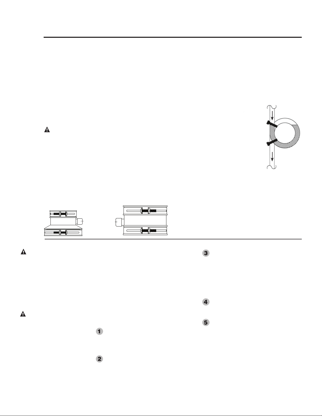
There is no condensate collection and disposal required for
Rheem water heaters under most conditions. Installations
where the vent system length is short or where it runs
through conditioned space in the home, such as basements
or interior walls, do not typically cause condensation
and will not require any condensation disposal methods
regardless of vent pipe slope. The image on page 20
shows the recommended vent pipe slope of no less than
1/8 in. per foot (10 mm per m) away from the water heater.
Any condensation in the venting system will drain toward
the vent termination. The blower pipe coupling features a
capped drain port which is not needed in this case.
CAUTION: Make sure the drain port cap is
securely in place.
There are vent piping configurations, when combined with
certain environmental conditions that can produce enough
condensate to require collection and disposal. When a
slope away from the water heater cannot be achieved
and condensate handling is required in a horizontal vent
system, slope the vent pipe toward the water heater
1/8 in. per foot (10 mm per m) minimum and condensate
management means as follows:
• Remove the cap from vent pipe coupling, drain port
on the blower assembly.
• Connect 1/2 in. I.D, flexible, PVC (or equivalent
material), clear tubing to the drain port.
Notice: The tubing must be of sufficient length to
reach a floor drain, outside the building or other
required condensate disposal termination requirements
(Refer to local codes).
• Loop the drain tube so that it has a circular trap and
secure the top and
bottom of the loop with
wire ties or plastic zip
ties as shown. DO NOT
restrict any portion of
the drain tube. The
loop and all sections
of the tube must not be
restricted or collasped.
• Fill the drain tube
with water so that no
combustion gases might
vent into the room.
• Route the drain tube to a floor drain or outside the
building or refer to local codes for any condensation
requirements..
Installing the Water Heater
All joints in the vent piping must be properly
sealed and the following materials are recom-
mended:
PVC materials should use ASTM D2564 grade
cement.
CPVC materials should use ASTM F493 grade
cement.
ABS materials should use ASTM D2235 grade
cement.
Cleaner-Primer and Medium Body Solvent
Cement:
Cut pipe end square, remove jagged edges
and burrs. Chamfer end of pipe, then clean
fitting socket and pipe joint area of all dirt,
grease or moisture.
After checking pipe and socket for proper
fit, wipe socket and pipe with cleaner-prim-
er. Apply a liberal coat of primer to inside
surface of socket and outside of pipe. Do not
allow primer to dry before applying cement.
Apply a thin coat of cement evenly in the
socket. Quickly apply a heavy coat of
cement to the pipe end and insert pipe into
fitting with a slight twisting motion until it
bottoms out.
NOTICE: Cement must be fluid; if not,
recoat.
Hold the pipe fitting for 30 seconds to pre-
vent the tapered socket from pushing the
pipe out of the fitting.
Wipe all excess cement from the joint with a
rag. Allow 15 minutes before handling. Cure
time will vary according to fit, temperature
and humidity.
NOTICE: Stir the solvent cement frequently
while using. Use a natural bristle brush or
the dauber supplied with the can.
NOTICE: This unit is equipped with a
Flammable Vapor Sensor. Do not apply
power until enough time has passed to allow
the vapors from the primer and cement to
dissipate.
Cementing Joints
WARNING: DANGER OF
FIRE OR BODILY INJURY -
Solvent cements and primers
are highly flammable. Provide
adequate ventilation and do
not assemble near heat source
or open flame. Do not smoke.
Avoid skin or eye contact.
Observe all cautions and
warnings on material
containers.
28
Condensate Management - Optional Piping
CAUTION:
For proper installation:
DO NOT use solvent cement
that has become curdled,
lumpy or thickened.
DO NOT thin solvent cement.
Observe shelf precautions
printed on the containers.
For applications below 32°F
(0°C) use only low temperature
type solvent cement.
Appropriate solvent and
cleaner must be used for the
type of pipe used (PVC, CPVC
or ABS).
Cap
Cap
Water Filled
Wire or Zip Ties
To Floor Drain
From Drain Port
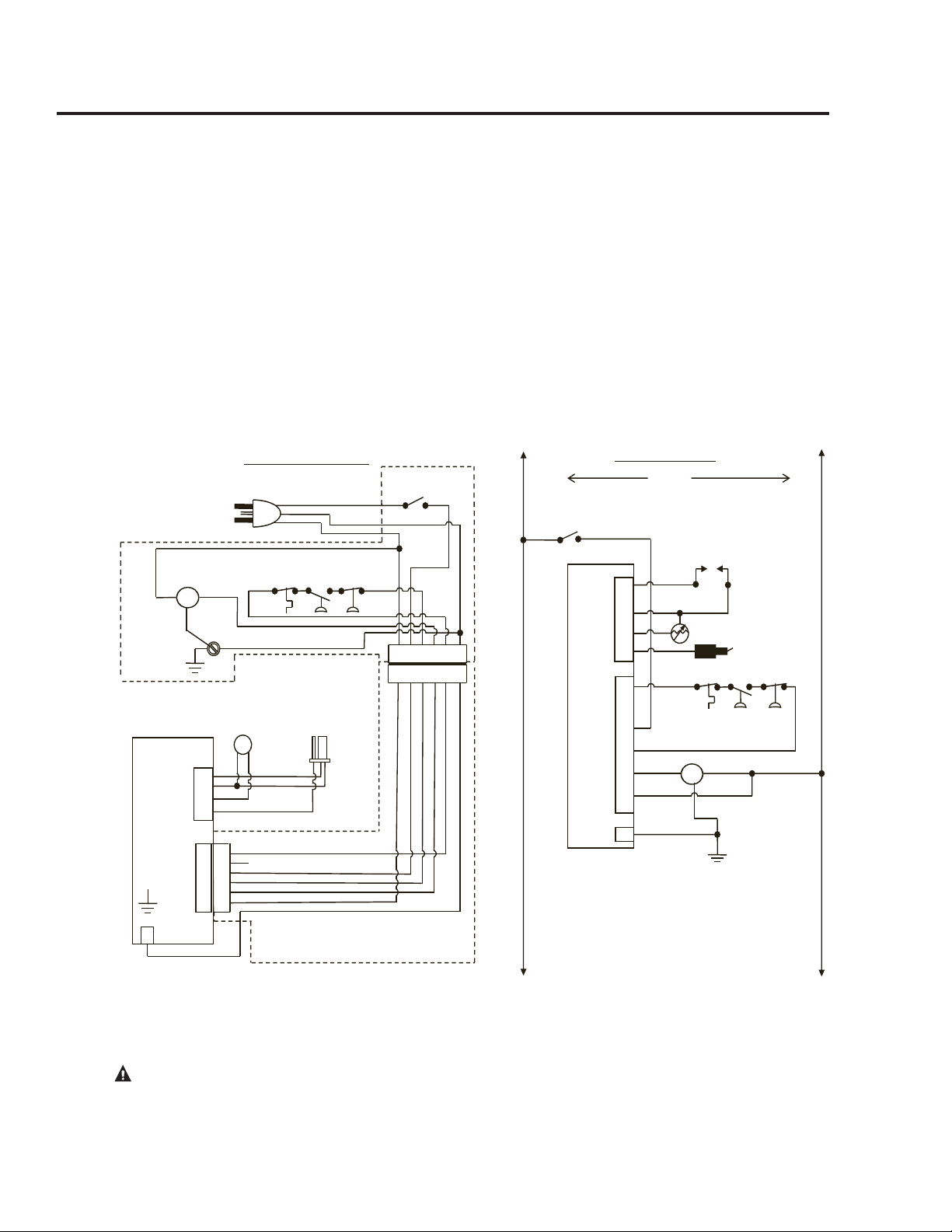
Wiring
If local codes permit, the water heater may be
connected to electric service with the power
cord provided (DO NOT use an extension
cord). A grounding receptacle is required.
If local codes do not permit the use of cord
connections, a 120 V, 50/60 Hz power supply,
with suitable disconnecting means, must be
connected to the black and white leads in the
blower assembly.
The water heater must be electrically grounded
in accordance with local codes, or, in the
absence of local codes, in accordance with
latest edition of the National Electric Code
ANSI/NFPA No. 70. Refer to the figures below
for water heater internal wiring.
1
2
3
4
5
6
J2
1
2
3
4
1
2
3
4
5
6
GAS VALVE
SOUPAPE DE GAZ
INTELLI-VENT ELECTRONIC CONTROL
CONTRÔLE ÉLECTRONIQUE INTELLI-VENT
BK
W
W
W
BK
1 2 3 4 5 6
1 2 3 4 5 6
W BK R Y BL G
WIRE HARNESS THAT RUNS FROM BLOWER ASSEMBLY
TO WIPER CONTROL GAS VALVE
FAISCEAU DE CÂBLAGE ENTRE L’ENSEMBLE DU
SOUFFLEUR ET LA INTELLI-VENT DE LA SOUPAPE DE
CONTRÔLE DU GAZ
ANY REPLACEMENT IGNITOR CABLE MUST BE RATED AT 250º C
TOUT CÂBLE D’ALLUMAGE DE REMPLACEMENT DOIT ÊTRE
ÉTALONNÉ Á 250º C
120V 50/60 Hz LESS THAN 5 AMPS
IGNITER AND
FLAME SENSOR
ALLUMEUR ET
CAPTEUR DE
FLAMME
FLAMMABLE
VAPOR SENSOR
DÉTECTEUR DE
VAPEUR
INFLAMMABLE
H
G
N
120 VAC PLUG FOR POWERVENT
BLOWER ASSEMBLY
PRISE DE 120 VCA POUR
L’ENSEMBLE DE
SOUFFLEUR D’ÉVENT MÉCHANIQUE
POWER
VENT BLOWER
ASSEMBLY
ENSEMBLE DU
SOUFFLEUR
D’ÉVENT
MÉCANIQUE
BLOWER
SOUFFLEUR
CONTACTEUR À
DÉPRESSION
6 PIN CONNECTOR
CONNECTEUR À
6 BROCHES
W
BK R Y BL G
CONNECTOR DIAGRAM
SCHÉMA DES CONNEXIONS
SCREW
GND VIS
DE MISE
À LA TERRE
H
N
1
2
3
4
5
6
1
2
3
4
GAS VALVE
SOUPAPE DE GAZ
INTELLI-VENT ELECTRONIC CONTROL
CONTRÔLE ÉLECTRONIQE INTELLI-VENT
BK
W
W
W
BK
GND
MOT
120 VAC
H N
SCHEMATIC DIAGRAM
SCHÉMA DE CABLÂGE
BL
N/C
BK
R
W
Y
MOT
BLOWER
SOUFFLEUR
NOTE: IF ANY OF THE ORIGINAL WIRE SUPPLIED WITH THE APPLIANCE
MUST BE REPLACED, IT MUST BE REPLACED WITH A 18 GA, 600 V,
105º C WIRE.
REMARQUE: SI UNE PARTIE QUELCONQUE DU CÂBLAGE ORIGINAL
FOURNI AVEC L’APPAREIL DOIT ÊTRE REMPLACÉE, ELLE DOIT ÊTRE
REMPLACÉE AVEC UN FIL DE CALIBRE 18, 600 VCA, 105º C.
BK = BLACK/NOIR
BL = BLUE/BLEU
G = GREEN/VERT
R = RED/ROUGE
W = WHITE/BLANC
Y = YELLOW/JAUNE
BK
G
W
FV
VAC
SW NO
VAC
SW NC
TEMPERATURE
SWITCH NC
CHANGEMENT DE
TEMPÉRATURE
ON/OFF SWITCH
CONTACTEUR
MARCHE/ARRÉT
IGNITER
ALLUMEUR
FLAMMABLE VAPOR SENSOR
DÉTECTEUR DE VAPEUR INFLAMMABLE
FLAME SENSOR
CAPTEUR DE FLAMME
ON/OFF
SWITCH
CONTACTEUR
MARCHE/ARRÉT
VAC
SW NO
VAC
SW NC
TEMPERATURE
SWITCH NC
CHANGEMENT DE
TEMPÉRATURE
CONTACTEUR
À DÉPRESSION
N/C
GND
BL
BK
R
Y
W
G
AX4944-3
CAUTION! Label all wires prior to disconnection when servicing controls. Wiring errors can cause improper and
dangerous operation. VERIFY PROPER OPERATION AFTER SERVICING!
29
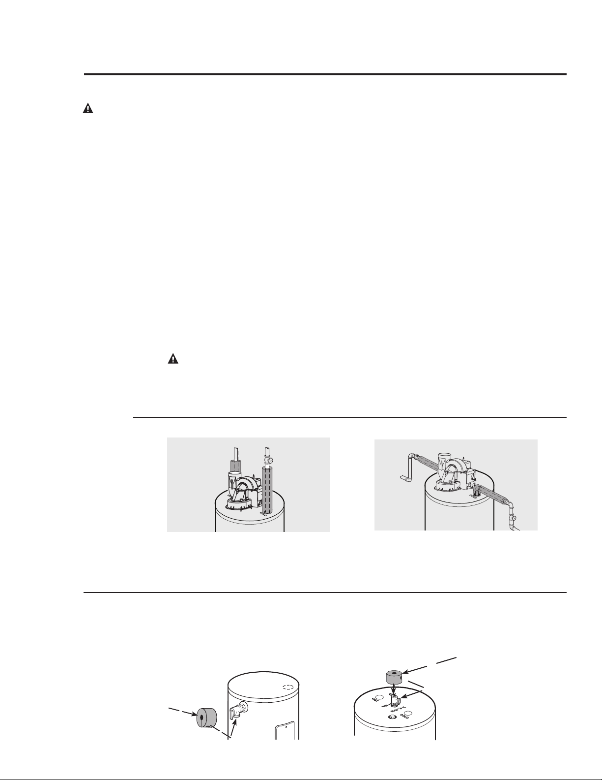
For increased energy efficiency, some water
heaters have been supplied with two 24 in.
(61 cm) long sections of pipe insulation.
Please install the insulation, according to
the illustrations above, that best meets your
requirements.
Typical vertical piping arrangement
Hot and Cold Pipe Insulation Installation
Insulation Blankets
Insulation blankets, available to the general pub-
lic, for external use on gas water heaters are not
necessary. The purpose of an insulation blanket
is to reduce the standby heat loss encountered
with storage tank heaters. This water heater
meets or exceeds the National Appliance Energy
Conservation Act standards with respect to insu-
lation and standby loss requirements making an
insulation blanket unnecessary.
The manufacturer’s warranty does not cover
any damage or defect caused by installation,
attachment or use of any type of energy saving
or other unapproved devices (other than those
authorized by the manufacturer) into, onto or in
conjunction with the water heater. The use of
unauthorized energy saving devices may shorten
the life of the water heater and may endanger
life and property.
The manufacturer disclaims any responsibility
for such loss or injury resulting from the use of
such unauthorized devices.
CAUTION: If local codes require the
application of an external insulation blanket
to this water heater, pay careful attention to
the following so as not to restrict the proper
function and operation of the water heater:
DO NOT cover the operating or warning
labels attached to the water heater or attempt
to relocate them on the exterior of insulation
blanket.
DO NOT apply insulation to the top of the
water heater. This will interfere with the safe
operation of the blower assembly.
DO NOT cover the burner access door, jacket
door, gas control (thermostat) or pressure and
temperature relief valve.
DO NOT apply insulation to the area where
the Flammable Vapor Sensor is located. This
area must be unobstructed so as not to restrict
air flow to the sensor.
Inspect the insulation blanket frequently mak-
ing certain it has not sagged and it is not restrict-
ing the air flow to the Flammable Vapor sensor
located around the lower perimeter of the water
heater jacket. This could result in an unsafe
operating condition.
WARNING: If
local codes require
external
application of
insulation blanket
kits the
manufacturer’s
instructions
included with the
kit must be
carefully followed.
Typical horizontal piping arrangement
(Piping for Top Cap NOT shown)
Installing the Water Heater
30
For increased energy efficiency, this water heater has been supplied with a 2 3/8” section of T&P
insulation. Please install the insulation as shown below.
T&P Insulation Installation
Typical Side Connect T & P Arrangement.
Slip the insulation cover
over the T&P Valve
through the center hole
and align the hole in the
side with the opening of
the T&P Valve.
Ensure the T&P Valve
opening is not obstructed
by the insulation.
Typical Top Connect T & P Arrangement.
Slip the insulation cover
over the T&P Valve
through the center hole
and align the hole in the
side with the opening of
the T&P Valve.
Ensure the T&P Valve
opening is not obstructed
by the insulation.
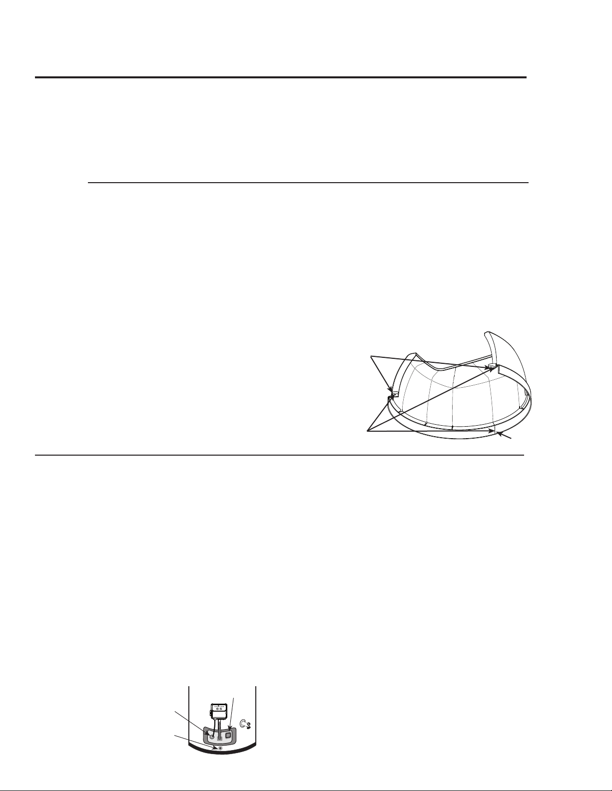
DO
o DO check inlet gas pressure to ensure that it is
within the range specified on the rating plate.
o DO maintain proper clearances to combustibles
as specified on the rating plate.
o DO allow enough time for joint cement vapors to
dissipate BEFORE applying power to the water
heater.
o DO ensure that the venting system complies with
the guidelines found in the Use and Care Manual
and National Fuel Gas Code.
o DO contact a qualified service technician if the
main burner will not stay lit. The burner chamber
is designed to be sealed utilizing a gasket and
tamper resistant screws.
DON’T
o DON’T block or restrict the Flammable Vapor
Sensor located around the lower portion of the
water heater jacket.
o DON’T remove the Burner Access Door unless
absolutely necessary. This should only be done
by a qualified service technician. A new burner
access door gasket must be installed on any
burner access door that has been removed.
o DON’T install this water heater where standing
water may occur. The base of the water heater is
meant to be mounted on a dry surface.
o DON’T allow cleaners, solvents, or other mate-
rials to come into contact with the Flammable
Vapor Sensor.
o DON’T operate the water heater if the sight glass
or burner access door grommet is damaged or
broken.
During Installation of this water heater...........
Flammable
Vapor Sensor
VACATION
VERY
HOT
WARM
A B C
COOLER
HOTTER
Burner Access
Door Grommet
Sight Glass
31
Top Cap Installation (For Certain Models Only)
Read these instructions thoroughly and make
sure you understand all the steps and procedures
before proceeding with the installation.
Carefully remove the Top Cap from the water
heater carton. Install the water heater as speci-
ed per this Use & Care Manual. Note: Also see
information as detailed in “Water Supply Connec-
tions” section.
Locate the small plactic bag containing the three
(3) Dual Lock
®
strips and two (2) sheet metal
screws to be used to attach the Top Cap in the
Use & Care Manual bag. Peel off one side of the
Dual Lock
®
strips and rmly press near the Top
Cap mounting tabs and the inside center front of
the rim on the Top Cap. See diagram for detail.
Peel off the other side of the Dual Lock
®
strips
and place the Top Cap on the top front center of
the water heater ensuring that it is aligned cor-
rectly and properly positioned on top of the water
heater. Press rmly to ensure proper attachment
is made.
Align holes in mounting tabs on the Top Cap with
the holes in the top of the heater then secure the
Top Cap to the water heater with the two (2) #8
sheet metal screws (supplied).
IMPORTANT: Do not over tighten the screws
as this may damage the Top Cap.
3 Dual Lock
®
Strips
2 screws
(mounting
tabs)
Inside Center
Front
Inside
Outside
Top Cap View
Heat Traps
For increased energy efficiency, some water
heaters have been supplied with factory installed
3/4 in. or 1 in. NPT heat trap fittings in the hot
outlet line and cold water inlet line. These heat
trap fittings may require a minimum of one (1)
90°, 3/4 in. or 1 in. NPT elbow and may require
an additional 90°, 3/4 in. or 1 in. NPT elbow or
a 3/4 in. or 1 in. coupling depending on your
model of water heater and installation needs.
See illustration of nipples and heat traps on page
43.

Installation Checklist
A. Water Heater Location
o In a location where the vent and combustion air-
inlet systems will be within the requirements speci-
fied in this manual.
o Indoors and protected from freezing temperatures.
o Proper clearance from combustible surfaces
observed and water heater not installed on carpeted
floor.
o Air supply free of corrosive elements and flam-
mable vapors.
o Provisions made to protect area from water dam-
age.
o Sufficient room to service the water heater.
o Combustible materials, such as clothing, cleaning
materials, rags, etc. clear of the base of the water
heater.
o Flammable vapor sensor is not blocked.
B. Water Supply
o Water heater completely filled with water.
o Air purged from water heater and piping.
o Water connections tight and free of leaks.
C. Gas Supply
o Gas line equipped with shut-off valve, union and
sediment trap.
o Approved pipe joint compound used.
o Soap and water solution used to check all connec-
tions and fittings for possible gas leak.
o Gas Company inspected installation (if required).
D. Relief Valve
o Temperature and Pressure Relief Valve properly
installed and discharge line run to open drain.
o Discharge line protected from freezing.
E. Venting and Combustion Air-Inlet Systems
o Water Heater vented separately from all other
appliances.
o Blower assembly properly installed.
o Proper materials and techniques used in the instal-
lation of the vent and combustion air-inlet systems.
o Vent pipe properly secured to the exhaust connector
of the blower assembly.
o Vent and combination air-inlet systems supported at
required intervals.
o Appropriate minimum clearances observed.
o Precautions taken to prevent moisture damage
around vent termination.
o Vapors from non-metalic pipe cement and primer
have dissipated prior to applying electrical power.
o Combustion Air-Inlet pipe properly secured to the
combustion air-inlet piping tee.
F. Wiring
o Correct power supply (120 VAC).
o Electrical connections tight.
o Water Heater properly grounded and proper polar-
ity observed.
32
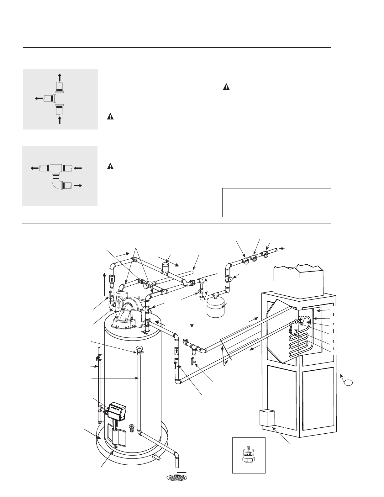
Tee fitting for vertical hot
water supply lines.
Hot water
supply to
house
From HOT
outlet on
water heater
Hot water
supply to
heating
unit
Supplemental Instructions for Gas Water Heaters
Installed in Potable Water/Space Heating Applications
Local codes or plumbing authority requirements may vary from the instructions or diagrams provided
in this manual and take precedent over these instructions.
Tee fitting for horizontal hot
water supply lines.
From HOT
outlet on
water heater
Hot water
supply to
house
Hot water supply
to heating unit
Tee fitting must be installed as shown.
This ensures that any air in the water lines
will be purged through the domestic water
faucets and showers.
DANGER: When this system
requires water for space heating at
elevated temperatures (above 125°F
[52°C.]), a mixing or tempering valve
must be installed in the hot water
supply line to the house in order to
reduce the scald hazard potential.
DANGER: Any piping or components
used in the installation of this water
heater in a combination potable and
space heating application must be
suitable for use with drinking water.
DANGER: If this water heater is
installed in an application intended to
supply domestic hot water needs and
hot water for space heating purposes,
do not connect the heater to an existing
heating unit or components of a heating
system that have previously been used
with a non drinking water system. Toxic
chemicals such as those used for boiler
treatment may be present and will
contaminate the drinking water supply
causing possible health risks. Never
introduce toxic chemicals, such as those
used for boiler treatment, into this
system.
Notice: 50 ft. (15.2 m) maximum
distance from water heater to fan coil
(developed length) is required for
Massachusetts State.
22
Typical Piping Diagram for Combination Potable/Space Heating Installation
Spring loaded check valve in heating unit
hot water supply line and cold water return
line (not supplied with water heater)
NOTE: This check valve is incorporated
in some heating units. Refer to the
installation instructions supplied with
specific heating unit to determine if it is
required.
All water piping shall be insulated in
accordance with Local and State Energy
Code.
Isolation valve in
cold water return line
from heating unit (not
supplied with water
heater)
Nominal 3/4" size mixing or tempering valve
(refer to warning above). Follow mixing or
tempering valve manufacturer’s instructions for
installation of the valve.
Temperature and pressure relief
valve discharge line
Air Handler
Drain valve
(not supplied with
water heater)
Hot water
to space heater
Temperature and Pressure Relief
Valve, tie to location approved by
local code
See diagrams above for proper
pipe application for vertical
or horizontal supply lines.
Isolation valve in hot water supply line
to heating unit (not supplied with water
heater)
3/4" cold water supply
3/4" Tempered
domestic hot water
supply to house.
Gas line to water heater
6 in. (15.2 cm)
Air Gap
2 Gallon Thermal
Expansion Tank (if
required-not supplied
with water heater)
Air vent
Heat Trap
6 in. (15.2
cm) Min.
3/4" Shut-Off Valve (Typ.)
3/4" Check Valve with 1/8" Hole
Pressure Gauge
3/4" Shut-Off Valve (Typ.)
3/4" Shut-
Off Valve
(Typ.)
Hot water coil
All bronze pump.
Check valve
internal in pump.
Air bleed valve.
Water Sample Tap.
T
FAN
ON
OFF
HEAT
COOL
To HVAC Unit.
Electronically controlled pump timer.
Activates every 6 hours for 60 seconds.
Wire to bronze pump.
3/4" HWS & HWR
to Heating Coil.
Minimum of 2 ft. (61 cm) developed
length of 3/4" pipe.
Water heater drain pan installed in
accordance with the Local and State
Code
Water heater to be in accordance with
the Local and State Energy Code
Gas Fired
Water Heater
Flammable Vapor Sensor
Vacuum Relief Valve
(Not Supplied)
If required, install per local codes
and valve manufacturer’s
instructions.
120° F to 130° F
140° F (60° C)
Combination gas control
49° C to 54° C
Combination Potable Water and Space Heating Application
33
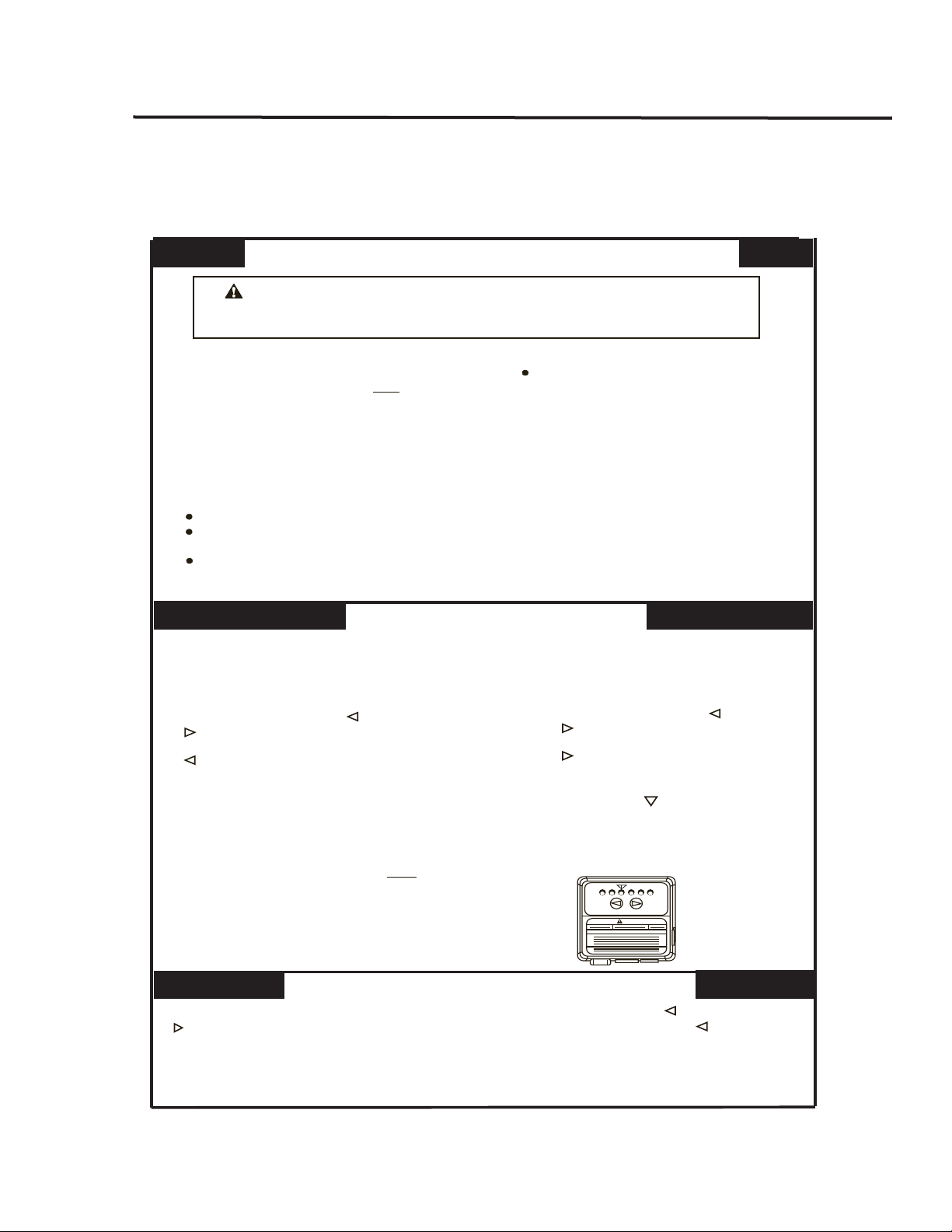
Lighting the Water Heater
Before operating this water heater, be sure to read and follow the instructions on the label pictured below and
all other labels on the water heater, as well as the warnings printed in this manual. Failure to do so can result in
unsafe operation of the water heater resulting in property damage, personal injury, or death. Should you have
any problems reading or following the instructions in this manual, STOP, and get help from a qualified person.
FOR YOUR SAFETY READ BEFORE OPERATING
OPERATING INSTRUCTIONS
TO TURN GAS OFF TO THE APPLIANCE
WARNING:
If you do not follow these instructions and the Use & Care
Manual instructions exactly, a fire or explosion may result causing property
damage, personal injury or loss of life.
If you cannot reach your gas
supplier, call the fire department.
C.
Do not use this appliance if any part has
been under water. Immediately call a
qualified installer or service agency to
replace a flooded water heater. Do not
attempt to repair the unit! It must be
replaced!
Use only your hand to push in the gas
control buttons. Never use tools. If the
control buttons will not push in, don’t try
to repair them, call a qualified service
technician. Force or attempted repair
may result in fire or explosion.
D.
gas supplier’s instructions.
10.
11.
1.
2.
3.
VACATION
WARNING
VERY
HOT
WARM
A B C
COOLER
HOTTER
This appliance does not have a pilot. It is
equipped with an ignition device which auto-
matically lights the burner. Do NOT try to light
the burner by hand.
A.
BEFORE PUTTING THIS APPLIANCE INTO
SERVICE - Smell all around the appliance
area for gas. Be sure to smell next to the
floor because some gas is heavier than air
and will settle on the floor.
B.
Immediately call your gas supplier
from a neighbor’s phone. Follow the
Do not try to light any appliance.
Do not touch any electric switch; do
not use any phone in your building.
WHAT TO DO IF YOU SMELL GAS
Turn off all electrical power to the appliance.
Set the thermostat to the lowest setting by first depressing the COOLER and HOTTER
buttons at the same time and holding for (1) second. Depress the COOLER button
until only the WARM indicator light is lit.
Stop! Read the safety information above
on this label.
Toggle the “ON/OFF” switch located on the
blower assembly to the “OFF” position.
Turn off all electrical power to the appliance.
This appliance is equipped with a Hot
Surface Ignition System which auto-
matically lights the burner. Do NOT open
the inner door of this appliance and try to
light the burner by hand!
Wait five (5) minutes to clear out any gas.
If you smell gas, STOP! Follow “B” in the
safety information above on this label. If
you do not smell gas, go ahead to the next step.
Turn on all electrical power to the appliance.
Toggle the “ON/OFF” switch located on the
blower assembly to the “ON” position.
Set thermostat to the desired temperature
setting by pressing the COOLER and
HOTTER buttons at the same time and
holding them for (1) second. Depress the
HOTTER button until the desired
temperature display setting is lit. The
preferred starting point for temperature
setting is indicated by on the thermostat.
If the appliance will not operate, follow
the instructions “TO TURN OFF GAS TO
APPLIANCE” and call your service
technician or gas supplier.
1.
4.
3.
5.
6.
7.
8.
9.
Set the thermostat to the lowest setting
by pressing the COOLER and HOTTER
buttons at the same time and holding
them for (1) second. Depress the COOLER
button until only the WARM indicator
light is lit.
Toggle the “ON/OFF” switch located on the blower assembly to the “OFF” position.
Toggle the “ON/OFF” switch located on the
blower assembly to the “ON” position.
2.
34
Operating the water heater
Safety Precautions
Do turn off manual gas shut-off valve if water heater
has been subjected to over heating, fire, flood, physi-
cal damage or if the gas supply fails to shut off.
Do Not turn on water heater unless it is completely
filled with water.
Do Not turn on water heater if cold water supply
shut-off valve is closed.
Do Not allow combustible materials such as newspa-
per, rags or mops to accumulate near
water heater.
Do Not store or use gasoline or other flammable
vapors and liquids, such as adhesives or paint thinner,
in vicinity of this or any other appliance.
If such flammables must be used, open doors
and windows for ventilation, and all gas burning
appliances in the vicinity should be shut off including
their pilot burners, to avoid vapors lighting.
NOTICE: Flammable vapors can be drawn by air
currents from surrounding areas to the water heater.
If there is any difficulty in understanding or following
the Operating Instructions or the Care and Cleaning
section, it is recommended that a qualified person or
serviceman perform the work.
CAUTION: Hydrogen gas can be produced in a hot water system served by this water heater that has not been
used for a long period of time (generally two weeks or more). HYDROGEN GAS IS EXTREMELY
FLAMMABLE!! To dissipate such gas and to reduce risk of injury, it is recommended that the hot water faucet
be opened for several minutes at the kitchen sink before using any electrical appliance connected to the hot water
system. If hydrogen is present, there will be an unusual sound such as air escaping through the pipe as the water
begins to flow. Do not smoke or use an open flame near the faucet at the time it is open.
!
DANGER: Hotter water
increases the Potential
for Hot Water SCALDS
.
Households with small
children, disabled, or elderly
persons may require a 120°F
(49°C) or lower combination
gas control (thermostat)
setting to prevent contact
with unsafe water
temperatures.
Water Temperature Setting
The temperature of the water in the water
heater can be regulated by pressing the
buttons on the front of the combination
gas control (thermostat).
Safety and energy conservation are factors
to be considered when selecting the water
temperature setting of the water heater’s
combination gas control (thermostat). The
lower the temperature setting, the greater
the savings in energy and operating costs.
To comply with safety regulations, the
combination gas control (thermostat) was
set at its lowest setting before the water
heater was shipped from the factory. The
recommended starting point temperature is
120°F (49°C).
Water temperatures above 125°F (52°C)
can cause severe burns or death from
scalding. Be sure to read and follow the
warnings outlined in this manual and on
the label located on the water heater near
the combination gas control (thermostat).
Mixing valves are available for reducing
point of use water temperature by mixing
hot and cold water in branch water lines.
Contact a licensed plumber or the local
plumbing authority for further informa-
tion.
The chart on the next page may be used
as a guide in determining the appropriate
water temperature for your home.
Operating Procedure
This water heater is equipped with a hot
surface ignitor to light the main burner.
There is no pilot light to be lit, but on initial
start-up, it is recommended that the outer
door be removed (leave inner door in place
for safety) to view through the sight glass if
the hot surface ignitor and main burner are
operating properly.
Once filled with water, it is only neces-
sary to plug the power cord in and make
sure the “ON/OFF” switch located on the
blower assembly is in the “ON” position to
put the water heater into operation. Within
seconds the hot surface ignitor should heat
up, then the gas valve should open and the
main burner ignite. After the main burner
ignites, replace the outer door. If no main
burner flame is established, the combina-
tion gas control will go through three trials
for ignition before going into a lock-out.
A warning light will alert the user of this
lock-out condition. If this happens, refer to
“Troubleshooting Guide.”
TO SHUT OFF WATER HEATER – Turn
switch located on the side of the blower
assembly to the “OFF” position. See dia-
gram on page 43 for location of blower
assembly.
35
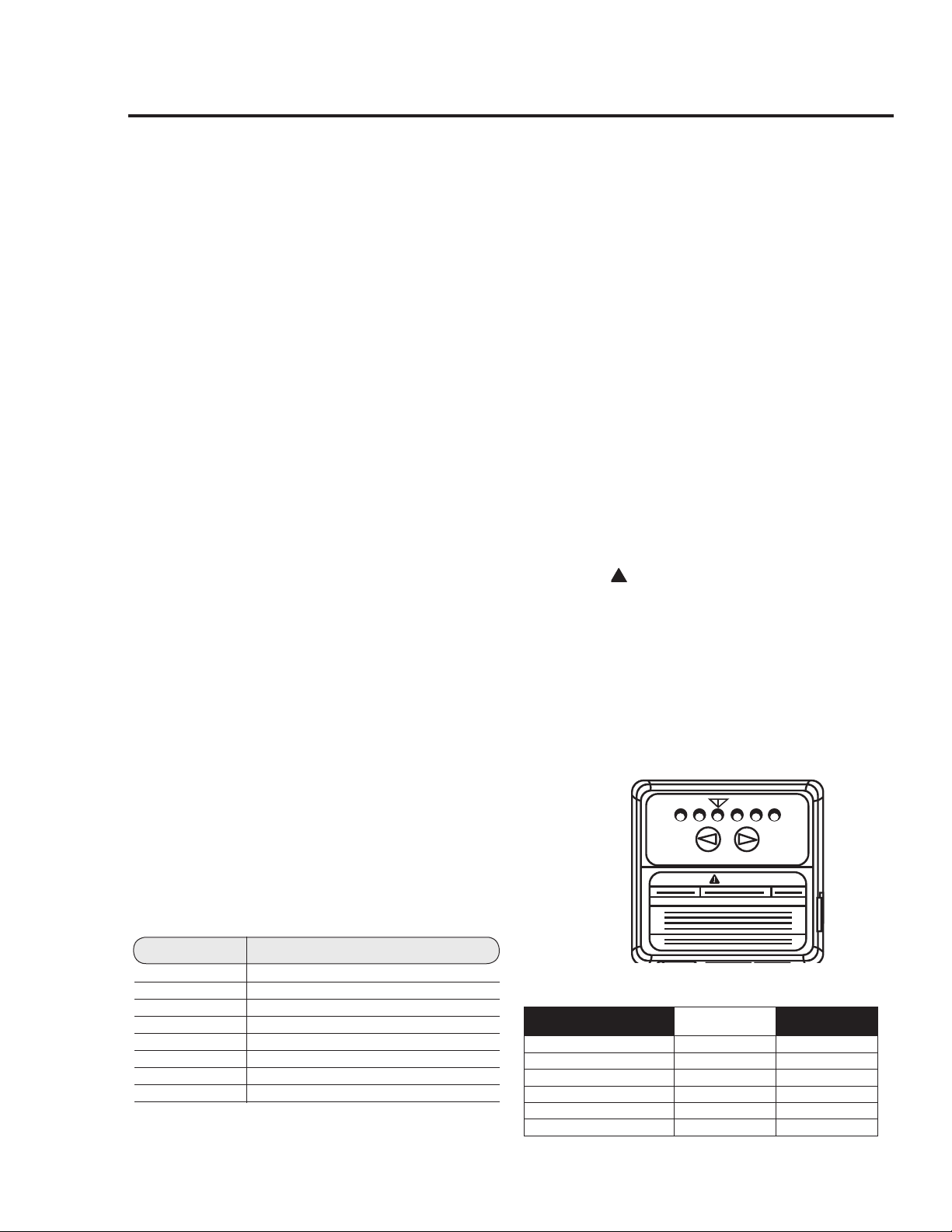
Water Temperature Setting…
Maximum water temperatures occur just
after the burner has shut off. To determine
the water temperature, turn on a hot water
faucet and place a thermometer in the water
stream.
To avoid any unintentional changes in water
temperature settings, the combination gas
control (thermostat) has a tamper resistant
feature for changing the temperature setting.
To change the temperature setting follow
these instructions.
1. "Wake Up" the temperature indicators
by holding down both "COOLER" and
"HOTTER" temperature adjustment
buttons at the same time for one second,
see Figure below. One or two of the
temperature indicators will light up.
These indicators will only remain on
for 30 seconds if no further buttons are
pressed. After 30 seconds the control will
go back to "sleep" mode.
2. Release both of the temperature buttons.
a. To decrease the temperature press and
release the "COOLER" button until
the desired setting is reached.
b. To increase the temperature press and
release the "HOTTER" button until
the desired setting is reached.
NOTICE: Holding down the button
will not continue to lower or raise the
temperature setting. The button must be
pressed and released for each temperature
change desired.
A condition known as “stacking” or
“layering” can occur when a series of short
and frequent hot water draws are taken.
The hottest temperature water will be at the
top of the tank, closest to the outlet pipe
delivering hot water to the home.
Stacking can cause this top layer of water to
be hotter than the water toward the bottom
of the tank near the combination gas control
(thermostat). Therefore, always remember
to test the water temperature with your hand
before use and remember that hotter water
increases the risk of scald injury.
Also, always supervise young children or
others who are incapacitated.
The combination gas control (thermostat)
is constructed with a built in safety shutoff
device designed to shut off the gas supply to
the burner if the main burner is extinguished
for any reason.
The combination gas control (thermostat) is
also equipped with a single use gas shut off
device that will shut off the gas supply to the
burner if the water heater exceeds normal
operating temperatures. Refer to the Before
You Call For Service section of this manual,
or contact your dealer.
!
WARNING: Should overheating occur
or the gas supply fail to shut off, turn off
the manual gas (shutoff) valve to the
appliance.
If the water heater has been subjected to fire,
flood or physical damage, turn off the manu-
al gas (shutoff) valve, and do not operate the
water heater again until is has been checked
by a qualified service technician.
Time/Temperature Relationship in Scalds
Water Temperature Time To Produce a Serious Burn
120°F (49°C) More than 5 minutes
125°F (52°C) 1
1
/2 to 2 minutes
130°F (54°C) About 30 seconds
135°F (57°C) About 10 seconds
140°F (60°C) Less than 5 seconds
145°F (63°C) Less than 3 seconds
150°F (66°C) About 1
1
/2 seconds
155°F (68°C) About 1 second
Table courtesy of Shriners Burn Institute
VACATION
WARNING
VERY
HOT
WARM
A B C
COOLER
HOTTER
Temperature Setting
Display
▼ A B C
Burns on Adult Skin
WARM = approx. 70°F (21°C)
● ○ ○ ○ ○ ○
--------------------
▼ = approx. 120°F (49°C)
○ ○ ● ○ ○ ○
More than 5 minutes
A = approx. 130°F (54°C)
○ ○ ○ ● ○ ○
About 30 seconds
B = approx. 140°F (60°C)
○ ○ ○ ○ ● ○
Less than 5 seconds
C = approx. 150°F (66°C)
○ ○ ○ ○ ○ ●
About 1-1/2 seconds
C-Flashing = approx. 160°F (71°C)
○ ○ ○ ○ ○ ●
About 1/2 seconds
Operating the Water Heater
36

Sequence of Operation
During initial start-up or a call for heat, the con-
trol will verify the vacuum switch is open.
Once the control verifies the vent pressure switch
is open, the control will energize the blower
motor for the pre-purge sequence (approximately
5 seconds).
The control will verify that the vent pressure
switch has closed, ensuring that the blower is
functioning properly and that the venting system
is not blocked.
The control will then proceed through a sequence
of self-diagnostics before initiating a trial for igni-
tion.
During the trial for ignition, the hot surface ignit-
or will warm up.
Once the hot surface ignitor warms up, the main
gas valve will open allowing gas to flow to the
main burner.
Once the main burner ignites, the control will
verify that the burner flame is present through the
flame sense circuit. The hot surface ignitor will
then turn off.
The main burner will remain lit throughout the
heat cycle until the water temperature setting is
reached.
Once the water temperature setting is reached, the
control will close the main gas valve which will
extinguish the main burner flames.
The blower motor will stay energized for an
additional 5 seconds after the control verifies that
the burner flame is extinguished in order to clear
combustion gases from the water heater.
After the post-purge sequence, the control will de-
energize the blower motor and go into a stand-by
mode awaiting the next call for heat.
This water heater is equipped with a flammable
vapor sensor that is monitored continuously by
the electronic control in all modes of operation.
In the event that flammable vapors are detected,
the control will automatically shut down the water
heater and prevent the water heater from being
started again.
The following is a list of materials that will cause
the Flammable Vapor Sensor to shut down the
water heater.
Vapors of Gasoline.
Vapors of certain flammable paints, stains, and
thinners.
Vapors of vent pipe Cement & Solvents.
Bleach (direct contact with flammable vapor
sensor).
Some other flammable materials and their
vapors.
If the flammable vapor sensor shuts down the
water heater, then the electronic control will dis-
play the appropriate error code and you should
then promptly contact a qualified service techni-
cian.
Refer to the “NOTICE” on page 3 for additional
information.
37
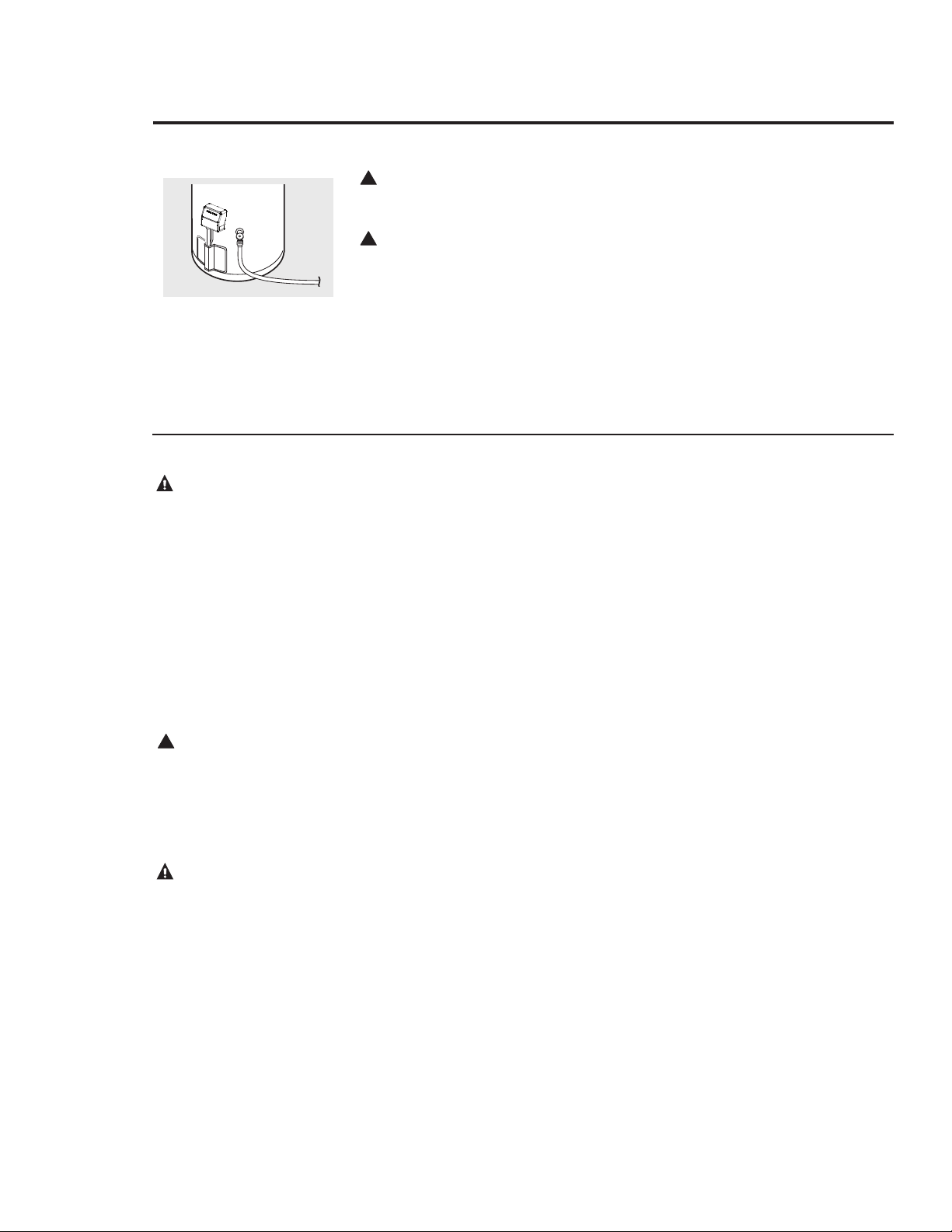
Care and Cleaning of the Water Heater
Draining the Water Heater
!
CAUTION: Shut off gas to the
water heater at the manual gas shut-
off valve before draining water.
!
DANGER: Before manually
operating the temperature and
pressure relief valve, make certain no
one will be exposed to the hot water
released by the valve. The water
drained from the tank may be hot
enough to present a scald hazard and
should be directed to a suitable drain
to prevent injury or damage.
Before turning off the cold water
supply to the water heater, open a hot
water faucet allowing sufficient cold
water into the tank to prevent the
risk of a scald injury while draining
the water heater. Once the water in
the tank is no longer hot, turn off the
cold water supply to the water heater.
Open a hot water faucet or lift the
handle on the relief valve to admit air
to the tank.
Attach a garden hose to the drain valve
on the water heater and direct the stream
of water to a drain. Open the valve.
Routine Preventative Maintenance
Properly maintained, your water heater
will provide years of dependable trouble-
free service.
It is recommended that a periodic inspec-
tion of the combination gas control
(thermostat), burner, relief valve, internal
flue-way, vent and combustion air-inlet
systems be made by service personnel
qualified in gas appliance repair.
It is suggested that a routine preventative
maintenance program be established and
followed by the user.
Inspect the combustion air-inlet and vent
systems. Make certain that all joints are
secure and that combustion air-inlet and
vent pipe supports are all in place. Check
the outdoor combustion air-inlet and
vent terminals to see that they are free of
obstructions, and that there is no damage
nearby caused by condensate.
Periodically, lift and release the lever
handle on the temperature pressure relief
valve, located near the top of the water
heater, to make certain the valve oper-
ates freely. Allow several gallons to flush
through the discharge line to an open
drain.
NOTICE: If the temperature and pres-
sure relief valve on the water heater
discharges periodically, this may be
due to thermal expansion in a closed
water system. Contact the water sup-
plier or your plumbing contractor on
how to correct this.
DO NOT plug the relief valve outlet.
A water heater’s tank can act as a settling
basin for solids suspended in the water. It
is therefore not uncommon for hard water
deposits to accumulate in the bottom of
the tank. If allowed to accumulate, these
solids can cover the combination gas
control (thermostat) sensors, causing the
sensors to operate erratically. Because
accumulated solids can prevent the com-
bination gas control (thermostat) sensors
from accurately reading the water tem-
perature, the water at the fixture can be
hotter than the combination gas control
(thermostat) setting. It is suggested that
a few quarts of water be drained from the
water heater’s tank every month to clean
the tank of these deposits.
Rapid closing of faucets or solenoid
valves in automatic water using appli-
ances can cause a banging noise heard in
a water pipe. Strategically located risers
in the water pipe system or water hammer
arresting devices can be used to minimize
the problem.
The anode rod should be removed from
the water heater’s tank periodically, for
inspection and replaced when more than
6 in. (15.2 cm) of core wire is exposed at
either end of the rod.
Make sure the cold water supply is turned
off before removing anode rod.
This water heater incorporates a combus-
tion shut off device that shuts the opera-
tion of the water heater down if undesir-
able combustion conditions occur, such
as the presence of flammable vapors or
blockage of the combustion air-inlet and/
or vent systems. Please contact a quali-
fied service technician if this occurs.
DANGER: Before
manually operating the
relief valve, make certain
no one will be exposed to
the danger of the hot
water released by the
valve. The water may be
hot enough to create a
scald hazard. The water
should be released into a
suitable drain to prevent
injury or property damage.
DANGER: Failure to
perform the recommended
Routine Preventative
Maintenance can harm the
proper operation of this
water heater, which can
cause carbon monoxide
dangers, excessive hot
water temperatures and
other potentially
hazardous conditions.
!
DANGER: Hotter
water increases the
potential for Hot Water
Scalds.
38
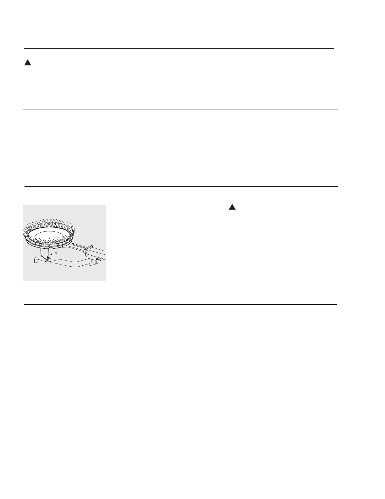
Housekeeping
Make sure the Flammable Vapor Sensor is
not blocked or obstructed.
DO NOT expose the Flammable Vapor
Sensor to water, solvents or cleaning
agents.
!
DANGER: Combustible
materials, such as clothing,
cleaning materials, or
flammable liquids, etc., must
not be placed against or next
to the water heater.
Burner Inspection
Visually inspect the hot surface ignitor and
main burner periodically.
Through the sight glass, inspect the hot
surface ignitor with the main burner off
and inspect the main burner while firing.
If any unusual burner operation is noted,
the water heater should be shut off
until qualified service assistance can be
obtained.
!
CAUTION: For your safety, cleaning
of the burner must be performed only
by qualified service personnel, as it
involves the disconnection of gas piping
and leak testing. The burner chamber is
a sealed area. If the burner access door
is removed, the burner access door
gasket must be replaced.
For cleaning, remove the burner from the
water heater. A vacuum cleaner can be
used on the burner and floor shield inside
the water heater. The burner can also be
cleaned by scrubbing with mild detergent.
Representative burner flame
pattern
Combustion Air-Inlet and Vent System Inspection
Inspect the combustion air-inlet and vent
systems. Make certain that all joints are
secure and that combustion air-inlet and
vent system supports are all in place. Check
the outdoor combustion air-inlet and vent
system terminals to see that they are free of
obstructions, and that there is no damage
nearby caused by condensate.
Vacation and Extended Shut-Down
If the water heater is to remain idle for an
extended period of time, the power and
water to the appliance should be turned off
to conserve energy and prevent a build-up
of dangerous hydrogen gas.
The water heater and piping should be
drained if they might be subjected to freez-
ing temperatures.
After a long shut-down period, the water
heater’s operation and controls should
be checked by qualified service person-
nel. Make certain the water heater is
completely filled again before placing it in
operation.
NOTICE: Refer to the
Hydrogen Gas Caution in
the Operating Instructions.
Anode Rod
This water heater is equipped with an
anode rod designed to prolong the life of
the glass lined tank. The anode rod is slow-
ly consumed, thereby eliminating or mini-
mizing corrosion of the glass lined tank.
Water sometimes contains a high sulfate
and/or mineral content and together with
cathodic protection process can produce
a hydrogen sulfide, or rotten egg odor in
the heated water. Chlorination of the water
supply should minimize the problem.
NOTICE: Do not remove
the anode rod from the
water heater’s tank, except
for inspection and/or
replacement, as operation
with the anode rod removed
will greatly shorten the
life of the glass lined tank
and will exclude warranty
coverage.
39
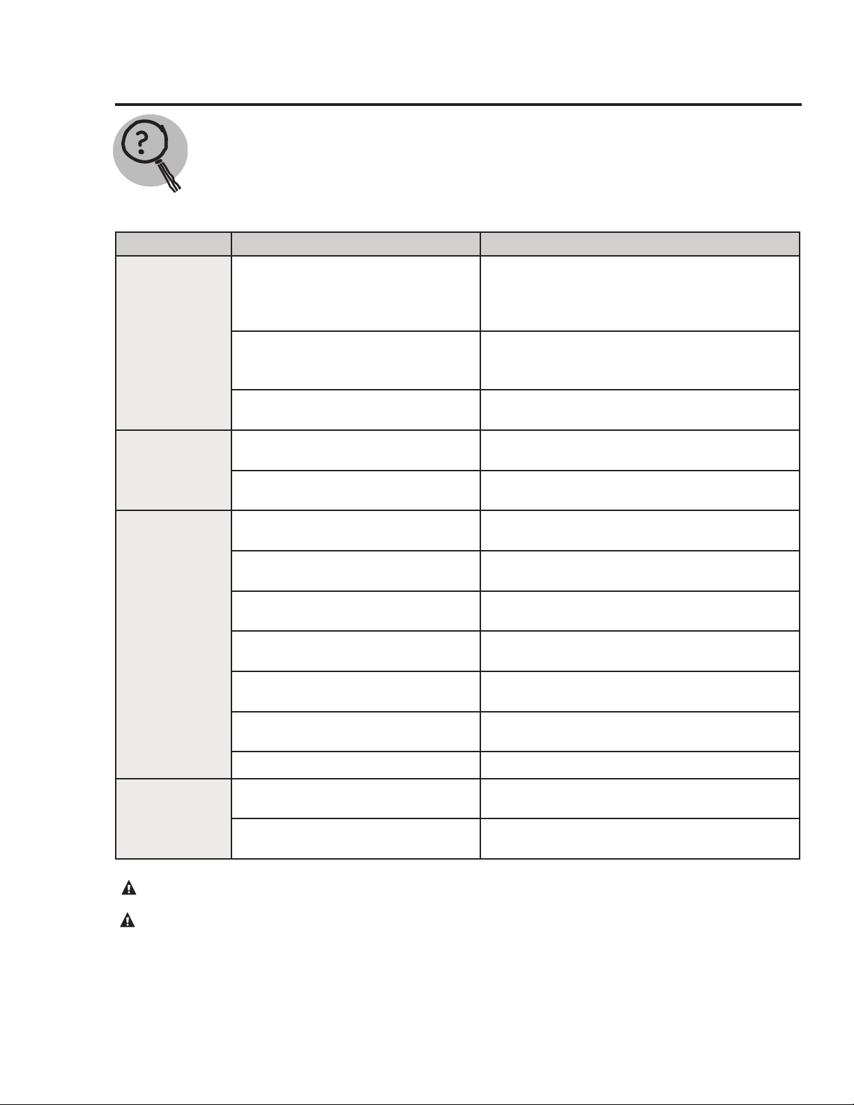
Before You Call for Service
Troubleshooting Tips
Save time and money! Review the charts on the following pages first and you may not need to call
for service.
This water heater incorporates shut off devices that shuts the operation of the water heater down if
undesirable combustion conditions occur, such as the presence of flammable vapors or blockage of the vent
and/or combustion air-inlet systems. Please contact a Qualified Service Technician if this occurs.
Problem Possible Causes What To Do
Condensation This usually happens when a new
heater is filled for the first time.
This is normal, after the water in the tank warms
up, the condensation will disappear. Refer to
page 10 for more information.
Moisture from the products of com-
bustion condensing on the tank sur-
face.
This is normal and will disappear in time. Refer
to page 10 for more information.
An undersized water heater will cause
condensation.
Use a water heater size that meets the require-
ments of your needs.
Yellow flame or
soot
Scale on top of the burner. Contact a qualified service technician to remove
scale.
Vent and/or combustion air-inlet sys-
tems are blocked.
Remove obstruction or debris from vent and/or
combustion air-inlet systems.
Unable to light
the main burner
Air in gas line. Contact a qualified service technician to purge
the air from the gas line.
Blocked vent system. Contact a qualified service technician to evaluate
vent system for blockage.
Blocked combustion air-inlet system. Contact a qualied service technician to evaluate
the combustion air-inlet system for blockage.
Pressure switches. Make sure the pressure switch hoses are not
"kinked".
Wire connection(s) not fully secured. Contact a qualified service technician to confirm
wire connections.
Combustion shutoff device tripped. Combustion Shutoff Device(s) should be inspect-
ed by a qualified service technician.
Gas control problem. Contact a qualified service technician.
Main burner does
not stay lit
Energy shutoff device open. The combination gas control (thermostat) should
be replaced by a qualified service technician.
Combustion shutoff device
tripped.
The combustion shutoff device should be inspect-
ed by a qualified service technician.
CAUTION: For your safety DO NOT attempt repair of gas piping, combination gas control (thermostat), burners, vent and/
or combustion air-inlet systems or other safety devices. Refer repairs to qualified service personnel.
CAUTION: Label all wires prior to disconnection when servicing controls. Wiring errors can cause improper and
dangerous operation. VERIFY PROPER OPERATION AFTER SERVICING.
40
Before You Call For Service
Troubleshooting Tips
Save time and money! Review the charts on the following pages first and you may not need to call
for service.
This water heater incorporates shut off devices that shut the operation of the water heater down if
undesirable combustion conditions occur, such as the presence of flammable vapors or blockage of the
vent and /or combustion air-inlet systems. Please contact a Qualified Service Technician if this occurs.
CAUTION: Label all wires prior to disconnection when servicing controls. Wiring errors can cause improper and
dangerous operation. VERIFY PROPER OPERATION AFTER SERVICING.
Problem Possible Causes What to Do
Rumbling noise
Scale and sediment. Drain the water heater to remove scale and
sediment from the tank. Refer to page 38.
Relief valve pro-
ducing popping
noise or draining
Pressure build up caused by thermal
expansion in a closed system.
This is an unacceptable condition and must
be corrected. Contact the water supplier or
plumbing contractor on how to correct this.
Do not plug the relief valve outlet.
Not enough or no
hot water
Water usage may have exceeded the
capacity of the water heater.
Wait for the water heater to recover after an
abnormal demand.
Low gas pressure. Check gas supply pressure and manifold
pressure.
The combination gas control
(thermostat) may be set too low.
See the "Water Temperature Setting"of the
water heater section of this manual.
Leaking or open hot water faucets. Make sure all faucets are closed.
Check valve error codes. Refer to gas valve error code table on page 42.
"ON / OFF" switch turned off. Turn "ON".
Blower unplugged. Plug in. verify power supply (120 VAC).
Combustion Shutoff Device tripped. Contact a qualied service technician.
Water is too hot
The combination gas control
(thermostat) is set too high.
See the "Water Temperature Setting"of the
water heater section of this manual.
Combination gas control (thermostat)
is defective.
Contact a qualied service technician
to replace the combination gas control
(thermostat).
CAUTION: For your safety DO NOT attempt repair of gas piping, combination gas control (thermostat), burners, vent
and or combustion air-inlet systems or other safety devices. Refer repairs to qualified service personnel.
41
Gas Valve LED Codes
CAUTION: Label all wires prior to disconnection when servicing controls. Wiring errors can cause improper and
dangerous operation. VERIFY PROPER OPERATION AFTER SERVICING.
CAUTION: For your safety DO NOT attempt repair of gas piping, combination gas control thermostat, burners, vent
and/or combustion air-inlet systems or other safety devices. Refer repairs to qualified service personnel.
LED Status Problem Solution
○ ○
▼ A B C
● ○ ○ ● ○ ○
An open earth ground circuit to the
ignition system.
1. Check that the earth ground connection is properly
connected.
2. Check that the ground conductor on the water heater
is properly connected.
○ ○ ▼ A B C
● ○ ● ○ ● ○
Wiring error or a high resistance to
earth ground.
1. Check proper connection of line neutral and hot
wires.
2. Check that the water heater is securely connected to
earth ground.
○ ○ ▼ A B C
● ○ ● ○ ○ ○
Pressure switch remained closed lon-
ger than 5 seconds after the call for
heat began.
1. Verify that the wiring to the pressure switch(es) is
correct.
2. Replace the pressure switch(es).
○ ○ ▼ A B C
● ○ ● ○ ○ ●
Pressure switch remained opened lon-
ger than 5 seconds after the combus-
tion blower was energized.
1. Verify that the wiring to the pressure switch(es) is
correct.
2. Verify that the wiring to the pressure switch(es) is
connected correctly.
3. Check the vent and / or combustion air-inlet systems
for obstructions.
○ ○ ▼ A B C
● ○ ● ○ ● ●
Error in the hot surface ignitor circuit. 1. Check that all wiring is correct and secure.
2. Replace hot surface ignitor.
○ ○ ▼ A B C
● ○ ○ ● ● ○
System in lockout.
1. Gas supply is off or too low to operate. Turn on the
gas supply and / or increase the inlet gas supply pres-
sure.
2. Hot surface ignitor not positioned correctly.
3. Low voltage to the water heater. Increase supply volt-
age to rated voltage.
4. Electric polarity to unit is incorrect - test and correct.
5. Check the vent and /or combustion air-inlet systems
for obstructions.
○ ○ ▼ A B C
● ○ ○ ○ ● ●
Problem in the combination gas valve
driver circuit.
1. Turn power to the water heater off for 10 seconds and
then back on.
2. Replace the combination gas control (thermostat).
○ ○ ▼ A B C
● ○ ● ● ● ○
Problem with the internal circuit. 1. Turn power to the water heater off for 10 seconds and
then back on.
2. Replace the combination gas control (thermostat).
○ ○ ▼ A B C
● ● ● ● ● ●
Problem with the internal circuit. 1. Turn power to the water heater off for 10 seconds and
then back on.
2. Replace the combination gas control (thermostat).
○ ○ ▼ A B C
● ○ ○ ○ ● ○
Flame signal sensed out of
proper sequence.
1. Replace the combination gas control. (thermostat)
○ ○ ▼ A B C
● ○ ○ ● ● ●
ECO activated. 1. Replace the combination gas control (thermostat).
○ ○ ▼ A B C
● ○ ● ● ○ ○
One of the temperature adjust
buttons stuck closed.
1. Press and release each of the buttons once.
2. Replace the combination gas control (thermostat).
○ ○ ▼ A B C
● ○ ● ● ○ ●
Water temperature sensor is either
open or short circuited.
1. Check that all wiring is correct and secure.
2. Replace the combination gas control (thermostat).
○ ○ ▼ A B C
● ○ ○ ● ○ ●
Unit shuts down. 1. Check for correct wiring to FV sensor.
2. Check for open circuits to FV sensor.
3. Replace FV sensor.
○ ○ ▼ A B C
● ○ ○ ○ ○ ●
Unit shuts down and in lockout.
1. FV sensor detected presence of ammable vapors.
2. Contact a service agency.
42
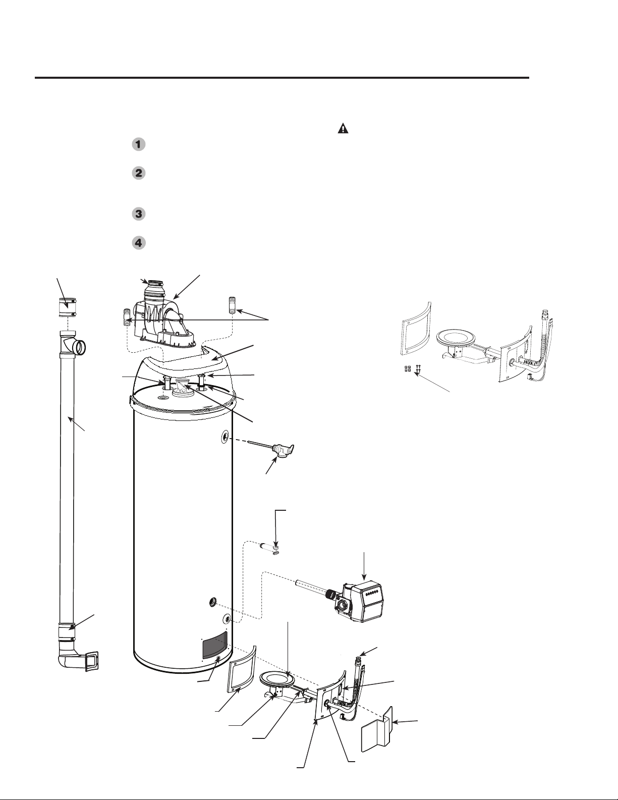
Replacement Parts
For 40, 50, 65, and 75 Gallon Models equipped for use with Natural or Liquified Petroleum/LP gas.
Instructions For Placing a Parts Order
All parts orders should include:
The model and serial number of the water
heater from the rating plate.
Specify type of gas (Natural or Liquified
Petroleum/LP gas) as marked on the rat-
ing plate.
Part description (as noted below) and
number of parts desired.
Refer to page 44.
CAUTION: For your safety, DO NOT
attempt repair of gas piping, gas control
(thermostat), burners, vent connectors or
other safety devices. Refer repairs to
qualified service personnel.
Use only original equipment replacement
parts.
43
Blower
Assembly
Flue Baffle
Anode Rod
** Heat Trap Nipples
Dip Tube
Dip Tube Gasket
Drain Valve
Temperature and Pressure
Relief Valve
Combination
Gas Control (Thermostat)
*Igniter
*Burner Supply Tube
*Burner
Jacket Door
*Burner Access Door Grommet
*Sight Glass
*Burner Access Door
*Burner Access Door Gasket
*Burner Orifice
Flammable Vapor Sensor
** Rubber
Coupling
Combustion
Air-Inlet
Assembly
(not a
replacment
part
Top Cap
(certain models only)
*Burner Assembly Kit
The kit provides extra speed clips and
tamper resistant screws.
** May differ in actual appearance.
○ ○ ▼ A B C
● ○ ○ ● ○ ○
○ ○ ▼ A B C
● ○ ● ○ ● ○
○ ○ ▼ A B C
● ○ ● ○ ○ ○
○ ○ ▼ A B C
● ○ ● ○ ○ ●
○ ○ ▼ A B C
● ○ ● ○ ● ●
○ ○ ▼ A B C
● ○ ○ ● ● ○
○ ○ ▼ A B C
● ○ ○ ○ ● ●
○ ○ ▼ A B C
● ○ ● ● ● ○
○ ○ ▼ A B C
● ● ● ● ● ●
○ ○ ▼ A B C
● ○ ○ ○ ● ○
○ ○ ▼ A B C
● ○ ○ ● ● ●
○ ○ ▼ A B C
● ○ ● ● ○ ○
○ ○ ▼ A B C
● ○ ● ● ○ ●
○ ○ ▼ A B C
● ○ ○ ● ○ ●
○ ○ ▼ A B C
● ○ ○ ○ ○ ●
1. FV sensor detected presence of ammable vapors.
Combustion
Air-Inlet
Coupling
Combustion
Air-Inlet
Coupling

44
The Commonwealth of Massachusetts requires compliance with regula-
tion
5.08: Modications to NFPA-54, Chapter 10 : 248 CMR 4.00
and 5.00 for installation of through – the – wall vented gas appliances as
follows:
(1) Revise NFPA-54 section 10.5.4.2 by adding a second exception as fol-
lows:
Existing chimneys shall be permitted to have their use continued when a gas
conversion burner is installed, and shall be equipped with a manually reset
device that will automatically shut off the gas to the burner in the event of a
sustained back-draft.
(2) Revise 10.8.3 by adding the following additional requirements:
(a) For all side wall horizontally vented gas fueled equipment installed in
every dwelling, building or structure used in whole or in part for residential
purposes, including those owned or operated by the Commonwealth and
where the side wall exhaust vent termination is less than seven (7) feet above
nished grade in the area of the venting, including but not limited to decks
and porches, the following requirements shall be satised:
1. INSTALLATION OF CARBON MONOXIDE DETECTORS. At the time
of installation of the side wall horizontal vented gas fueled equipment, the
installing plumber or gastter shall observe that a hard wired carbon monox-
ide detector with an alarm and battery back-up is installed on the oor level
where the gas equipment is to be installed. In addition, the installing plumber
or gastter shall observe that a battery operated or hard wired carbon mon-
oxide detector with an alarm is installed on each additional level of the dwell-
ing, building or structure served by the side wall horizontal vented gas fueled
equipment. It shall be the responsibility of the property owner to secure the
services of qualied licensed professionals for the installation of hard wired
carbon monoxide detectors
a. In the event that the side wall horizontally vented gas fueled equipment is
installed in a crawl space or an attic, the hard wired carbon monoxide detec-
tor with alarm and battery back-up may be installed on the next adjacent oor
level.
b. In the event that the requirements of this subdivision can not be met at the
time of completion of installation, the owner shall have a period of thirty (30)
days to comply with the above requirements; provided, however, that during
said thirty (30) day period, a battery operated carbon monoxide detector with
an alarm shall be installed.
2. APPROVED CARBON MONOXIDE DETECTORS. Each carbon
monoxide detector as required in accordance with the above provisions shall
comply with NFPA 720 and be ANSI/UL 2034 listed and IAS certied.
3. SIGNAGE. A metal or plastic identication plate shall be permanently
mounted to the exterior of the building at a minimum height of eight (8) feet
above grade directly in line with the exhaust vent terminal for the horizon-
tally vented gas fueled heating appliance or equipment. The sign shall read,
in print size no less than one-half (1/2) inch in size, "GAS VENT DIRECTLY
BELOW. KEEP CLEAR OF ALL OBSTRUCTIONS".
4. INSPECTION. The state or local gas inspector of the side wall horizon-
tally vented gas fueled equipment shall not approve the installation unless,
upon inspection, the inspector observes carbon monoxide detectors and
signage installed in accordance with the provisions of 248 CMR 5.08(2)(a)1
through 4.
(b) EXEMPTIONS: The following equipment is exempt from 248 CMR
5.08(2)(a)1 through 4:
1. The equipment listed in Chapter 10 entitled "Equipment Not Required To
Be Vented" in the most current edition of NFPA 54 as adopted by the Board;
and
2. Product Approved side wall horizontally vented gas fueled equipment in-
stalled in a room or structure separate from the dwelling, building or structure
used in whole or in part for residential purposes.
(c) MANUFACTURER REQUIREMENTS - GAS EQUIPMENT VENTING
SYSTEM PROVIDED. When the manufacturer of Product Approved side
wall horizontally vented gas equipment provides a venting system design or
venting system components with the equipment, the instructions provided
by the manufacturer for installation of the equipment and the venting system
shall include:
1. Detailed instructions for the installation of the venting system design or
the venting system components; and
2. A complete parts list for the venting system design or venting system.
(d) MANUFACTURER REQUIREMENTS - GAS EQUIPMENT VENTING
SYSTEM NOT PROVIDED. When the manufacturer of a Product Approved
side wall horizontally vented gas fueled equipment does not provide the parts
for venting the ue gases, but identies "special venting systems", the fol-
lowing requirements shall be satised by the manufacturer:
1. The referenced "special venting system" instructions shall be included with
the appliance or equipment installation instructions; and
2. The "special venting systems" shall be Product Approved by the Board,
and the instructions for that system shall include a parts list and detailed
installation instructions.
(e) A copy of all installation instructions for all Product Approved side wall
horizontally vented gas fueled equipment, all venting instructions, all parts
lists for venting instructions, and/or all venting design instructions shall
remain with the appliance or equipment at the completion of the installation.
IF YOU NEED SERVICE
1. Should you have any questions about your new water heater, or if it requires adjustment, repair, or rou-
tine maintenance, it is suggested that you first contact your installer, plumbing contractor or previously
agreed upon service agency. In the event the firm has moved, or is unavailable, refer to the telephone
directory, commercial listings or local utility for qualified service assistance.
2. Should your problem not be solved to your complete satisfaction, you should then contact the
Manufacturer’s National Service Department at the following address:
1241 Carwood Court
Montgomery, Alabama 36117
Phone: 1-800-432-8373
When contacting the manufacturer, the following information will be requested:
a. Model and serial number of the water heater as shown on the rating plate attached to the jacket of the
heater.
b. Address where the water heater is located and physical location.
c. Name and address of installer and any service agency who performed service on the water heater.
d. Date of original installation and dates any service work was performed.
e. Details of the problems as you can best describe them.
f. List of people, with dates, who have been contacted regarding your problem.
Important Instructions for the Commonwealth of Massachusetts