Loading ...
Loading ...
Loading ...
23
-B-
-A-
-B-
d
.008
d
.010
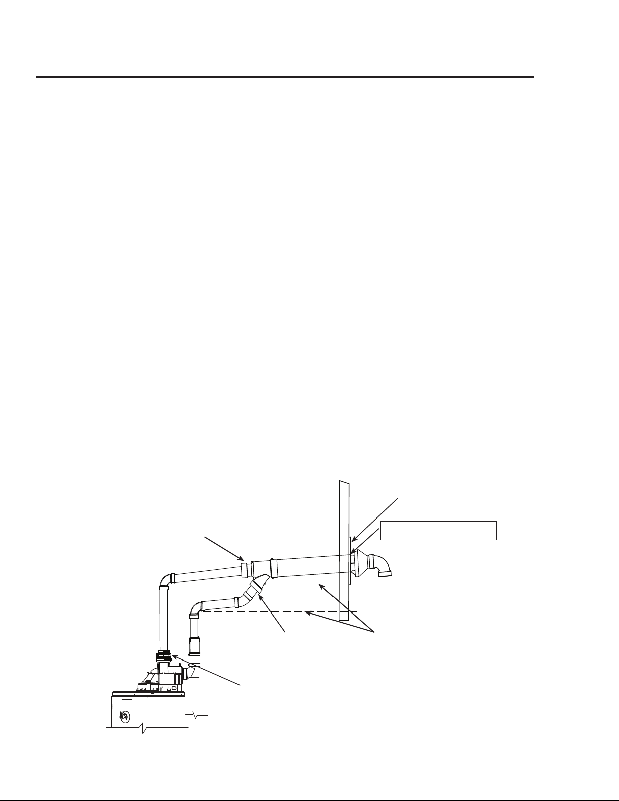
Horizontal Vent - Concentric Terminal Installation
Rear of Rain Cap Flush
with Outside of Wall
Outside of
Building
Inside of
Building
Raise horizontal pipe upwards 1/8 in. per
foot (10 mm per m) min.
Combustion Air-Inlet
System
3 in. (7.6 cm)
Vent
System
3 in. (7.6 cm)
Optional - Condensate
Management Drain
Port*
*See Condensate Management Section for
additional information about optional piping.
• Measure and cut the straight inner vent
pipe of the concentric terminal assembly
so it is 13 in. (5.1 cm) longer in length
than the outer, straight combustion air-inlet
pipe.
• Ensure that there is no insulation or debris
in the pipe.
Assemble the vent pipe assembly.
• Clean and cement the rain cap to the inner,
straight vent pipe.
• From the outside, slide the vent pipe with
rain cap assembly through the combustion
air-inlet pipe until the rear of the rain cap
is ush with the outside wall.
• Clean and cement the rain cap to the com-
bustion air-inlet pipe.
• Clean and cement a 3 in. (7.6 cm) diam-
eter, SDR 35, PVC, 90°, 1/4 standard bend
elbow to the rain cap. See below.
From the inside, clean and cement the Wye t-
ting to the vent and combustion air-inlet pipes
of the termination assembly.
Complete the installation of the remainder
of the vent system and attach it to the vent
connector tting on the water heater’s blower
assembly.
IMPORTANT: Raise all horizontal sections
upwards a minimum of 1/8 in. per foot
(10 mm per m). See below.
DO NOT use unequal diameters of pipe and
ttings for the vent and combustion air-inlet
systems except as dened previously
NOTICE: The difference between the vent
and combustion air-inlet system equivalent
lengths must be no greater than 5 ft.
(1.5 m).
Complete the installation of the remainder of
the combustion air-inlet system and attach it
to the combustion air-inlet connector tting
on the water heater’s combustion air-inlet tube
assembly.
Support vertical and horizontal lengths of the
vent and combustion air-inlet systems as previ-
ously mentioned.
IMPORTANT: Ensure that all the coupling
clamps are tight before allowing the water
heater to operate.
2 ft. x 2 ft. (60 cm x 60 cm)
Sheet Metal Shield on Brick
or Masonry Walls
Loading ...
Loading ...
Loading ...