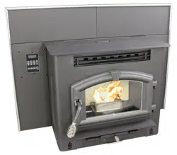
* All Pictures In This Manual Are For Illustrative Purposes Only. Actual Product May Vary.
© 2020 United States Stove Company, 227 Industrial Park Rd., South Pittsburg, TN 37380 Ph. 800-750-2723
THIS MANUAL IS SUBJECT TO CHANGE WITHOUT NOTICE.
Owner’s Instruction and Operation Manual
U.S. Environmental Protection Agency
Certified to comply with 2020 particulate
emissions standards.
SAFETY NOTICE: If this heater is not properly installed, a house fire may result. For
your safety, follow the installation instructions. Never use make-shift compromises
during the installation of this heater. Contact local building or fire ocials about
permits, restrictions and installation requirements in your area. NEVER OPERATE
THIS PRODUCT WHILE UNATTENDED.
CAUTION! Please read this entire manual before you install or use your new room
heater. Failure to follow instructions may result in property damage, bodily injury, or
even death. Improper Installation Will Void Your Warranty!
Save These Instructions In A Safe Place For Future Reference.
CALIFORNIA PROPOSITION 65 WARNING:
This product can expose you to chemicals including carbon
monoxide, which is known to the State of California to cause
cancer, birth defects, and/or other reproductive harm. For
more information, go to www.P65warnings.ca.gov
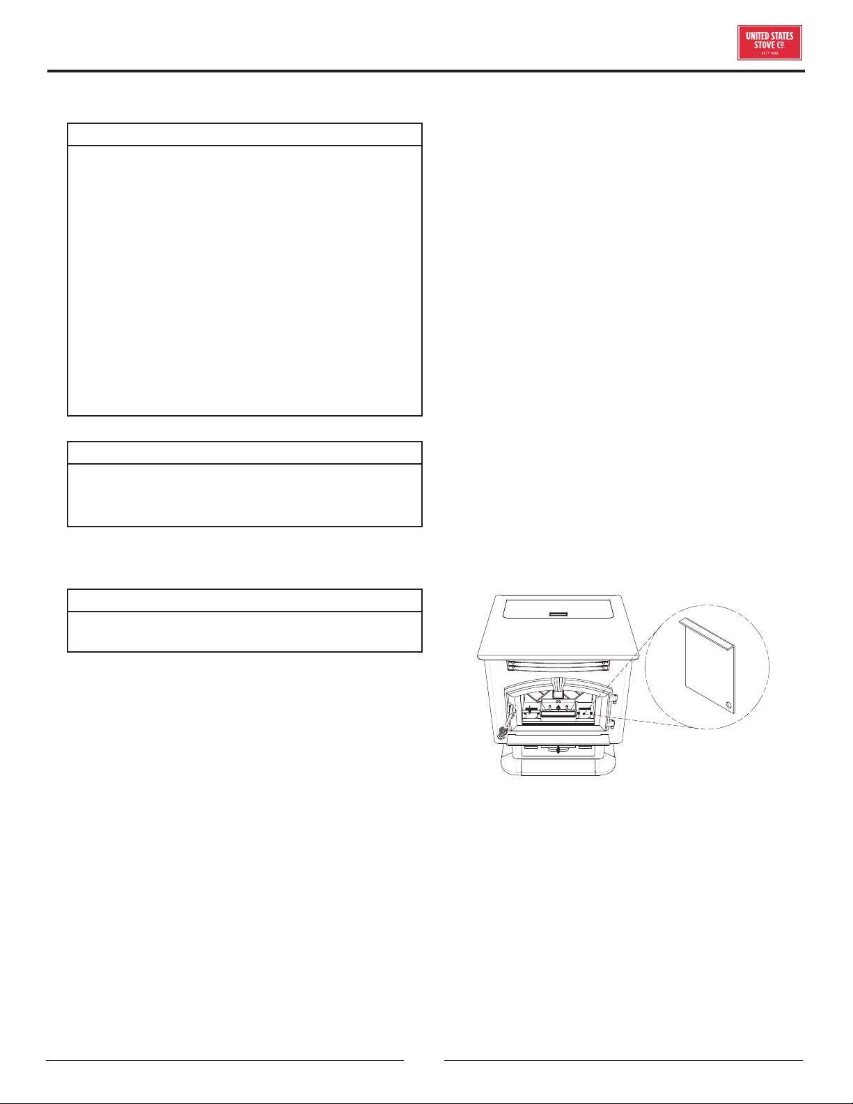
851772K-0402K
6041i
R
Report Number: F20-573
Tested Per EPA Method ASTM E2779-10
and ASTM E1509-12 (2017)
Model Number:
2
© 2021 United States Stove Company
SPECIFICATIONS
This manual describes the installation and operation of the USSC 6041I wood heater. This heater meets the 2020 U.S.
Environmental Protection Agency’s crib wood emission limits for wood heaters sold after May 15, 2020. Under specific
test conditions this heater has been shown to deliver heat at rates ranging from 7,540 to 21,811 Btu/hr output. This
heater achieved a particulate emissions rate of 1.3 g/hr and 58% eciency when tested to method ASTM E 2779-10.
WARNING:
IT IS AGAINST FEDERAL REGULATIONS TO OPERATE THIS WOOD HEATER IN A MANNER INCONSISTENT
WITH THE OPERATING INSTRUCTIONS IN THE OWNER’S MANUAL.
For Customer Service, please call:
1-800-750-2723 Ext 5050 or;
Text to 423-301-5624 or;
Email us at:
customerservice@usstove.com
Note: Register your product online at
www.usstove.com or download the free
app today. This app is available only
on the App Store for iPhone and iPad.
Search US Stove. Save your receipt with
your records for any claims.
Heating Specifications
Heating Capacity 1,000-2,000 Sq. Ft
* Pellet size may eect the actual rate of fuel feed
and burn times. Fuel feed rates may vary by as much
as 20%. Use PFI listed fuel for best results.
Fuel Storage Capacity 60 Lbs.
Flue Size 3” or 4”
Electrical Specifications
Electrical Rating 120 Volts, 60 HZ, 15 Amps
Dimensions
Overall: Height x Width X Depth 29” X 24” X 28” (737 mm X 610 mm X 711 mm)
© 2021 United States Stove Company
3
INSTALLATION CHECKLIST
Your Wood Stove should be installed by a qualified installer only. An NFI qualified Installer can be found at www.
nficertified.org/public/find-an-nfi-pro/
CUSTOMER SERVICE
1-800-750-2723 ext 5050
Text to 423-301-5624
Email to: Customerservice@usstove.com
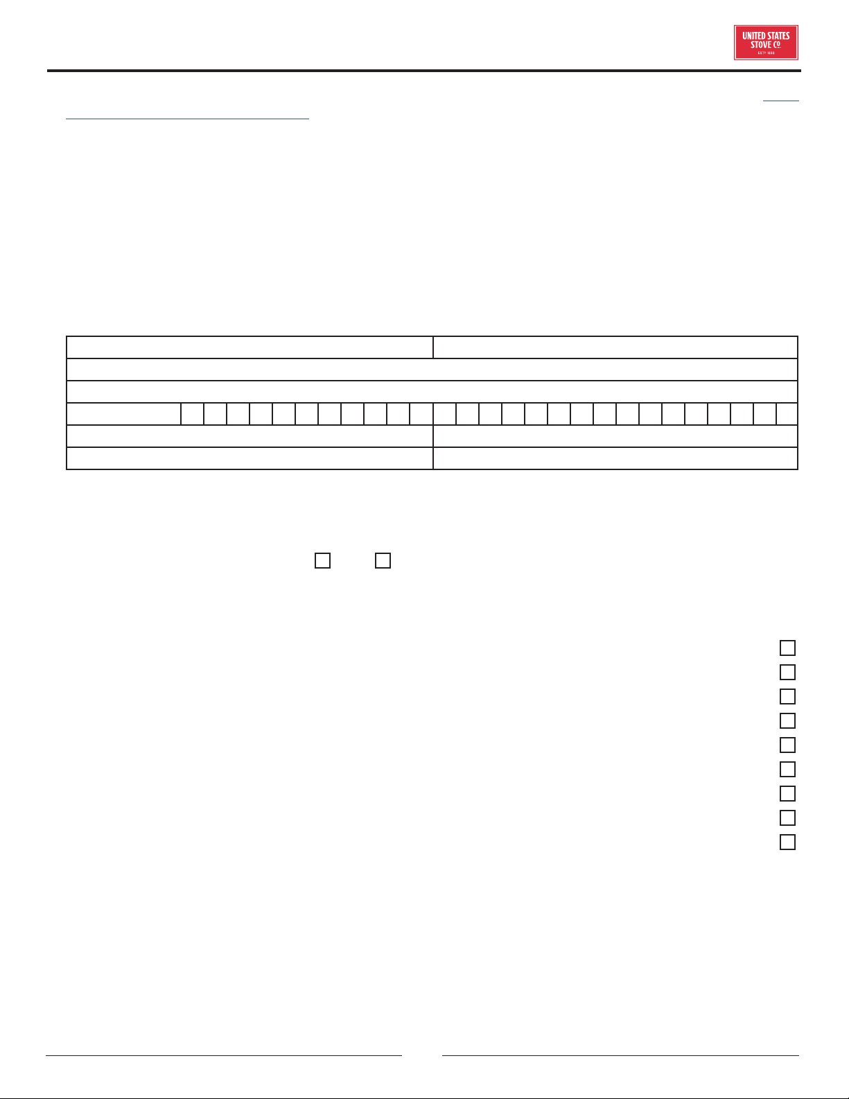
COMMISSIONING CHECKLIST
This checklist is to be completed in full by the qualified person who installs this unit. Keep this page for future reference.
Failure to install and commission according to the manufacturer’s instructions and complete this checklist will
invalidate the warranty.
Please Print
Customer Name: Telephone Number:
Address:
Model:
Serial Number:
Installation Company Name: Phone Number:
Installation Technician’s Name: License Number:
DESCRIPTION OF WORK
Location of installed appliance: __________________________________________________________________________________
Venting System: New Venting System Yes No If yes, Brand ____________________________________________
If no, Date of inspection of existing venting system: _______________________________________________________________
COMMISSIONING
Confirm Hearth Pad Installation as per Installation Instructions ...................................................................................................
Confirm proper placement of internal parts ..........................................................................................................................................
Check soundness of door gasket and door seals .................................................................................................................................
Confirm clearances to combustibles as per installation instructions in this manual ..............................................................
Check the operations of the air controls .................................................................................................................................................
Confirm the venting system is secure and sealed ...............................................................................................................................
Confirm the stove starts and operates properly ..................................................................................................................................
Check to ensure a CO alarm is installed as per local building codes and is functional ............................................................
Explain the safe operation, proper fuel usage, cleaning, and routine maintenance requirements .......................................
Declaration of Completion: As the qualified person responsible for the work described above, I confirm that the appliance
as associated work has been installed as per manufacturer’s instructions and following any applicable building and
installation codes.
Signed: ______________________________________ Print Name: __________________________________Date: ______________
Home Owner: RETAIN THIS INFORMATION FOR FUTURE REFERENCE
4
© 2021 United States Stove Company
SPECIFICATIONS
CAUTION:
DISCONNECT THE POWER CORD BEFORE
SERVICING THIS HEATER
For the following assemblies, we suggest locating the
unit near it’s desired location. Depending on installation,
you may want to connect the exhaust venting before
installing the facade parts.
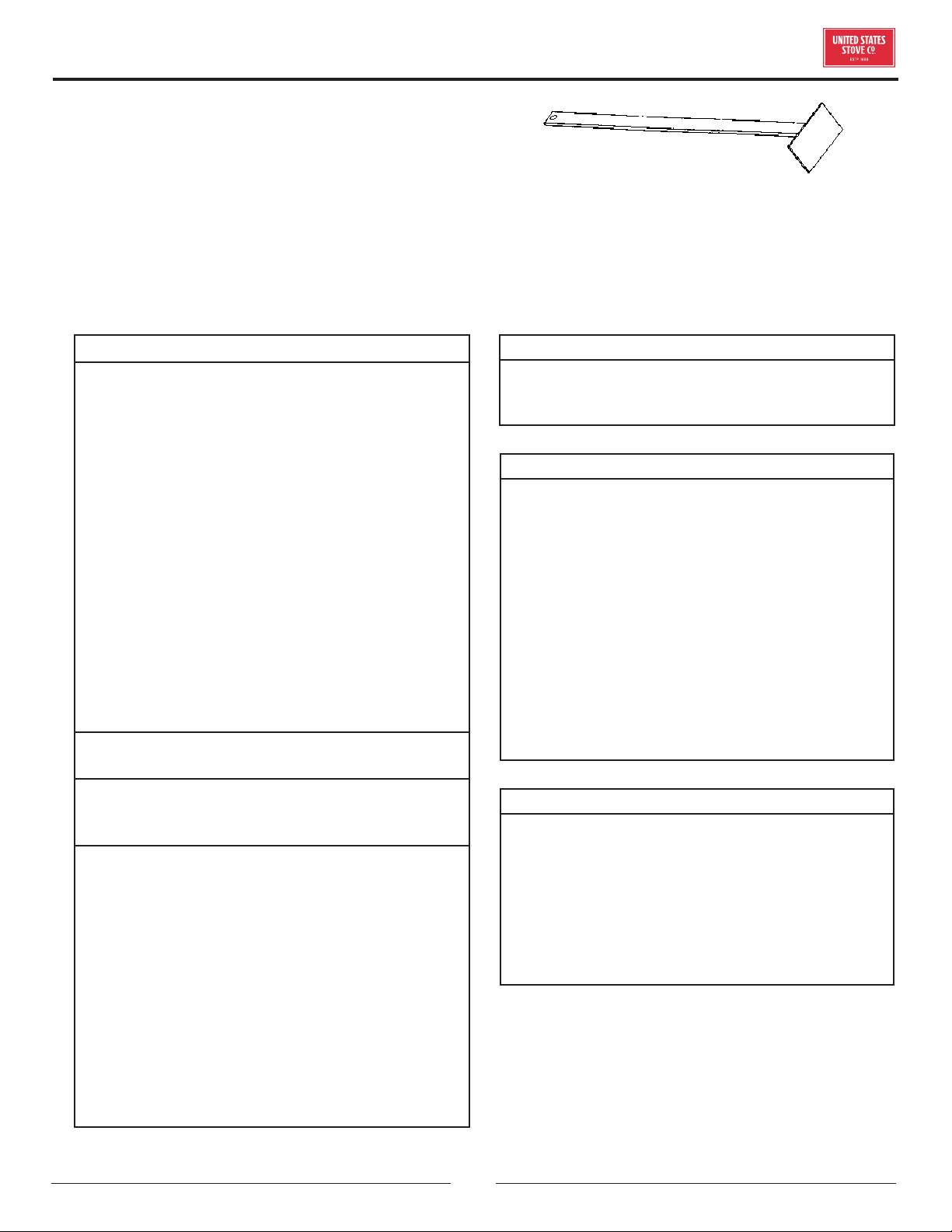
ASSEMBLY FACADE (SURROUND)
Remove contents from packaging and make sure you
have all components:
(2) Top Facade (a)
(1) Left Side Facade (b)
(1) Right Side Facade (c)
(4 pieces)Facade Trim Kit (d)
(1) Feed Door Spring Handle (e)
(1) Damper Spring Handle (f)
(1) Ash Pan “U” shaped Handle (g)
(1) Access Door Knob (h)
(1) PCB Cover (i)
(1) Panel Cover (j)
(1) Auger (in ash pan)
(1) Power Cord
(1) Burnpot Poker (k)
(a)
(a)
(c)
(h)
(f)
(g)
(b)
(e)
MOUNTING HARDWARE
Start by mounting either the left or right side facade
pieces to the unit using four(4) of the supplied #10 x 1/2
screws. Then put the two(2) top facade pieces together
with two(2) of the #10 x 1/2 screws provided. Attach the
top facade assembly to the unit with eight(8) of the same
screws.
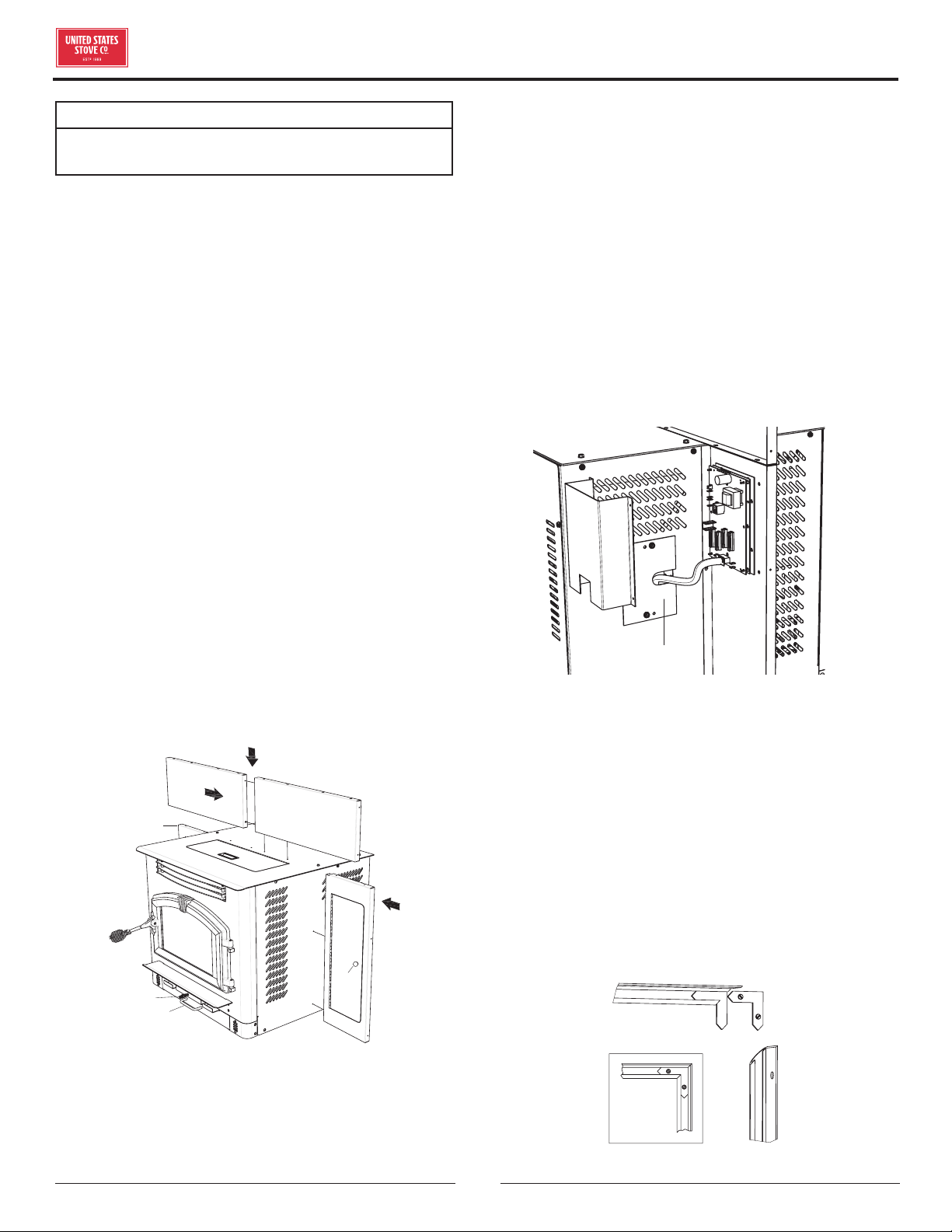
CONTROL BOARD (PCB) RELOCATION
Remove the left side front panel from the unit. While
holding the PCB with one hand, remove the two(2) hex
head screws holding the board in place. It is not necessary
to unplug the PCB cable. Route the board and cable
through the opening and mount it to the Left Facade using
two of the #10 x 1/2 phillips head screws provided. Then
attach the PCB cover to the back of the facade covering
the board. Next, use the two hex head screws removed
earlier and mount the cover panel over the opening where
the PCB was located. See illustration to the left.
(i)
(j)
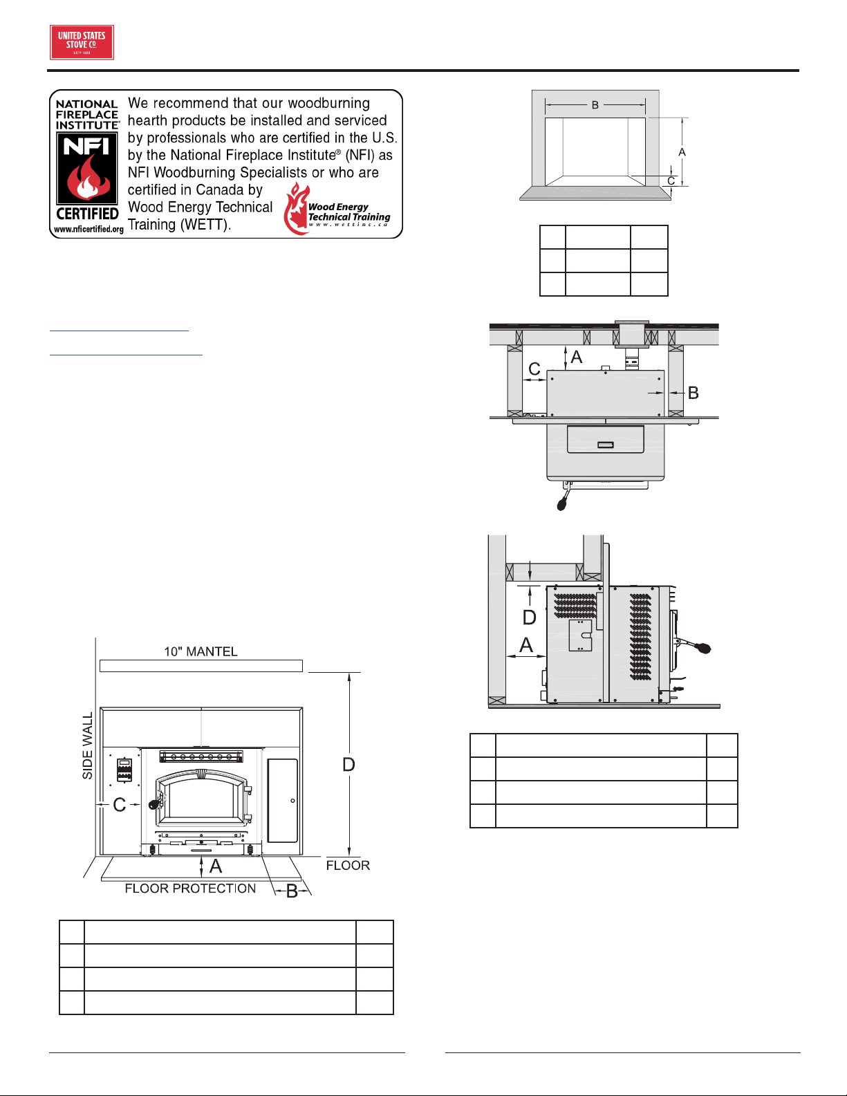
FACADE TRIM
Remove trim from shipping tube. There should be
one(1) left side, one(1) right side, two(2) top pieces, and
mounting hardware. Using one blank corner key and one
corner key with set screws, assemble the left trim and
one of the top pieces together. As illustrated, place the
blank key behind the key with the set screws. Adjust
corners and tighten set screws. Repeat this for the right
sideBefore removing tape, place trim assembly against
facade to get an idea of how it is to be mounted. Remove
the strip from the adhesive and carefully secure the trim
in place by firmly pressing it to the facade.
(d)
© 2021 United States Stove Company
5
SPECIFICATIONS
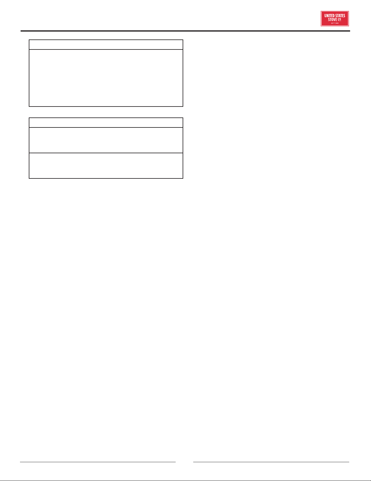
BURNPOT POKER
The burnpot poker may be used several ways. It is used
primarily as a fuel-loading assistant to help push the fuel
to the rear of the hopper for maximum fueling. It may also
be used for cleaning of ashes or removal of clinkers.
VENTILATEUR DE CONVECTION
Quand vous mettez en route votre poêlle, le ventilateur de convection ne va démarrer que lorsque l'échangeur de chaleur du poêle va
chauffer. Ceci prend environ 10 minutes.
REDÉMARRER UN POÊLE CHAUD
Si le poêle n'a pas été en fonctionnement, et que vous voulez le redémarrer pendant qu'il est encore chaud, il faut appuyer de manière
continue sur le bouton «On/Off» pendant 2 secondes.
QUAND LE POÊLE N'A PLUS DE GRANULÉS
Le feu s'éteint et le moteur de la vis sans fin et les ventilateurs vont continuer à fonctionner jusqu'à ce que le poêle refroidisse. Cela peut
prendre 30 à 45 minutes
Après l'arrêt des éléments du poêle, les voyants «On/Off» et du graphique à barres restent allumés pendant une dizaine de minutes.
Après ces 10 minutes, le voyant «3» du graphique à barres va clignoter et le voyant «On/Off» va s'éteindre.
Pour redémarrer, remplir la trémie et appuyer sur le bouton «Fuel Feed» jusqu'à ce que les granulés commencent à tomber dand le foyer.
Appuyez sur le bouton «On/Off».
ALIMENTATION EN GRANULÉS
Nous recommandons de ne pas laisser le foyer rempli à moins d'1/4.
LAISSEZ LE COUVERCLE DE LA TRÉMIE FERMÉ TOUT LE TEMPS, SAUF PENDANT LE REMPLISSAGE. NE PAS TOP REMPLIR
LA TRÉMIE.
OUTILS D'ENTRETIEN BRECKWELL
Un outil est fourni, qui permet:
a. La répartition des granulés dans la trémie – contrairement aux liquides dans un réservoir, les granulés ne se répartissent pas
régulièrement dans la vis sans fin. Sinon, voici ce qui peut se produire. Les granulés peuvent rester suspendus sur les côtés de la
trémie. Le fait de «répartir» les granulés peut améliorer la situation.
NOTE: Pour prévenir le débordement des granulés, on peut coller du papier ciré sur les parois latérales et le fond de la trémie.
b. Nettoyage des tuyaux d'échange de chaleur – voir «NETTOYAGE».
c. Raclez les cendres du foyer.
PROCÉDURE D'ARRÊT
Pour arrêter votre poêle Breckwelll, il suffit d'appuyer sur le bouton «On/Off» du panneau de contrôle. La lumière verte va s'éteindre. Les
ventilateurs vont continuer à fonctionner jusqu'à ce que la température des éléments internes redescende en dessous d'un seuil prédéfini.
COMPOSANTS DE SÉCURITÉ
a. Votre poêle est équipé d'un thermodisque haute température. Cet interrupteur de sécurité a deux fonctions.
1. Pour reconnaître une situation de surchauffe du poêle et arrêter l'alimentation en granulés ou le système de vis sans fin.
2. S'il y a une anomalie au niveau du ventilateur de convection, le thermodisque de haute température va automatiquement arrêter
la vis sans fin, empêchant la surchauffe du poêle.
NOTE: Sur certains modèles, quand ils sont activés, comme un fusible, il faudra appuyer sur le bouton «Reset» avant de redémarrer le
poêle. Sur d'autres modèles, le thermodisque n'a pas de bouton «Reset» et ne se débrayera que quand le poêle aura refroidi. Le
fabricant recommande que vous appeliez votre revendeur si ça arrive, car cela peut cacher un problème plus grave. Il se peut qu'un
appel au service après-vente soit nécessaire.
b. Si le ventilateur de combustion fait défaut, un interrupteur de pression d'air va arrêter automatiquement la vis sans fin.
NOTE: Si on ouvre la porte du poêle pendant plus de 30 secondes quand il est en service, ceci entraînera une différence de
pression suffisante pour activer le bouton d'aération et fermer l'arrivée de combustible. Fermer la porte et appuyer sur le
bouton «On/Off» pour continuer à faire marcher le poêle.
FIGURE 20
FONCTIONNEMENT 17
SAFETY NOTICE
• IF THIS STOVE IS NOT PROPERLY INSTALLED,
A HOUSE FIRE MAY RESULT. TO REDUCE THE
RISK OF FIRE, FOLLOW THE INSTALLATION
INSTRUCTIONS.
• CONTACT YOUR LOCAL BUILDING OFFICIALS TO
OBTAIN A PERMIT AND INFORMATION ON ANY
ADDITIONAL INSTALLATION RESTRICTIONS
OR INSPECTION REQUIREMENTS IN YOUR
AREA.
• DO NOT PLACE CLOTHING OR OTHER
FLAMMABLE ITEMS ON OR NEAR THIS STOVE.
• NEVER USE GASOLINE, GASOLINE-TYPE
LANTERN FUEL, KEROSENE, CHARCOAL
LIGHTER FLUID, OR SIMILAR LIQUIDS TO
START OR ’FRESHEN UP’ A FIRE IN THIS STOVE.
KEEP ALL SUCH LIQUIDS WELL AWAY FROM
THE STOVE WHILE IT IS IN USE.
• DO NOT CONNECT THIS HEATER TO “B” VENT.
USE UL LISTED PELL VENT ONLY!
• DO NOT ELEVATE THE FIRE BY USE OF GRATE
OR ANY OTHER MEANS OTHER THAN THE
SUPPLIED BURNPOT.
• YOUR STOVE REQUIRES PERIODIC
MAINTENANCE AND CLEANING (SEE
”MAINTENANCE”). FAILURE TO MAINTAIN
YOUR STOVE MAY LEAD TO IMPROPER AND/OR
UNSAFE OPERATION.
• ALWAYS ROUTE THE POWER CORD AWAY
FROM THE UNIT. DO NOT ROUTE CORD IN
FOOT TRAFFIC AREAS. DO NOT PINCH CORD
UNDER FURNITURE. DO NOT ROUTE THE CORD
ACROSS THE EXHAUST PIPE.
• A POWER SURGE PROTECTOR IS REQUIRED.
THE UNIT MUST BE PLUGGED INTO A
GROUNDED 110-VOLT POWER SOURCE.
CAUTION:
BURNING FUEL CREATES CARBON MONOXIDE
AND CAN BE HAZARDOUS TO YOUR HEALTH IF
NOT PROPERLY VENTED.
ATTENTION:
• A WORKING SMOKE DETECTOR MUST BE
INSTALLED IN THE SAME ROOM AS THIS
PRODUCT.
• INSTALL A SMOKE DETECTOR ON EACH FLOOR
OF YOUR HOME; INCASE OF ACCIDENTAL FIRE
FROM ANY CAUSE IT CAN PROVIDE TIME FOR
ESCAPE.
• THIS HEATER IS NOT INTENDED FOR USE IN
COMMERCIAL INSTALLATIONS.
• THIS PRODUCT REQUIRES SIMPLE PERIODIC
MAINTENANCE FOR PROPER OPERATION AND
LONG LIFE OF THE HEATER. READ AND FOLLOW
THE MAINTENANCE SCHEDULE CLOSELY.
CAUTION:
• DO NOT UNPLUG THE STOVE IF YOU SUSPECT
A MALFUNCTION. TURN THE ON/OFF SWITCH
TO ”OFF’ AND CONTACT YOUR DEALER.
• THE HEATER WILL NOT OPERATE DURING A
POWER OUTAGE. IF A POWER OUTAGE DOES
OCCUR, CHECK THE HEATER FOR SMOKE
SPILLAGE AND OPEN A WINDOW IF ANY
SMOKE SPILLS INTO THE ROOM.
INSTALLATION
FOR CUSTOMER SERVICE CALL: 8007502723 EXT 5050
6
© 2021 United States Stove Company
INSTALLATION
US Stove highly recommends your stove be installed by a
qualified NFI (US) or WETT (Canada) technician. To find
the nearest qualified installer, go to:
https://nficertified.org,
https://www.wettinc.ca/
INSTALLATION CONFIGURATIONS
This insert may be installed as follows:
1. In a pre-fab firebox (Factory Built)
2. In an existing masonry fireplace
3. As a build-in
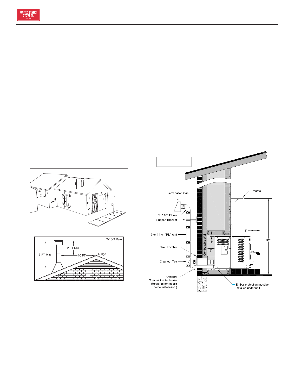
FLOOR PROTECTION
This heater may be installed on a combustible floor, with
proper floor protection, or on a masonry hearth. The
hearth or noncombustible floor protector must extend a
minimum of 6” (152mm) in front and 6” (152mm) from
each side of the unit.
A FLOOR PROTECTOR TO FRONT OF UNIT 6”
B FLOOR PROTECTOR TO SIDE OF UNIT 6”
C LEFT SIDE OF UNIT TO WALL 8”
D FLOOR TO MANTEL 53”
A HEIGHT 24”
B WIDTH 40”
C DEPTH 20”
A BACK OF UNIT TO WALL 6”
B RIGHT SIDE OF UNIT TO WALL 1”
C LEFT SIDE OF UNIT TO WALL 6”
D TOP OF UNIT TO WALL 1”
OUTSIDE AIR SUPPLY (OPTIONAL, UNLESS
INSTALLING IN A MOBILE HOME)
Depending on your location and home construction,
outside air may be necessary for optimal performance.
Your stove is approved to be installed with an outside air
intake (69FAK) which is necessary for a mobile home.
You can purchase the 69FAK through your heater dealer.
Installation instructions are supplied with the air intake
kit.
© 2021 United States Stove Company
7
INSTALLATION
ATTENTION:
DO NOT VENT UNDER ANY PORCH, DECK,
AWNING, OR IN ANY SEMI ENCLOSED OR
ROOFED AREA. DOING SO MAY RESULT IN
UNPREDICTABLE AIRFLOW AT THE VENT CAP
UNDER CERTAIN CONDITIONS AND CAN AFFECT
THE PERFORMANCE OF YOUR STOVE, AS WELL
AS OTHER UNFORESEEABLE ISSUES.
WARNING! DO NOT INSTALL IN SLEEPING ROOM.
CAUTION! THE STRUCTURAL INTEGRITY OF THE
MOBILE HOME FLOOR, WALL, AND CEILING/ROOF
MUST BE MAINTAINED.
WHEN INSTALLED IN A MOBILE HOME, THE STOVE
MUST BE GROUNDED DIRECTLY TO THE STEEL
CHASSIS AND BOLTED TO THE FLOOR.
In addition to the previously detailed installation
requirements, mobile home installations must meet the
following requirements:
• This stove must be securely fastened to the floor of
the mobile home using two 1/4” lag bolts that are long
enough to go through both a hearth pad, if used, and
the floor of the home.
• The heater must be electrically grounded to the steel
chassis of the mobile home with 8 GA copper wire
using a serrated or star washer to penetrate paint or
protective coating to ensure grounding.
• Vent must be 3 or 4-inch “PL” Vent and must extend
a minimum or 36” (914 mm) above the roof line of the
mobile home and must be installed using a certified
ceiling fire stop and rain cap.
• When moving your mobile home, all exterior venting
must be removed while the mobile home is being
relocated. After relocation, all venting must be
reinstalled and securely fastened.
• Outside Air is mandatory for mobile home installation.
See Outside Air Supply section and your dealer for
purchasing.
• Check with your local building ocials as other codes
may apply.
INSTALL VENT AT CLEARANCES
SPECIFIED BY THE VENT MANUFACTURER.
• A UL listed 3” or 4” type “PL” pellet vent exhaust
system must be used for installation and attached to
the pipe connector provided on the back of the heater.
Use a 3” to 4” adapter for 4” pipe. A 4” PL is required
for elevations above 2,500 feet above sea level.
• Do not terminate vent in any enclosed or semi-enclosed
area, such as; carports, garage, attic, crawl space, under
a sundeck or porch, narrow walkway or close area, or
any location that can build up a concentration of fumes
such as a stairwell, covered breezeway etc.
• Vent surfaces can get hot enough to cause burns if
touched by children. Noncombustible shielding or
guards may be required.
• Do not install a flue damper in the exhaust vent of this
unit.
• Termination must exhaust above air inlet elevation.
Installation MUST include three (3) vertical feet of
pellet vent pipe. This will create some natural draft
to prevent the possibility of smoke or odor during
appliance shutdown and to keep exhaust from causing
a nuisance or hazard from exposing people or shrubs
to high temperatures. Do not connect this unit to a
chimney flue serving another appliance. Do not connect
directly to a masonry chimney.
• The installation must include a cleanout tee to enable
collection of fly ash and to permit periodic cleaning of
the exhaust system. 90° elbows accumulate fly ash and
soot thereby reducing exhaust flow and performance of
the heater. Each elbow or tee reduces draft potential by
30% to 50%. Use no more than 180 degrees of elbows
(two 90° elbows, or two 45° and one 90° elbow, etc.)
and one cleanout tee to maintain adequate draft.
Cleanout tees and elbows should not be connected to
the rear of the unit unless a 3-inch adapter is used.
• Total length of horizontal vent must not exceed 48”
(4ft.)/1,200mm. The maximum recommended vertical
venting height is 12-feet for 3-inch type “PL” vent. For
venting higher than 12-feet, 4-inch “PL” vent must be
used. All joints in the vent system must be fastened
by at least 3 screws, and all joints must be sealed with
RTV silicone sealer to be airtight.
• The area where the vent pipe penetrates to the exterior
of the home must be sealed with silicone or other means
to maintain the vapor barrier between the exterior and
the interior of the home.
NOTE: These are guidelines only. Proper venting is
accomplished by design and necessary requirements. In
most installations 3 inch diameter venting is adequate.
If it does not vent properly you will have to change it to 4
inches. You should not exceed 4 inch diameter venting.
DO NOT CONNECT TO ANY AIR DISTRIBUTION DUCT
OR SYSTEM
8
© 2021 United States Stove Company
INSTALLATION
IMPORTANCE OF PROPER DRAFT
Draft is the force which moves air from the appliance
up through the chimney. The amount of draft in your
chimney depends on the length of the chimney, local
geography, nearby obstructions and other factors. Too
much draft may cause excessive temperatures in the
appliance. Inadequate draft may cause backpung into
the room and ‘plugging’ of the chimney. Inadequate draft
will cause the appliance to leak smoke into the room
through appliance and chimney connector joints. An
uncontrollable burn or excessive temperature indicates
excessive draft. Take into account the chimney’s location
to ensure it is not too close to neighbors or in a valley
which may cause unhealthy or nuisance conditions. It
is recommended that only an authorized installer install
your heater, preferably an NFI certified specialist. The
following installation guidelines must be followed to
ensure conformity with both the safety listing of this
heater and to local building codes.
VENT TERMINATION CLEARANCES
D. Min. 4-ft clearance below or beside any door or
window that opens.
E. Min. 1-ft clearance above any door or window that
opens.
F. Min. 3-ft clearance from any adjacent building.
G. Min. 7-ft clearance from any grade when adjacent to
public walkways.
H. Min. 2-ft clearance above any grass, plants, or other
combustible materials.
I. Min. 3-ft clearance from a forced air intake of any
appliance.
J. Min. 2-ft clearance below eaves or overhang.
K. Min. 1-ft clearance horizontally from combustible
wall.
L. Must be a minimum of 36-inches above the roof and
24-inches above the highest point or the roof within
10-feet.
INSTALLATION AS A BUILTIN FIREPLACE
A continuous sheet of non-combustible floor protection
must be installed underneath the unit to prevent the
possibility of embers falling through to the combustible
floor. If the floor beneath the unit is of non-combustible
material, the protector is not required. See the “Clearance
to Combustibles” section of this manual for installation
clearances.
A MINIMUM OF 3 VERTICAL
FEET OF PIPE OUTSIDE THE
HOME IS REQUIRED!
ALTERNATIVE EXHAUST VENTING
Depending on your installation, you might consider
routing your cleanout tee as illustrated below for ease
of cleaning. The access panel in the right side facade
allows you to reach the tee from the front side of the unit
if venting is assembled as shown. The cleanout tee is
attached to a 90° elbow mounted to the unit then rotated
at approx. 15-20 degrees. A 12 inch section of “PL” vent is
connected to reach the top of the unit to which a flexible
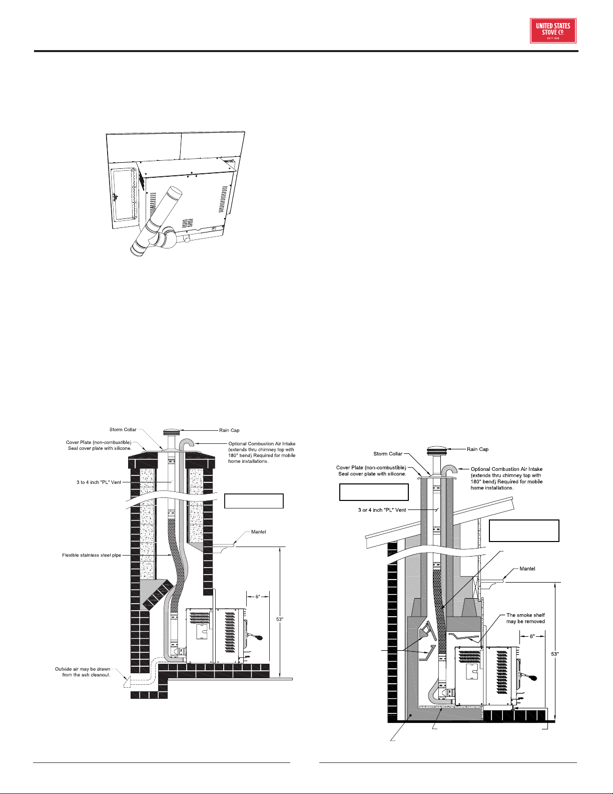
© 2021 United States Stove Company
9
INSTALLATION
pipe may be attached for further termination through a
chimney. Clearance to combustibles must be considered
if this installation is chosen. A distance of 3 inches must
be maintained from the exhaust vent to any combustible
material.
INSTALLATION INTO A MASONRY
FIREPLACE
(4” Pell Vent “PL” Piping) that extends the full height of
the chimney and meets type HT requirements. The liner
must be securely attached to the insert and the chimney
top. The chimney must be sealed either at the top or at
the damper area with a non-combustible plate to prevent
room air passage to chimney cavity. Outside combustion
air may be drawn through the chimney top or through an
existing ash cleanout.
4” VENT IS MANDATORY FOR
INSERT INSTALLATIONS.
When installing into a masonry fireplace, DO NOT remove
any bricks or masonry, with the following exception:
masonry or steel, including the damper plate, may be
removed from the smoke shelf and adjacent damper
frame, if necessary, to accommodate a chimney liner. Do
this only if their removal will not weaken the structure
of the fireplace or the chimney, and will not reduce
protection for combustibles to less than that required
by national building codes. Installation must include a
chimney liner.
INSTALLATION INTO A FACTORYBUILT
(METAL) FIREPLACE
When installing into a zero clearance fireplace, The
firebox must accept the insert without modification other
than removing bolted or screwed together pieces such as
smoke shelf/deflectors, ash lips, screen or door tracks,
and damper assemblies. These items must be re-installed
if the insert is removed and not replaced. The removal of
any part must not alter the integrity of the listed fireplace
in any way. The factory built fireplace must be listed
per UL 127. Installation must include a chimney liner
(4” Pell Vent “PL” Piping) that extends the full height of
the chimney and meets type HT requirements. The liner
must be securely attached to the insert and the chimney
top. The chimney must be sealed either at the top or at
the damper area with a non-combustible plate to prevent
room air passage to chimney cavity. For raised hearth
installations, adjust the leveling bolts under the front of
the unit.
The metal sides, frame members, or other structural components of
the factory-built replace may not be removed or altered.
The masonry lining
may not be removed.
The Damper and
Internal Baes
may be removed
Flexible Stainless
Steel Pipe
Adjust Leveling Bolts
for raised replaces
NOTE: The Log Shelf, Screen,
and Doors (if present) must
be removed.
4” VENT IS MANDATORY FOR
INSERT INSTALLATIONS.
10
© 2021 United States Stove Company
OPERATION INSTRUCTIONS
NEVER OPERATE THIS PRODUCT WHILE UNATTENDED
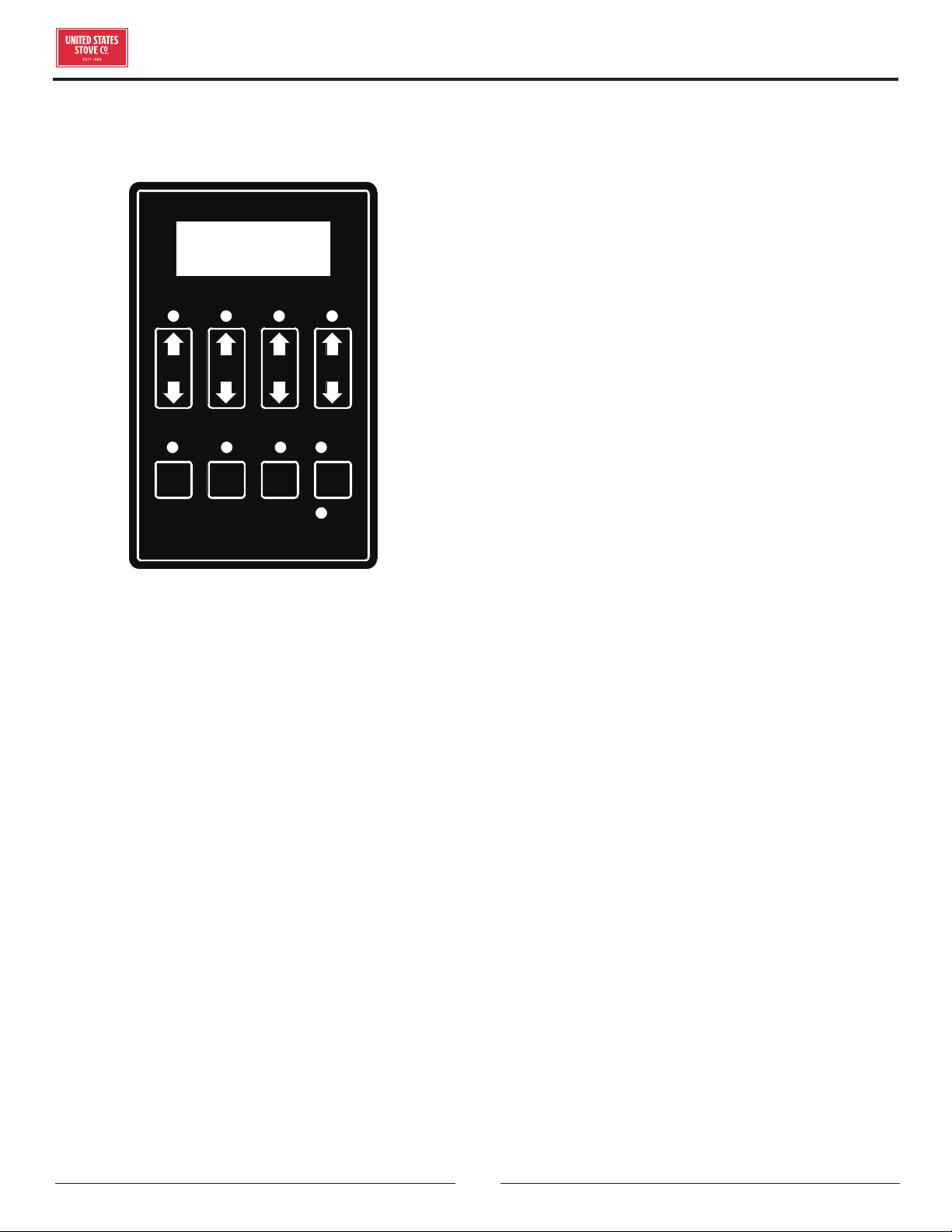
UNDERSTANDING THE CONTROL BOARD
ON OFF
Auger
Delay
Mode
Auto
Manual
Heat
Range
Room
Fan
Draft
Fan
Aux.
Turning the heater OFF/ON, as well as adjustments for
the fuel feed rate and room fan speed are performed by
pressing the appropriate button(s) on the control panel.
This unit has two fuel operation modes. It may also be
changed between an automatic operation or a manual
operation in either of the fuel modes.
• Pressing the “ON” button on the control panel will
begin the start-up sequence for the heater. The start-
up sequence diers depending on which fuel operation
mode you select (see Lighting Instructions for details).
Pressing and holding the “ON” button will rotate the
auger continuously until the button is released, which
feeds additional fuel.
• Pressing the “OFF” button on the control panel will
cause the heater to enter its shut-down sequence. The
fuel feed system will stop pulling fuel from the hopper
and, once the fire goes out and the heater cools down,
the fans will stop running.
• Pressing the “Heat Range” arrows, up or down, will
adjust the amount of fuel being delivered to the burnpot.
• The draft fan (exhaust) will come on as soon as the
“ON” button is pressed. The fan will automatically
adjust its speed in accordance to the heat range setting.
However, this speed can be manually operated by
pressing the “Draft Fan” arrows up or down. “Draft Fan”
when pressed, the display will show “DF-A”, which is
automatic. Press the arrows again to adjust fan speed.
When adjusting the draft fan setting, try only
• One setting above or below the heat setting. It is better
to leave the heater in the automatic mode and adjust
the manual draft slide to control the combustion air.
• The room fan will come on once the unit has reached
operating temperature (approx. 110°F). By pressing
the “Room Fan” buttons, the display will show “RF-
A” which is automatic or “RF-1” through “RF-9” for
manual settings. In auto mode, the room fan’s speed will
automatically be adjusted in accordance with the heat
range setting. By pressing the “Room Fan” up arrow,
you can adjust the fan speed setting up to “RF-9”. The
fan speed can be adjusted to a higher setting than the
heat setting but not lower than the corresponding heat
range.
• The “Aux” button is for Agitator operation. When
the unit is “OFF” and the heater is cool, pressing the
“Aux” arrows will rotate the agitator for easy removal
for cleaning. The agitator, when in Automatic mode,
will operate at set intervals. However, these can be
changed by pressing the arrows on the “Aux” button.
The agitator can be adjusted from 0 to 9, setting “0” is
o and setting “9” is high.
• The “Auger Delay” button can be used to pause rotation
of the Auger and Agitator for approx. 1 minute. This can
be cancelled by pressing the “ON” button. The “Auger
Delay” is normally used only during the start up cycle
to slow the fuel delivery down during the initial ignition.
• The “Mode” button is used to switch between manual
and automatic mode. When in auto mode, the fan,
auger, and agitator will operate at preset intervals
unless changed manually using the buttons mentioned
above. When in manual mode, the draft fan (exhaust)
will operate at full speed (100%), so the air must be
controlled with the manual slide damper just below the
viewing door. When the heater is in the manual mode,
the optional thermostat will not properly control the
unit.
• During normal operation, the unit is constantly
monitored for problems. In the event of an error
condition, the unit will stop and an error will be
displayed. See the list of error codes found at the end
of this manual.
© 2021 United States Stove Company
11
OPERATION INSTRUCTIONS
WARNING:
• DO NOT USE CHEMICALS OR FLUIDS TO START
THE FIRE - NEVER USE GASOLINE, GASOLINE-
TYPE LANTERN FUEL, KEROSENE, CHARCOAL
LIGHTER FLUID, OR SIMILAR LIQUIDS TO START
OR “FRESHEN UP” A FIRE IN THIS STOVE. KEEP
ALL SUCH LIQUIDS WELL AWAY FROM THE
STOVE WHILE IT IS IN USE.
• HOT WHILE IN OPERATION. KEEP CHILDREN,
CLOTHING AND FURNITURE AWAY. CONTACT
MAY CAUSE SKIN BURNS.
DO NOT BURN:
1. Garbage;
2. Lawn clippings or yard waste;
3. Materials containing rubber, including tires;
4. Materials containing plastic;
5. Waste petroleum products, paints or paint thinners,
or asphalt products;
6. Materials containing asbestos;
7. Construction or demolition debris;
8. Railroad ties or pressure-treated wood;
9. Manure or animal remains;
10. Salt water driftwood or other previously salt water
saturated materials;
11. Unseasoned wood; or
12. Paper products, cardboard, plywood, or particleboard.
The prohibition against burning these materials does
not prohibit the use of fire starters made from paper,
cardboard, saw dust, wax and similar substances
for the purpose of starting a fire in an aected wood
heater.
Burning these materials may result in release of toxic
fumes or render the heater ineective and cause smoke.
PROPER FUEL
ATTENTION:
THIS APPLIANCE IS DESIGNED FOR THE USE OF
PELLETIZED FUEL THAT MEET OR EXCEED THE
STANDARD SET BY THE PELLET FUEL INSTITUTE
(PFI).
Your pellet stove is designed to burn premium hardwood
pellets that comply with the Pellet Fuels Institute (PFI)
standard (minimum of 40 lbs density per cubic ft, 1/4” to
5/16” diameter, length no greater than 1.5”, not less than
8,200 BTU/lb, moisture under 8% by weight, ash under
1% by weight, and salt under 300 parts per million).
Pellets that are soft, contain excessive amounts of loose
sawdust, have been, or are wet, will result in reduced
performance. Store your pellets in a dry place. DO NOT
store the fuel within the installation clearances of the
unit or within the space required for refuelling and ash
removal. Doing so could result in a house fire. Do not over
fire or use volatile fuels or combustibles, doing so may
cause a personal and property damage hazards.
THIS STOVE IS APPROVED FOR BURNING PELLETIZED
WOOD FUEL ONLY ! Factory-approved pellets are those
1/4” or 5/16” in diameter and not over 1” long. Longer or
thicker pellets sometimes bridge the auger flights, which
prevents proper pellet feed. Burning wood in forms other
than pellets is not permitted. It will violate the building
codes for which the stove has been approved and will
void all warranties. The design incorporates automatic
feed of the pellet fuel into the fire at a carefully prescribed
rate. Any additional fuel introduced by hand will not
increase heat output but may seriously impair the stoves
performance by generating considerable smoke. Do
not burn wet pellets. The stove’s performance depends
heavily on the quality of your pellet fuel. Avoid pellet
brands that display these characteristics:
• Excess Fines – “Fines” is a term describing crushed
pellets or loose material that looks like sawdust or sand.
Pellets can be screened before being placed in hopper
to remove most fines.
• Binders – Some pellets are produced with materials to
hold the together, or “bind” them.
• High ash content – Poor quality pellets will often create
smoke and dirty glass. They will create a need for more
frequent maintenance. You will have to empty the burn
pot plus vacuum the entire system more often. Poor
quality pellets could damage the auger. We cannot
accept responsibility for damage due to poor quality
pellet.
CAUTION:
• KEEP FOREIGN OBJECTS OUT OF THE HOPPER.
• THE MOVING PARTS OF THIS STOVE ARE
PROPELLED BY HIGH TORQUE ELECTRIC
MOTORS. KEEP ALL BODY PARTS AWAY FROM
THE AUGER WHILE THE STOVE IS PLUGGED
INTO AN ELECTRICAL OUTLET. THESE MOVING
PARTS MAY BEGIN TO MOVE AT ANY TIME
WHILE THE STOVE IS PLUGGED IN.

12
© 2021 United States Stove Company
OPERATION INSTRUCTIONS
PRESTARTUP CHECK
Remove burn pot, making sure it is clean and none of the
air holes are plugged. Clean the firebox, and then reinstall
burn pot. Clean door glass if necessary (a dry cloth or
paper towel is usually sucient). Never use abrasive
cleaners on the glass or door. Choose which fuel setting
that you wish to operate in. Do this by first pressing
the “ON” button, then press the “Heat Range” Up and
Down arrows together for approximately 3-4 seconds
and release. A “C” or “P” in the first digit of the display
will indicate the mode. The “ON” led will be blinking and
the display will show “CR-1” or “PR-1”, depending on the
mode. The “Heat Range” indicator LED and the “Auto”
LED should be lit and the dash in the Heat Range display
should be flashing. You will notice the draft fan starts
immediately. If you press the “Heat Setting” button up, the
draft fan changes speed, increasing speed the higher the
heat setting. You should begin to see the igniter, located
in the center and behind the burnpot, begin to glow after
a short period of time. In CR-1, the auger and agitator will
start rotating after a few minutes, allowing for proper fuel
ignition. In PR-1, the auger will turn immediately, then
the agitator will begin to rotate once the heater reaches
operating temperature. Note: The room fan will not
operate at this time, as a temperature of at least 110°F
must be reached before operating. If proper operation of
your heater is confirmed, press the “OFF” button, then fill
your hopper with fuel. Ensure there is no foreign matter in
your fuel, hopper or burnpot.
BUILDING A FIRE
Never use a grate or other means of supporting the fuel.
Use only the burn pot supplied with this heater. Hopper
lid must be closed in order for the unit to feed pellets.
During the start-up period:
• Make sure the burn pot is free of pellets.
• DO NOT open the viewing door.
• DO NOT add pellets to the burn pot by hand.
NOTE: During the first few fires, your stove will emit an
odor as the high-temperature paint cures or becomes
seasoned to the metal. Maintaining smaller fires will
minimize this. Avoid placing items on the stovetop during
this period because the paint could be aected. Attempts
to achieve heat output rates that exceed heater design
specifications can result in permanent damage to the
heater.
IGNITOR
• Close all doors, lids, and cleanouts.
• Press the “ON” button and select desired heat range.
This will start the ignition sequence.
• At this point, the igniter will come on and run for preset
time limit (approximately 9 minutes). The auger will
begin to turn and feed fuel into the burnpot. After the 9
minutes or if the heater reaches operating temperature,
the igniter will shut o and normal operation will begin.
• Make fine adjustments to the air/fuel with the damper
located centered, under the hearth.
• Once the heater reaches warm temperature, the room
fan will start to circulate air into the room.
• If you would like to increase the life of your ignitor, you
can run your heater in the “CR” mode. However, you
must place pellets in the burnpot, up to the igniter level
as shown in the illustration below for auto ignition.
Close the door and press the “ON” button. The igniter
only runs approximately half the time in “CR” as oppose
to the “PR” mode.
OPENING DOOR
CAUTION:
• DO NOT OPERATE YOUR STOVE WITH THE
VIEWING DOOR OPEN. THE AUGER WILL NOT
FEED PELLETS UNDER THESE CIRCUMSTANCES
AND A SAFETY CONCERN MAY ARISE FROM
SPARKS OR FUMES ENTERING THE ROOM.
• THE DOOR MUST BE CLOSED AND SEALED
DURING OPERATION.
If the door is opened while the stove is in operation it
must be closed within 30 seconds or the stove will shut
down. If the stove shuts down push the “On/O” button
to re-start your stove. The stove will have to fully shut
down and turn o before you will be able to restart the
stove.
TAMPER WARNING
This wood heater has a manufacturer-set minimum low
burn rate that must not be altered. It is against federal
regulations to alter this setting or otherwise operate this
wood heater in a manner inconsistent with operating
instructions in this manual.
© 2021 United States Stove Company
13
OPERATION INSTRUCTIONS
REFUELLING
CAUTION:
• THE HOPPER AND STOVE TOP WILL BE HOT
DURING OPERATION; THEREFORE, YOU
SHOULD ALWAYS USE SOME TYPE OF HAND
PROTECTION WHEN REFUELING YOUR STOVE.
• DO NOT TOUCH THE HOT SURFACES OF THE
STOVE. EDUCATE ALL CHILDREN ON THE
DANGERS OF A HIGH-TEMPERATURE STOVE.
YOUNG CHILDREN SHOULD BE SUPERVISED
WHEN THEY ARE IN THE SAME ROOM AS THE
STOVE.
• NEVER PLACE YOUR HAND NEAR THE AUGER
WHILE THE STOVE IS IN OPERATION.
• WE RECOMMEND THAT YOU NOT LET THE
HOPPER DROP BELOW 1/4 FULL.
WARNING:
• KEEP HOPPER LID CLOSED AT ALL TIMES
EXCEPT WHEN REFILLING.
• DO NOT OVERFILL HOPPER.
SHUTDOWN PROCEDURE
WARNING:
NEVER SHUT DOWN THIS UNIT BY UNPLUGGING
IT FROM THE POWER SOURCE.
Pressing the OFF button will cause the heater to enter
a shutdown mode. If the heater has reached operating
temperature, the “OFF” Indicator will blink until the
shutdown procedure succeeds in lowering the heater
temperature. The Room Fan will stay on to cool the
heater, and the Exhaust Fan will stay on to remove smoke
and heat from the combustion chamber. The Agitator
will rotate continuously until shutdown is complete. The
Auger will bump the fuel out every few seconds to prevent
the fuel in the auger from burning. Once the temperature
of the burn chamber falls below approximately 90°F and
the pressure switch detects that the door is closed, the
fans will stop and the Auger will run for a few seconds to
purge the auger system of any burned fuel. At this point,
the “OFF” Indicator will go out and the heater will turn
completely o. If during burning, the heater reached at
least 120°F, the shutdown procedure will include a 15
minute shutdown cycle that will keep the heater in the
shutdown state for at least 15 minutes regardless of
whether it is cool or pressure is detected. The 15 minute
cycle can be turned o by pressing the o button during
shutdown. This will cause the system to exit shutdown
and return to the “OFF” mode as soon as the door is
closed and the heater is cool. Continue to monitor the
heater / insert after the shutdown procedure has begun.
And remember, varying ambient conditions may result
in a lengthy period of time for adequate cool down and
the resultant shut down. Be patient, this is normal. The
control board is telling the heater / insert to gradually
“shut down,” rather than initiate a sudden halt of fuel to
the fire pot. In this way, the possibility of smoke entering
the home is avoided.
INTERIOR CHAMBERS
• Periodically remove and clean the burn pot and the area
inside the burn pot housing. In particular, it is advisable
to clean out the holes in the burn pot to remove any
build up that may prevent air from moving through the
burn pot freely.
• Remove the small clean-out slides in the lower corners
of the firebox. Tap the sides of the burn chamber with
a wooden stick. Do not tap the firewall behind the burn
box as it may damage the ceramic firebrick. Scrape the
fly ash from the clean-out chambers toward the front
of the burn chamber. Remove the fly ash from the burn
chamber and replace the clean-outs.
• Remove the ash pan and dump the ash into a metal
container.
• Cleaning of the exhaust system will depend upon the
ash and debris content of your fuel. If your fuel has a
high ash content and/or significant debris in it, your
exhaust system will require weekly cleaning. Cleaner
fuels will allow for monthly cleaning of the exhaust
system. Remove the exhaust pipe from the back of your
heater and remove any ash that may have collected in
the pipes. Replace the pipes to the heater and seal with
high temperature seal tape. If you have installed proper
clean out tees you will not have to take the chimney
sections apart.
14
© 2021 United States Stove Company
NEVER OPERATE THIS PRODUCT WHILE UNATTENDED
MAINTENANCE
CAUTION:
• FAILURE TO CLEAN AND MAINTAIN THIS
UNIT AS INDICATED CAN RESULT IN POOR
PERFORMANCE, SAFETY HAZARDS, FIRE, AND
EVEN DEATH.
• NEVER PERFORM ANY INSPECTIONS,
CLEANING, OR MAINTENANCE ON A HOT
STOVE.
• DISCONNECT THE POWER CORD BEFORE
PERFORMING ANY MAINTENANCE! NOTE:
TURNING THE ON/OFF SWITCH TO ”OFF”
DOES NOT DISCONNECT ALL POWER TO THE
ELECTRICAL COMPONENTS OF THE STOVE.
• DO NOT OPERATE STOVE WITH BROKEN GLASS,
LEAKAGE OF FLUE GAS MAY RESULT.
• ATTEMPTS TO ACHIEVE HEAT OUTPUT
RATES THAT EXCEED HEATER DESIGN
SPECIFICATIONS CAN RESULT IN PERMANENT
DAMAGE TO THE HEATER.
CREOSOTE FORMATION, INSPECTION, &
REMOVAL
CAUTION:
THE EXHAUST SYSTEM SHOULD BE CHECKED
MONTHLY DURING THE BURNING SEASON FOR
ANY BUILD-UP OF SOOT OR CREOSOTE.
When any wood is burned slowly, it produces tar and
other organic vapors, which combine with expelled
moisture to form creosote. The creosote vapors condense
in the relatively cool chimney flue or a newly started
fire or from a slow-burning fire. As a result, creosote
residue accumulates on the flue lining. When ignited, this
creosote makes an extremely hot fire, which may damage
the chimney or even destroy the house. Despite their high
eciency, pellet stoves can accumulate creosote under
certain conditions. The chimney connector and chimney
should be inspected by a qualified person annually or per
ton of pellets to determine if a creosote or fly ash build-
up has occurred. If creosote has accumulated, it should
be removed to reduce the risk of a chimney fire. Inspect
the system at the stove connection and at the chimney
top. Cooler surfaces tend to build creosote deposits
quicker, so it is important to check the chimney from
the top as well as from the bottom. The creosote should
be removed with a brush specifically designed for the
type of chimney in use. A qualified chimney sweep can
perform this service. It is also recommended that before
each heating season the entire system be professionally
inspected, cleaned and, if necessary, repaired. To clean
the chimney, disconnect the vent from the stove.
FLY ASH
This accumulates in the horizontal portion of an exhaust
run. Though non-combustible, it may impede the normal
exhaust flow. It should therefore be periodically removed.
ASH REMOVAL & DISPOSAL
CAUTION:
ALLOW THE STOVE TO COOL BEFORE PERFORMING
ANY MAINTENANCE OR CLEANING. ASHES
MUST BE DISPOSED IN A METAL CONTAINER
WITH A TIGHT FITTING LID. THE CLOSED
CONTAINER OF ASHES SHOULD BE PLACED ON
A NON-COMBUSTIBLE SURFACE OR ON THE
GROUND, WELL AWAY FROM ALL COMBUSTIBLE
MATERIALS, PENDING FINAL DISPOSAL.
Remove the ashes periodically to avoid unnecessary ash
build up. Remove ashes when unit has cooled. Ashes
should be placed in a metal container with a tight fitting
lid. The closed container of ashes should be placed on a
noncombustible floor or on the ground, well away from
all combustible materials, pending final disposal. If
the ashes are disposed of by burial in soil or otherwise
locally dispersed, they should be retained in the closed
container until all embers have been thoroughly cooled.
The container shall not be used for other trash or waste
disposal. If combined with combustible substances,
ashes and embers may ignite.
SMOKE & CO MONITORS
Burning wood naturally produces smoke and carbon
monoxide(CO) emissions. CO is a poisonous gas when
exposed to elevated concentrations for extended
periods of time. While the modern combustion systems
in heaters drastically reduce the amount of CO emitted
out the chimney, exposure to the gases in closed or
confined areas can be dangerous. Make sure you stove
gaskets and chimney joints are in good working order
and sealing properly to ensure unintended exposure. It is
recommended that you use both smoke and CO monitors
in areas having the potential to generate CO.
© 2021 United States Stove Company
15
MAINTENANCE
CHECK & CLEAN THE HOPPER
Check the hopper periodically to determine if there is any
sawdust (fines) that is building up in the feed system or
pellets that are sticking to the hopper surface. Clean as
needed.
DOOR & GLASS GASKETS
Inspect the main door and glass window gaskets
periodically. The main door may need to be removed to
have frayed, broken, or compacted gaskets replaced by
your authorized dealer. This unit’s door uses a 1” diameter
rope gasket.
BLOWER MOTORS
Clean the air holes on the motors of both the exhaust
and distribution blowers annually. Remove the exhaust
blower from the exhaust duct and clean out the internal
fan blades as part of your fall start-up. If you have indoor
pets your power motors should be inspected monthly to
make sure they are free of animal hair build up. Animal
hair build up in blowers can result in poor performance or
unforeseen safety hazards.
PAINTED SURFACES
Painted surfaces may be wiped down with a damp cloth.
If scratches appear, or you wish to renew your paint,
contact your authorized dealer to obtain a can of suitable
high-temperature paint.
GLASS
We recommend using a high-quality glass cleaner. Should
a buildup of creosote or carbon accumulate, you may wish
to use 000 steel wool and water to clean the glass. DO
NOT use abrasive cleaners. DO NOT perform the cleaning
while the glass is HOT. Do not attempt to operate the unit
with broken glass. Replacement glass may be purchased
from your U.S. Stove dealer. If the glass is broken, follow
these removal procedures:
1. Once the heater has cooled, remove the door from
the heater.
2. Remove the rope gasket from the door followed by
the nuts holding the glass retainer in place.
3. While wearing gloves, carefully remove any loose
pieces of glass from the door frame.
4. Replace the glass and gasket, making sure the gasket
runs the full perimeter of the glass edge.
5. Re-install the retainer and rope gasket using high-
temperature silicone to adhere the gasket to the door.
6. Never use substitute materials for the glass.
DO NOT abuse the door glass by striking, slamming, or
similar trauma. Do not operate the stove with the glass
removed, cracked, or broken.
FALL START UP
Prior to starting the first fire of the heating season,
check the outside area around the exhaust and air intake
systems for obstructions. Clean and remove any fly ash
from the exhaust venting system. Clean any screens on
the exhaust system and on the outside air intake pipe.
Turn all of the controls on and make sure that they are
working properly. This is also a good time to give the
entire stove a good cleaning throughout.
SPRING SHUTDOWN
After the last burn in the spring, remove any remaining
pellets from the hopper and the auger feed system. Scoop
out the pellets and then run the auger until the hopper
is empty and pellets stop flowing (this can be done by
pressing the “ON” button with the viewing door open).
Vacuum out the hopper. Thoroughly clean the burn pot,
and firebox. It may be desirable to spray the inside of the
cleaned hopper with an aerosol silicone spray if your stove
is in a high humidity area. The exhaust system should be
thoroughly cleaned.
MAINTENANCE SCHEDULE
Use the following as a guide under average use conditions.
Gaskets around door and door glass should be inspected
and repaired or replaced when necessary.
Daily Weekly
Monthly or
as needed
Burn Pot Stirred Empty
Combustion
Chamber
Brushed
Ashes Check Empty
Interior Chambers Vacuumed
Combustion
Blower Blades
Vacuumed
/ Brushed
Convection Blower
Impeller
Vacuumed
/ Brushed
Vent System Cleaned
Gaskets Inspected
Glass Wiped Cleaned
Hopper (end of
season)
Empty &
Vacuumed

16
© 2021 United States Stove Company
START-UP SEQUENCE OF EVENTS
Once the control panel is turned on, a timer begins that will start, stop and continue operation of the heater as a
preset temperature is achieved.
COMPONENT OPERATION START OPERATION END
Draft Fan Starts Immediately
Will continue until shutdown. Shutdown will occur when the
operating temperature is below approx. 90 degrees.
Agitator
Begins to turn once the heater
reaches operating temperature
Will continue intermediately, as determined by the “HEAT
SETTING”, until shutdown.
Auger
In PR-1 mode: Auger turns
immediately.
In CR-1: Three minutes after
starting, the auger will begin to turn
The auger will continue at the feed rate specified by the “HEAT
SETTING”.
NOTE: Safety switches, HI limit and vacuum sensor, must be
activated to continue proper operation.
Room Fan
Begins to run when heater reaches
operating temperature
Will continue to operate until the heater cools down to below
approx. 90 degrees. This may take several hours.
Automatic
Shutdown
If after 15 minutes, the heater has
not reached the preset operating
temperature, the unit will begin to
automatically shut down.
Should the timer expire before the preset operating
temperature is achieved, simply reset the heater by pressing
the “ON” button.
Normal
Operation
If after 15 minutes the preset
operating temperature of approx.
110 degrees is achieved, normal
operation will continue.
Operation will continue until either the heater’s control is to
the “OFF” position, or the operating temperature falls below
approx. 90 degrees. At such time the heater will default to the
“Automatic Shut Down”.
Igniter Starts immediately Will continue operation for a preset time, then shut-o
SHUTDOWN SEQUENCE OF EVENTS
Once the Heater has reached the normal operating temperature and switched to the “OFF” position, the unit will
initiate a slow down, reducing the fuel rate until the heater’s “LOW LIMIT SAFETY” sensor tells the control board it
is safe to shutdown.
COMPONENT SHUTDOWN OPERATION END
Draft Fan
Unchanged operation until preset
“OFF” temperature is achieved.
Continues until the operating temperature falls below approx.
90 degrees. May take several hours.
Agitator
Rotates continuously until preset
“OFF” temperature is achieved.
Continues until the operating temperature falls below approx.
90 degrees.
Auger
Slows down to a reduced fuel setting
until preset “OFF” temperature is
achieved.
The auger will continue at the reduced feed rates until the
operating temperature falls below approx. 90 degrees.
NOTE: Safety switches, HI limit and vacuum sensor, must be
activated to continue proper operation.
Room Fan
Unchanged operation until preset
“OFF” temperature is achieved.
Will continue to operate until the heater cools down to below
approx. 90 degrees. This may take several hours.
Automatic
Shutdown
If the heater’s “HI LIMIT” sensor
snaps open, this will cause an
automatic shutdown. An error code
will be displayed (Err1). NOTE:
“HI LIMIT” errors are usually the
result of operating at the highest
heat setting for long periods of
time, room fan failure or loose wire
connection.
It is rare that the HI LIMIT temperature is reached. However,
should this error occur, let the heater cool down for an hour
then restart.
CONTROL BOARD FUNCTIONS

© 2021 United States Stove Company
17
CAUTION: WHEN PERFORMING ANY INTERNAL ELECTRICAL MAINTENANCE
• MOVING PARTS INSIDE OF THE CABINET MAY CAUSE INJURY. DO NOT OPERATE UNIT WITH PANELS
REMOVED OR OPEN.
• HOT PARTS. DO NOT OPERATE THE UNIT WITH PANEL OPEN.
• RISK OF ELECTRIC SHOCK. DISCONNECT POWER BEFORE SERVICING UNIT.
• IN THE EVENT OF COMPONENT FAILURE, REPLACE WITH THE ORIGINAL FACTORY EQUIPMENT.
Error Code Error Description Possible Causes
Err1
The high limit temperature sensor has
tripped.
Inadequate ventilation.
Room fan failure.
Exhaust Blockage.
Electrical Open in the over temperature switch or
wiring.
Err2 The low limit temperature sensor has tripped.
Hopper Empty.
Auger output failure or jam.
Poor flame or fuel quality caused fire to burn too
slowly or go out.
Electrical open in low temperature switch or wiring.
Fire was not well established before the PCB’s
programmed time limit expired.
Err3
The heater was unable to reach the Room Fan
On temperature within the startup time.
Poor flame or fuel quality caused fire to burn too
slowly or go out.
Auger output failure or jam Hopper empty on startup.
Err4
The power failed while the heater was hot,
and when power was restored, the fire was
out.
Electrical Open in low temperature switch or wiring.
Power loss
Err5 The Auger output fuse has blown. Auger motor jammed or bad.
Err6 The Agitator output fuse has blown. Agitator motor jammed or bad.
Err7
The Draft Fan (Exhaust Fan) output fuse has
blown.
Draft Fan motor jammed or bad.
Err8 The Room Fan output fuse has blown.
Room fan motor jammed or bad.
Err9 Zero Crossing Input failed AC supply frequency out of range.
Err10 The Igniter output fuse has blown Igniter output has shorted/blown or igniter overload.
ERROR CODES & DISPLAY INDICATORS

18
© 2021 United States Stove Company
ERROR CODES & DISPLAY INDICATORS
For Parts Assistance Call: 800-750-2723 Ext 5051 or Email: parts@usstove.com
The information in this owner’s manual is specific to your unit. When ordering replacement parts the information
in this manual will help to ensure the correct items are ordered. Before contacting customer service write down the
model number and the serial number of this unit. That information can be found on the certification label attached
to the back of the unit. Other information that may be needed would be the part number and part description of the
item(s) in question. Part numbers and descriptions can be found in the “Repair Parts” section of this manual. Once
this information has been gathered you can contact customer service by phone 1-800-750-2723 Ext 5051 or Email
parts@usstove.com.
Model Information
Model Number
Serial Number
HOW TO ORDER REPAIR PARTS
DISPLAY INDICATORS
Several situations or events are indicated in normal
operation by blinking display indicators or segments in
the display:
Flashing On Indicator: This means that the heater is
in the “Start Up” awaiting for the ignition procedure to
complete.
Flashing O Indicator: This indicates that the heater is
in the “Shutdown” state waiting for the OFF button, or for
a 15 minute period after the heater was turned o, or for
the heater to cool down, or for the door to be closed.
Flashing Dash In Heat Range Display: This indicates
that the heater is in the normal run mode and is ramping
from the current heat range setting to the target heat
range setting. Once the ramp is complete, the dash will
stop flashing. For ramping from heat range 1 to 5, the
default time is 12 minutes (with a 90 second ramp time).
Flashing Heat Range Value In “Heat Range” Display:
For example, if the display is showing “Hr-3” and the ‘3’ is
blinking, this indicates that the heater thermostat input
is open and not calling for heat. While this is happening,
the actual heat range value is 1 (low).
Flashing Automatic Mode Indicator: This indicates
that the heater is in normal operation and is running in
the automatic mode. However, either the Draft Fan or
Auxiliary setting is manually configured.
Flashing Draft Fan Setting Indicator: This indicates that
the heater is in normal operation and that the vacuum
sensor detects a loss of pressure either because the door
is open or because there is a negative pressure in the
room with respect to the exhaust.
Flashing Aux Indicator: This indicates that the igniter is
on during the lighting stage.
Quick (changes twice per second) Flashing Heat Range
Setting Indicator: This indicates that the heater is in
normal operation and that an over temperature condition
exists causing the fuel to stop.
Slow (changes once per second) Flashing Heat Range
Setting Indicator: This indicates that the heater is in
a cutback condition in an attempt to prevent an over
temperature shutdown.
FACTORY DEFAULTS
To return the control to its original factory default
settings, press and hold the AUX UP and AUX DOWN
buttons together for three seconds.
© 2021 United States Stove Company
19
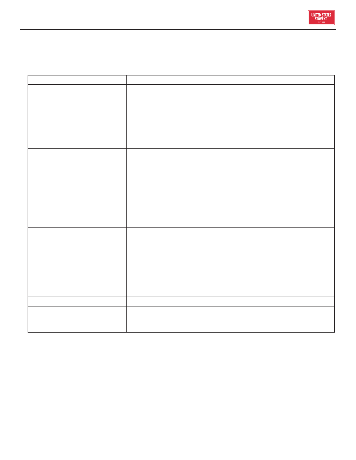
TROUBLESHOOTING GUIDE
PROBLEM CAUSE: Too rich air/fuel mixture
Orange, lazy flame, excessive fuel
build-up in the burnpot.
Clean out the burnpot
Make sure the cleanouts on each side of the damper are closed completely.
Not enough combustion air. Adjust the air damper to a more open position.
Make sure that the viewing door is closed and sealed properly. If not, adjust the
door catch or replace the gasket.
Check that all outside connections are clear of any obstructions.
Check the exhaust system, clean as needed.
PROBLEM Cause: Burnpot out of fuel
Fire goes out or heater shuts down
Hopper is empty, refill the hopper
Loss of draft pressure. Make sure the viewing door is closed and sealed
properly. Check the outside connections for any obstructions. Check the
exhaust system; clean as needed.
Check that the pressure switch connection to the firebox is free of ashes or
clear of any obstructions.
Auger system may be jammed or there is a “bridging” of fuel in the hopper
preventing fuel flow into the auger feed system.
Too much combustion air. Adjust damper to a more closed position.
PROBLEM Cause: Auto-Start Igniter fails to ignite the fuel in the burnpot.
Heater does not start a fire when the
“ON” button is pressed.
Check the pellets quality. If moist or damp, replace with dryer fuel.
Check that the auto-start igniter port is not blocked with ash or soot. (The
igniter is located behind the burnpot.)
The auto-start igniter should glow on start-up. If you can not visible see the
igniter glowing, then it may need to be replaced or there is a problem with the
electrical system. Check wiring.
Loss of draft pressure. Make sure the viewing door is closed and sealed
properly. Check the outside connections for any obstructions. Check the
exhaust system; clean as needed.
PROBLEM Cause: Not enough combustion air or fuel has too much moisture.
Viewing glass becomes black shortly
after start-up.
Adjust the air damper to a more open position.
Use a fuel with less moisture content.
PROBLEM Cause: Not enough combustion air or fuel has too much moisture.
• Disconnect the power supply before performing any maintenance! NOTE: Turning the heater to “OFF” does not
disconnect the power to all of the electrical components of the heater.
• Never try to repair or replace any part of the heater unless instructions for doing so are given in this manual. All other
work should be done by a trained technician.
20
© 2021 United States Stove Company
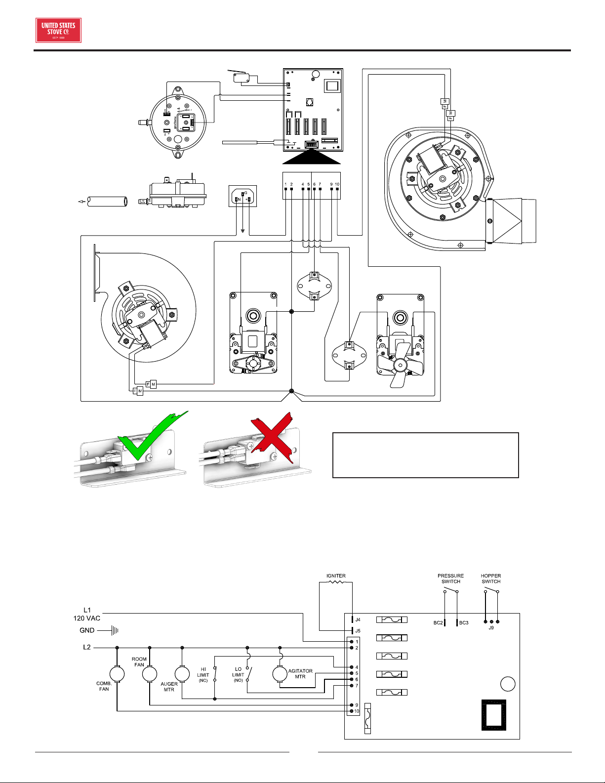
WIRING DIAGRAM
AUGER
MOTOR
BLACK
BLACK
BLACK
BLACK
BLACK
WHITE
RED
BROWN
YELLOW
PURPLE
BLUE
ORANGE
YELLOW
LOW
LIMIT
HIGH
LIMIT
AGITATOR
MOTOR
POWER SUPPLY
MOLEX PLUG TO CIRCUIT BOARD
IGNITER
BLACK
MICROSWITCH
PRESSURE SWITCH
HOSE
To Firebox
BLACK
ROOM FAN
DRAFT FAN
WHITE
WHITE
WHITE
WHITE
WHITE
WIRING SCHEMATIC
CORRECT WRONG
Ensure the wires are connected to
the bottom two prongs of the hopper
switch as shown.
© 2021 United States Stove Company
21
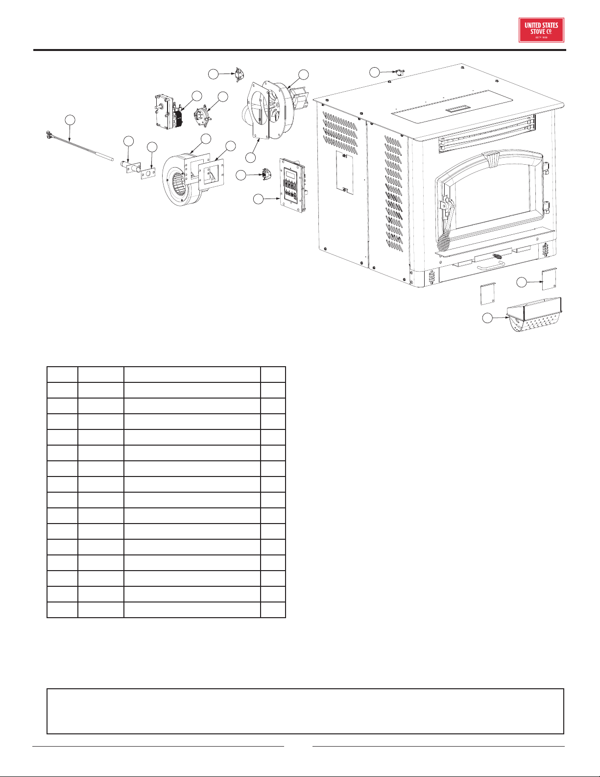
REPAIR PARTS
Key Part # Description Qty
1 80543 Igniter Cartridge 1
2 69593 Igniter Tube Weldment 1
3 88118 Igniter Flange Gasket 1
4 80456 Drive Motor (Agitator) 1
5 80549 Pressure Switch 1
6 80472 Distribution Blower 1
7 88106 Distribution Blower Gasket 1
8 80381 110°F Snap Disc (Low Limit) 1
9 80473 Exhaust Blower 1
10 88100 Exhaust Blower Gasket 1
11 80390 170°F Snap Disc (High Limit) 1
12 80575 PCB, Circuit Board 1
13 80491 Micro Switch 1
14 891660 Burnpot 1
15 25524 Ash Cleanout (Inner) 2
1
2
3
4
5
6
7
8
9
11
12
15
14
13
10
To order parts:
Call 1-800-750-2723 Ext 5051 or
Email to: parts@usstove.com
IN ORDER TO MAINTAIN WARRANTY, COMPONENTS MUST BE REPLACED USING USSC PARTS PURCHASED
THROUGH YOUR DEALER OR DIRECTLY FROM USSC. USE OF THIRD PARTY COMPONENTS WILL VOID THE
WARRANTY.
22
© 2021 United States Stove Company
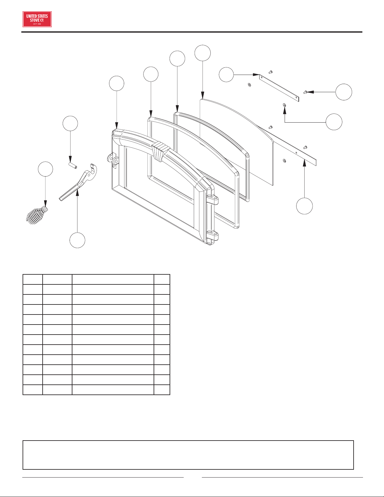
REPAIR PARTS
4
3
1
5
6
7
2
9
8
10
11
Key Part # Description Qty
1 25491 Feed Door 1
2 25492 Handle, Door 1
3 83506 Roll Pin, 3/8 x 1-1/4 1
4 891135 Handle, Spring (Parts Bag) 1
5 88112 Gasket, 1/2” Sq. Rope 5 ft
6 88087 Gasket, Glass (1 x 3/16) 4 ft
7 891131 Glass Ceramic 1
8 25464 Retainer, Top Glass 1
9 25465 Retainer, Bottom Glass 1
10 83202 Machine Screw 4
11 83278 #10 Flat Washer 4
To order parts:
Call 1-800-750-2723 Ext 5051 or
Email to: parts@usstove.com
IN ORDER TO MAINTAIN WARRANTY, COMPONENTS MUST BE REPLACED USING USSC PARTS PURCHASED
THROUGH YOUR DEALER OR DIRECTLY FROM USSC. USE OF THIRD PARTY COMPONENTS WILL VOID THE
WARRANTY.
© 2021 United States Stove Company
23
It is recommended that your heating system is serviced regularly and that the appropriate Service Interval Record is
completed.
SERVICE PROVIDER
Before completing the appropriate Service Record below, please ensure you have carried out the service as described in
the manufacturer’s instructions. Always use the manufacturer's specified spare part when replacement is necessary.
Service 01 Date: ______________________
Engineer Name: ____________________________________
License No.: ________________________________________
Company: __________________________________________
Telephone No.: _____________________________________
Stove Inspected:
Chimney Swept:
Items Replaced: ____________________________________
Service 03 Date: ______________________
Engineer Name: ____________________________________
License No.: ________________________________________
Company: __________________________________________
Telephone No.: _____________________________________
Stove Inspected:
Chimney Swept:
Items Replaced: ____________________________________
Service 05 Date: ______________________
Engineer Name: ____________________________________
License No.: ________________________________________
Company: __________________________________________
Telephone No.: _____________________________________
Stove Inspected:
Chimney Swept:
Items Replaced: ____________________________________
Service 07 Date: ______________________
Engineer Name: ____________________________________
License No.: ________________________________________
Company: __________________________________________
Telephone No.: _____________________________________
Stove Inspected:
Chimney Swept:
Items Replaced: ____________________________________
Service 02 Date: ______________________
Engineer Name: ____________________________________
License No.: ________________________________________
Company: __________________________________________
Telephone No.: _____________________________________
Stove Inspected:
Chimney Swept:
Items Replaced: ____________________________________
Service 04 Date: ______________________
Engineer Name: ____________________________________
License No.: ________________________________________
Company: __________________________________________
Telephone No.: _____________________________________
Stove Inspected:
Chimney Swept:
Items Replaced: ____________________________________
Service 06 Date: ______________________
Engineer Name: ____________________________________
License No.: ________________________________________
Company: __________________________________________
Telephone No.: _____________________________________
Stove Inspected:
Chimney Swept:
Items Replaced: ____________________________________
Service 08 Date: ______________________
Engineer Name: ____________________________________
License No.: ________________________________________
Company: __________________________________________
Telephone No.: _____________________________________
Stove Inspected:
Chimney Swept:
Items Replaced: ____________________________________
SERVICE RECORD
24
© 2021 United States Stove Company
NOTES
