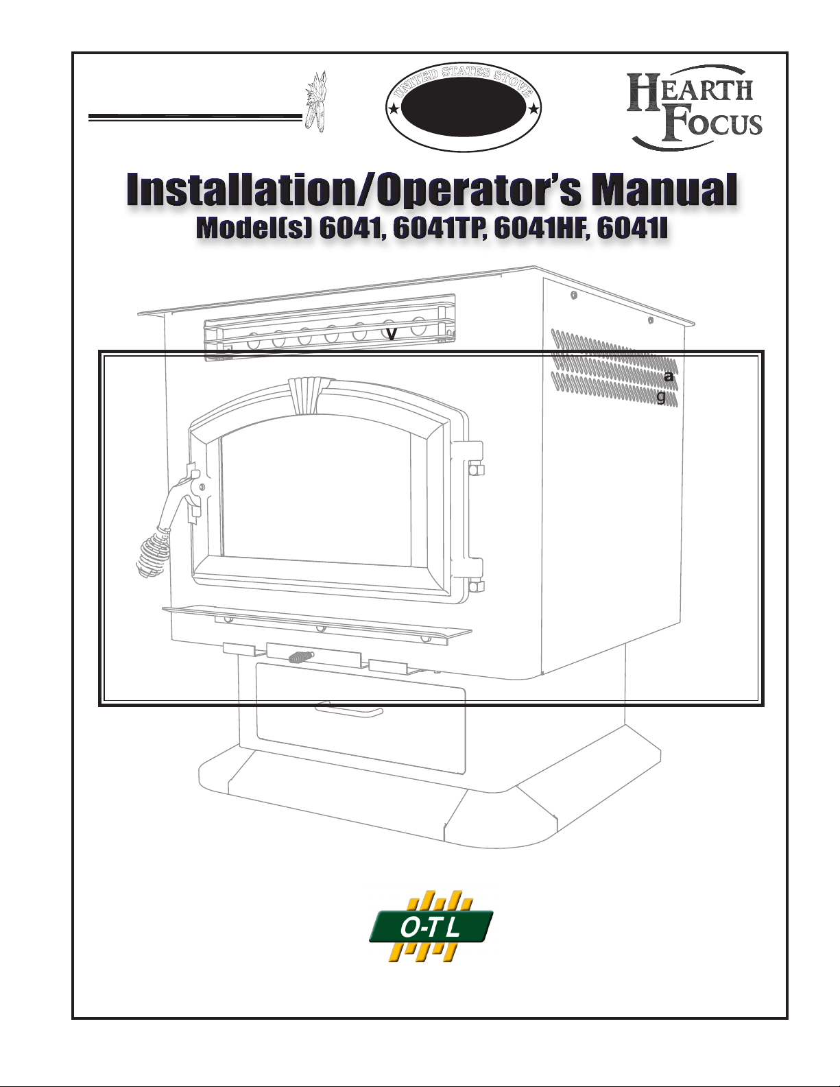
USSC 1
851772 rev A
C
S
S
U
C
O
M
P
A
N
Y
U
N
I
T
E
D
S
T
A
T
E
S
S
T
O
V
E
United States Stove Company • 227 Industrial Park Road, P.O. Box 151 • South Pittsburg, TN 37380 • www.usstove.com
Safety Tested to ASTM-E 1509, (UM) 84-HUD
American Harvest
Safety Notice: If this heater is not properly installed, a house re may result.
For your safety, follow the installation directions. Contact local building or re of-
cials about restrictions and installation requirements peculiar to your area. Do
Not Plug this appliance into an electrical outlet before reading and understanding
all operations and always unplug the unit before attempting any work or main-
tenance. Do not connect this heater to any chimney ue already serving another
appliance. Carefully observe and maintain all clearances to combustibles.
A note about fuel: Use only dried shelled corn with a moisture content of 14%
or less (11 to 12% provides the best results); any pellet fuel used should
have an ash content of 1% or less. If not, efciency will suffer. This heater has
successfully burned pellets with a 2-1/2% ash content, though less ash is preferred
and more efcient.
Your American Harvest Multi-Fuel Heater operates on a negative pressure. There-
fore, all venting connections (elbows, T-pipe) must be sealed and airtight.
i
Use Hi-Temp silicone at each joint or connection.
READ THIS ENTIRE MANUAL, THOROUGHLY, BEFORE ATTEMPTING TO INSTALL AND/
OR BURN YOUR NEW AMERICAN HARVEST *MULTI-FUEL HEATER. FAILURE TO FOLLOW
THESE INSTRUCTIONS MAY RESULT IN PROPERTY DAMAGE, BODILY INJURIES OR
EVEN DEATH.
*This heater is capable of burning wood, biomass pellets and a wide variety of grains,
including corn, soybeans, cherry and olive pits, and all larger seeds.
SAVE THESE INSTRUCTIONS
UNITED STATES STOVE COMPANY GRANTS NO WARRANTY, IMPLIED OR STATED,
FOR THE INSTALLATION OR MAINTENANCE OF THE HEATER AND ASSUMES NO
RESPONSIBILITY FOR ANY CONSEQUENTIAL DAMAGE(S).
Tested &
Listed By
Portland
Oregon USA
Omni-Test Laboratories, Inc.
US
2 USSC
NOTE: YOUR UNIT MUST BE INSTALLED BY A
QUALIFIED INSTALLER, such as an NFI (National
Fireplace Institute) Certied Specialist
You’ve purchased one of America’s Finest Multi-fuel Burning Heaters. By heating
with fuels such as corn and pellets, you’re helping CONSERVE AMERICA’S ENERGY!
We strongly suggest installing smoke detectors in your home if not already installed.
Initial burn off may cause slight smoke and odor the rst few hours of operation.
Perform initial burn outside if possible
SPECIFICATIONS
United States Stove Company reserves the right to alter products, specications and price without
notice.
Safety Tested & Listed to ASTM- E 1509, (UM) 84-HUD, by OMNI Test Laboratories, Inc., Portland,
Oregon USA
BTU output will vary, depending on the brand, type and quality of fuel and the moisture content. Consult your
dealer for best results.
Based on post 1982 home construction, requiring 35 BTU/Hr per Sq. Ft.
Remember, this heater should not be used as the only source of heat in the house.
Power outages and neglect of periodic maintenance will result in a total loss of heat.
Heat Input (as tested) 45,000 BTU/HR
Heat Output
(as tested) 35,100 BTU/HR
Heating Capacity 1,000-2,000 Sq. Ft
Fuel Storage Capacity 60 Lbs.
Width 29 in./737mm
Height 6041TP/6041HF
31 in./787mm
6041I
24 in./610mm
Depth 28 in./711mm
USSC 3
1
1
2
2
A A
B B
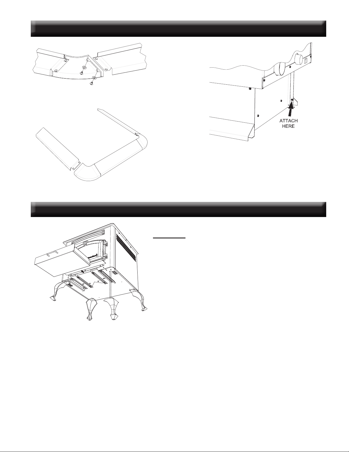
Assembly
1. Unpack unit and make sure all components are included; (4) Legs,
and all hardware for installation.
2. Fold the corner padding from the carton and lay it on the oor behind
the unit. This is used to hold the heater up off the oor to install the
legs. Gently tilt the heater on its back, door opening up.
3. Assemble the legs as shown using the eight(8) 1/4-20 bolts supplied.
4. After all bolts and screws have been tightened properly, carefully
set the heater back up on the legs.
6041HF ASSEMBLY
6041TP PEDESTAL TRIM ASSEMBLY
Assemble trim pieces as shown with the screws
provided in the parts bag.
After trim assembly, attach to the pedestal base at the
location shown using the screws provided.

4 USSC
(a)
(a)
(c)
(h)
(f)
(g)
(b)
(e)
6041I ASSEMBLY
(i)
(j)
For the following assemblies, we suggest locating the unit
near it’s desired location. Depending on installation, you
may want to connect the exhaust venting before installing
the facade parts.
Assembly - Facade (Surround)
Remove contents from packaging and make sure you have
all components:
(2) Top Facade (a)
(1) Left Side Facade (b)
(1) Right Side Facade (c)
(4 pieces)Facade Trim Kit (d)
(1) Feed Door Spring Handle (e)
(1) Damper Spring Handle (f)
(1) Ash Pan “U” shaped Handle (g)
(1) Access Door Knob (h)
(1) PCB Cover (i)
(1) Panel Cover (j)
(1) Auger (in ash pan)
(1) Power Cord
(1) Burnpot Poker (k)
Mounting Hardware
Start by mounting either the left or right side facade pieces to
the unit using four(4) of the supplied #10 x 1/2 screws. Then
put the two(2) top facade pieces together with two(2) of the
#10 x 1/2 screws provided. Attach the top facade assembly
to the unit with eight(8) of the same screws.
Control Board (PCB) Re-location
Remove the left side front panel from the unit. While holding
the PCB with one hand, remove the two(2) hex head screws
holding the board in place. It is not necessary to unplug the
PCB cable. Route the board and cable through the opening
and mount it to the Left Facade using two of the #10 x 1/2
phillips head screws provided. Then attach the PCB cover
to the back of the facade covering the board. Next, use the
two hex head screws removed earlier and mount the cover
panel over the opening where the PCB was located. See il-
lustration to the left.
Facade Trim
Remove trim from shipping tube. There should be one(1)
left side, one(1) right side, two(2) top pieces, and mounting
hardware. Using one blank corner key and one corner key
with set screws, assemble the left trim and one of the top
pieces together. As illustrated, place the blank key behind
the key with the set screws. Adjust corners and tighten set
screws. Repeat this for the right side
Before removing tape, place trim assembly against facade
to get an idea of how it is to be mounted. Remove the strip
from the adhesive and carefully secure the trim in place by
rmly pressing it to the facade.
Burnpot Poker
The burnpot poker may be used several ways. It is used
primarily as a fuel-loading assistant to help push the fuel to
the rear of the hopper for maximum fueling. It may also be
used for cleaning of ashes or removal of clinkers.
DISCONNECT THE POWER CORD BEFORE SERVICING THIS Heater
Flat Pattern
SCALE 1 / 3
1
1
2
2
3
3
4
4
A A
B B
TOLERANCES
EXCEPT
AS
NOTED
HOLES
+
.005" -.001"
DECIMAL
.XX = 0.03 XXX = 0.010
ANGULAR
`
2
~
DESCRIPTION
BLANK NUMBER
REFERENCE
SCALE
DWN BY
DATE
SIZE
REV
TITLE NUMBER
UNITED STATES STOVE COMPANY
ESTABLISHED 1869
POKER, BURNPOT
25589
AB
6039i
12 GA. HRS
CEC
4/18/2007
1:2
52182
1
OF
1
SHEET
REVISION HISTORY
REV DESCRIPTION DATE BY
A INITIAL RELEASE 4/18/2007 CEC
60°
3.00
1.80
1.13
(0.105)
1.80
B.P.
15.26
0.38
0.75
15.76
14.92
(k)
(d)
USSC 5
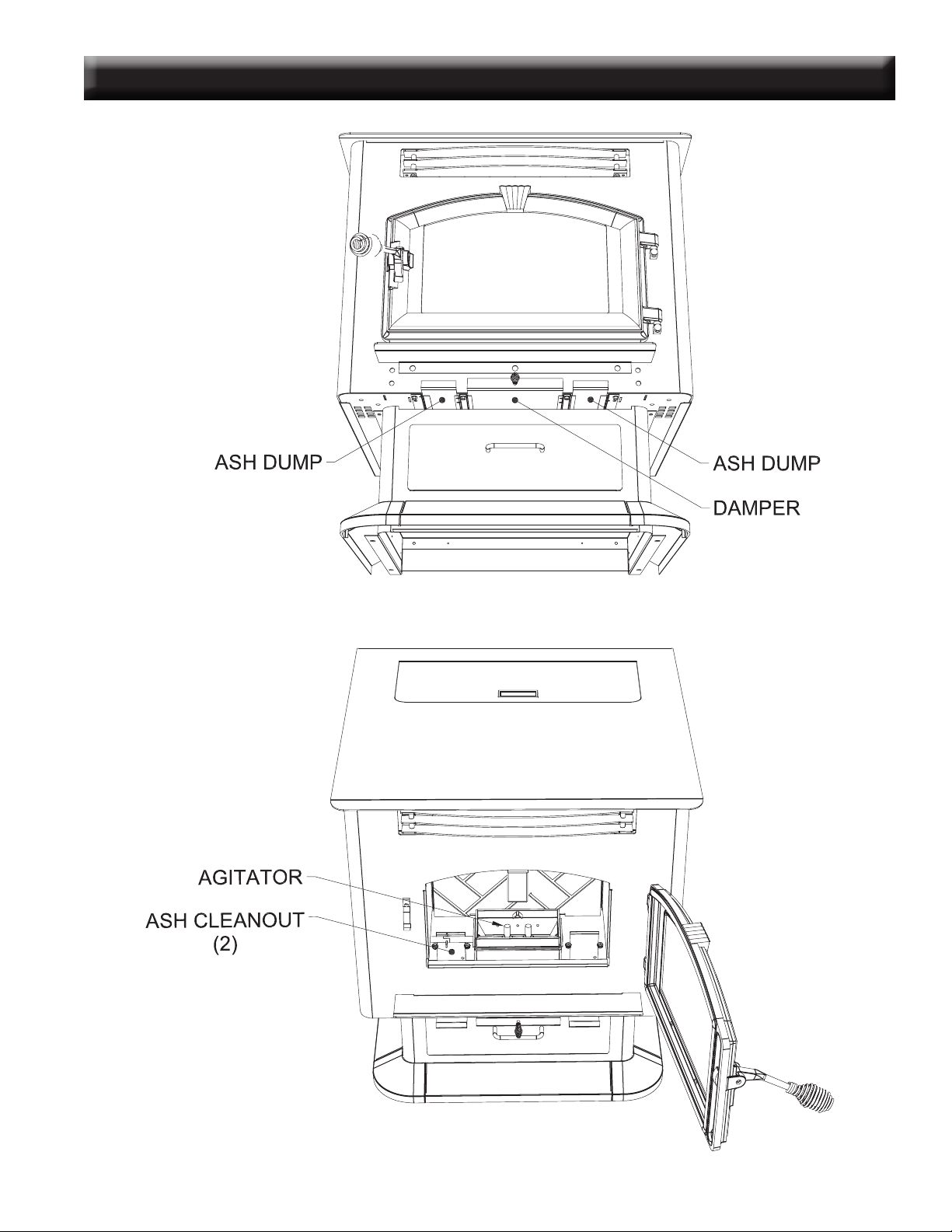
COMPONENT LOCATION

6 USSC
Ashes will have to be removed from the heater for proper operation. See cleaning procedure.
Your Multi-fuel heater, due to the nature of solid fuels, will require brief periodic attention. Please do not expect to light
your heater and walk away from it. A few moments of adjustment and cleaning is an important part of burning solid
fuels, due to the vast differences in fuel, humidity and outside temperature.
The Multi-fuel heater has been designed to burn dry shelled corn, wood pellets and other pelletized fuels that meet As-
sociation of Pellet Fuel Industries standards.
SAFETY STEPS
IMPORTANT: Proper installation of this heater is necessary for safe and efcient operation. In-
stalling this product improperly may result in a house re and personal injury. All applicable building
codes for your location must be followed. In areas where building codes require additional steps to
the installation of this product not included in this manual, the building codes will take precedent
and must be followed. Contact your local building inspector to obtain any necessary permits or
inspection guidelines before installing the product.
• The American Harvest heater is designed to burn dry shelled corn, cherry pits, or pelletized fuel such as
wood and biomass pellets. The burning of other solid fuels such as cord wood or wood chips in this heater
is not permitted.
• This product requires simple periodic maintenance for proper operation and long life of the heater. Read
and follow the maintenance schedule closely.
• DISCONNECT THE POWER CORD BEFORE SERVICING THIS HEATER!
• A power surge protector is required. The unit must be plugged into a grounded 110-volt power
source. Circuit Boards are very expensive - protect yours!
• Always route the power cord away from the unit. Do not route cord in foot trafc areas. Do not pinch cord
under furniture. Do not route the cord across the exhaust pipe.
• A working smoke detector must be installed in the same room as this product.
• Flammable or explosive liquids such as gasoline, naphtha, alcohol, lighter uid, or engine oil must NEVER
be used in or around this heater. These liquids must be stored well away from this heater as the open
ame in the burner chamber could ignite the fumes of such liquids. Do not burn garbage in this unit.
• The moving parts of this heater are propelled by high torque electric motors. The Auger and Fuel Agitator
can cause severe injury to body parts that may get near them. Keep all body parts away from the Auger
and Fuel Agitator while the heater is plugged into an electrical outlet. These moving parts may begin to
move at any time while the heater is plugged in.
• According to HUD requirements, when installed in a mobile home, this heater must be grounded directly
to the steel chassis of the mobile home and bolted to the oor. Direct air access must be provided - Use
69FAK Fresh Air Kit
• This heater is not intended for use in commercial installations.
• Do not connect this heater to “B” vent. Use UL Listed Pell Vent ONLY!
• Do not elevate the re by use of grate or any other means other than the supplied burnpot.
BURNING SOLID FUELS

USSC 7
FLOOR PROTECTION
The Multifuel Heater may be installed on a combustible oor, with proper oor protection, or on a masonry hearth.
The hearth or noncombustible oor protector must extend a minimum of (6) inches (152mm)in front and (6) inches
(152mm) from each side of the unit.
INSTALLATION REQUIREMENTS
SHELLED CORN (Dry, preferably corn with 11- 12% moisture content)
• Corn must contain less than 14% moisture content. Wet corn will rapidly deteriorate heater components,
reduce efciency and void all warranties. Purchase a moisture tester if in doubt.
• Corn must be clean and free from debris. Never burn corn right from the eld. Damage caused by dirty corn is not
covered by the product warranty. Ask for clean ltered bagged corn only. Stalk parts, excessive nes and cob rem-
nants will clog the auger. Check your corn for foreign objects.
• NEVER BURN SEED CORN IN YOUR Heater. Seed corn is treated with chemical pesticides that are harmful or
fatal if swallowed, therefore, seed corn is dangerous to have in the house, especially where children can reach it.
• Never burn “Deer Corn.” It frequently contains molasses, sugars and salts.
• Store your corn supply in a dry place and keep bags or container sealed to prevent your corn from absorbing excess
moisture. Test the moisture content periodically to ensure the proper dryness.
• There are many varieties of corn grown around the world. Each variety has unique characteristics including the shape
and size of the kernel. Your heater will burn more consistently with a small to midsize kernel corn. If the kernel size
of the corn varies greatly or if you switch sources frequently, you will get a less consistent burn. Therefore, purchas-
ing corn from the same source will help achieve a more consistent burn. DO NOT USE CORN WITH A HIGH WAX
CONTENT!
WOOD and BIOMASS PELLETS
• As with corn, be consistent in your pellet supplier. Pellets will vary in content and burn characteristics from supplier
to supplier. A consistent supply of pellets will result in a more consistent and efcient burn.
• Check your pellets for foreign objects. Your heater warranty will not cover damage done to your heater due to foreign
objects in the fuel supply.
• Store your pellets in a dry place to prevent them from absorbing added moisture.
• To decrease sawdust buildup, the hopper and auger tube will need to be vacuumed out after every 6-8 bags of pellets
or more often if the pellets are poor quality. The hopper should be empty of fuel when this is performed. You may
have to screen each bag of pellets if sawdust becomes a problem.
• Wood Pellets vary in size and ash content from less than 1% to 3% or more. Your heater will burn more efciently
with small to midsize pellets (Preferred pellet size is 1/4” diameter x 1” length). Low ash content pellets will allow
you to burn the heater longer between cleanings. Only wood pellets manufactured to the Pellet Fuel Institute (P.F.I)
standard for residential pellets fuels are recommended. Performance will suffer if nonstandard pellets are used. Consult
your local American Harvest dealer for more information on approved wood pellet fuel.
CAUTION:
DO NOT PLACE SUCH FUELS WITHIN THE SPACE HEATER’S
INSTALLATION CLEARANCES OR WITHIN THE SPACE REQUIRED FOR FUELING AND
ASH REMOVAL.
BURNING SOLID FUELS continued...
8 USSC
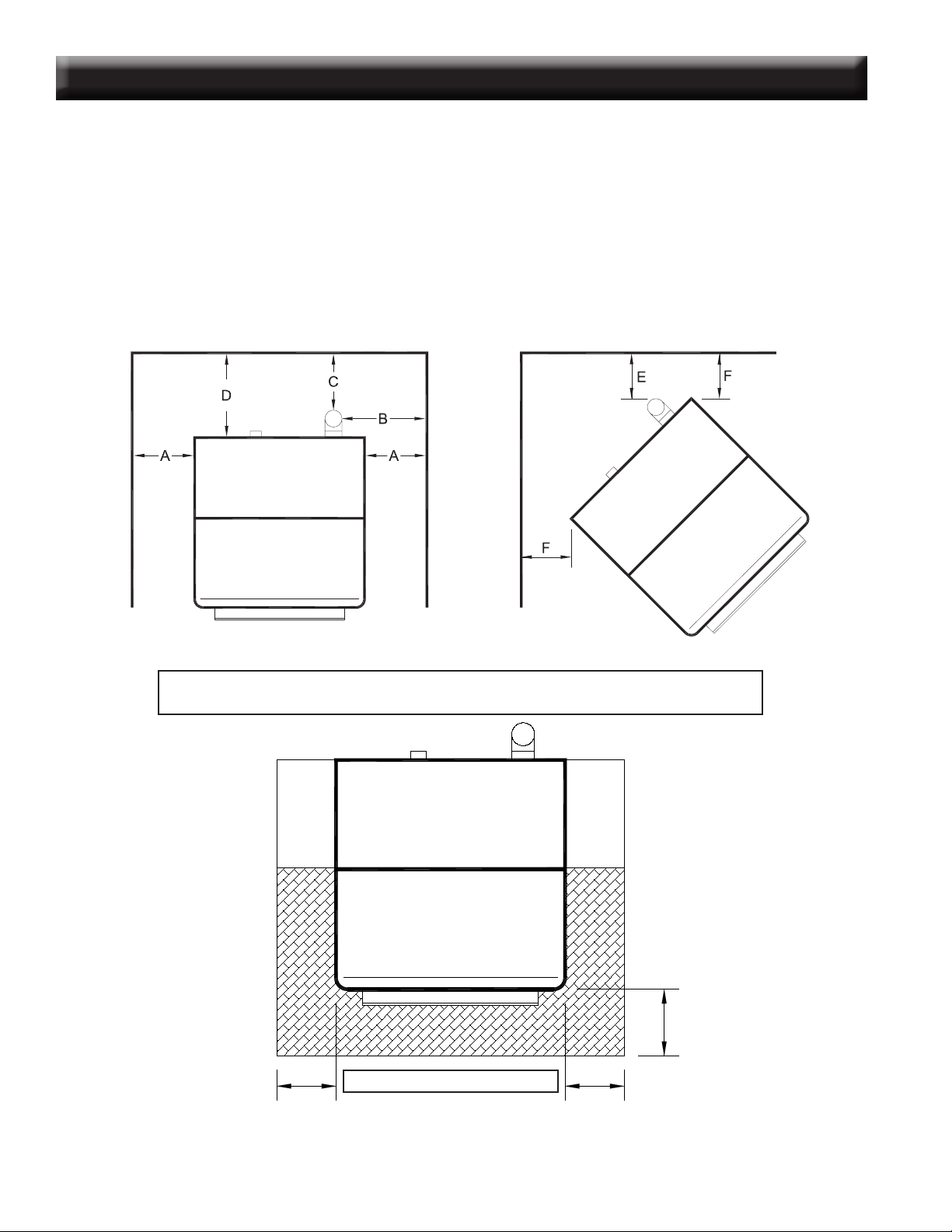
CLEARANCES TO COMBUSTIBLES 6041(TP)(HF)
The heater must be installed with the following minimum clearances to side and back wall combustible materials.
NOTE: These are minimum clearances to combustible walls established by the testing lab.
PARALLEL - A - Sidewall to Top Edge of Unit 8 in./203mm
B - Sidewall to Flue 13 in./330mm
C - Backwall to Flue 3 in./75mm
D - Backwall to Unit 9 in./228mm
CORNER - E - Adjacent Wall to Flue 3 in./75mm
F - Adjacent Wall to Unit 4 in./100mm
BACK WALL
SIDE WALL
SIDE WALL
Backwall / Sidewall
Parallel
BACK WALL
Corner Installation
NOTE:
Allow sufcient space to remove the left and right side panels for maintenance purposes.
6”
min.
HEARTH PROTECTION
These clearances must be maintained.
6”
min.
6”
min.
USSC 9
CLEARANCES TO COMBUSTIBLES 6041I
10 USSC
GUIDELINES FOR EXHAUST VENTING SYSTEMS DESIGN
It is recommended that only an authorized installer install your multi-fuel heater, preferably an NFI certied specialist.
The following installation guidelines must be followed to ensure conformity with both the safety listing of this heater and to local
building codes.
INSTALL VENT AT CLEARANCES SPECIFIED BY THE VENT MANUFACTURER.
• A UL listed 3” or 4” type “PL” pellet vent exhaust system must be used for installation and attached to the pipe connector provided
on the back of the heater. Use a 3” to 4” adapter for 4” pipe. A cap must be used at the termination of type “L” vent chimneys.
4” PL is required for elevations above 2,500 feet above sea level.
• Do not terminate vent in any enclosed or semi-enclosed area, such as; carports, garage, attic, crawl space, under a sundeck or porch,
narrow walkway or close area, or any location that can build up a concentration of fumes such as a stairwell, covered breezeway
etc.
• Vent surfaces can get hot enough to cause burns if touched by children. Noncombustible shielding or guards may be required.
• Do not install a ue damper in the exhaust vent of this unit.
• Termination must exhaust above air inlet elevation. Installation MUST include three (3) vertical feet of pellet vent pipe. This will
create some natural draft to prevent the possibility of smoke or odor during appliance shutdown and to keep exhaust from caus-
ing a nuisance or hazard from exposing people or shrubs to high temperatures. Do not connect this unit to a chimney ue
serving another appliance. Do not connect directly to a masonry chimney.
• The installation must include a cleanout tee to enable collection of y ash and to permit periodic cleaning of the exhaust system.
90
°
elbows accumulate y ash and soot thereby reducing exhaust ow and performance of the heater. Each elbow or tee reduces
draft potential by 30% to 50%. Use no more than 180 degrees of elbows (two 90-degree elbows, or two 45-degree and one
90-degree elbow, etc.) and one cleanout tee to maintain adequate draft. Cleanout tees and elbows should not be connected to
the rear of the unit unless a 3-inch adapter is used.
• Total length of horizontal vent must not exceed 48”(4ft.)/1,200mm. The maximum recommended vertical venting height is 12-feet
for 3-inch type “PL” vent. For venting higher than 12-feet, 4-inch “PL” vent must be used. All joints in the vent system must be
fastened by at least 3 screws, and all joints must be sealed with RTV silicone sealer to be airtight.
• The area where the vent pipe penetrates to the exterior of the home must be sealed with silicone or other means to maintain the
vapor barrier between the exterior and the interior of the home.
NOTE: These are guidelines only. Proper venting is accomplished by design and necessary requirements. In
most installations 3 inch diameter venting is adequate. If it does not vent properly you will have to change it to 4
inches. You should not exceed 4 inch diameter venting.
DO NOT CONNECT TO ANY AIR DISTRIBUTION DUCT OR SYSTEM
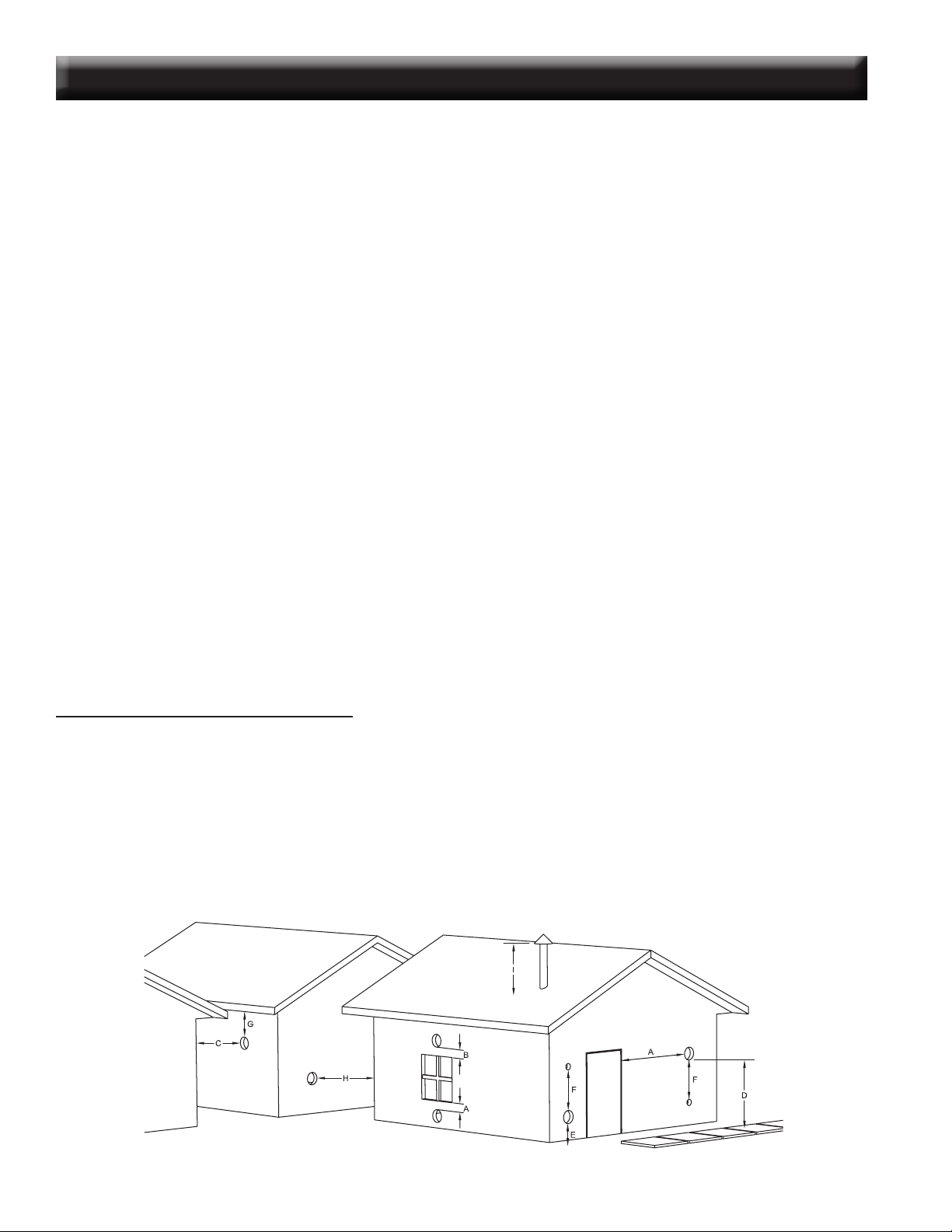
VENT TERMINATION CLEARANCES:
A) Min. 4-ft clearance below or beside any door or window that opens.
B) Min. 1-ft clearance above any door or window that opens.
C) Min. 3-ft clearance from any adjacent building.
D) Min. 7-ft clearance from any grade when adjacent to public walkways.
E) Min. 2-ft clearance above any grass, plants, or other combustible materials.
F) Min. 3-ft clearance from a forced air intake of any appliance.
G) Min. 2-ft clearance below eaves or overhang.
H) Min. 1-ft clearance horizontally from combustible wall.
I) Must be a minimum of 36-inches above the roof and 24-inches above the highest point or the roof within 10-feet.
USSC 11
1. For installations with horizontal through-the-wall exhaust, it is strongly recommended that the heater combustion
air be connected to the outside. If the home is newer or has been tightly insulated, it is required to install outside
combustion air.
2. Connection to outside the house is REQUIRED for mobile home installations. We strongly urge use of the 69FAK
Fresh Air Kit.
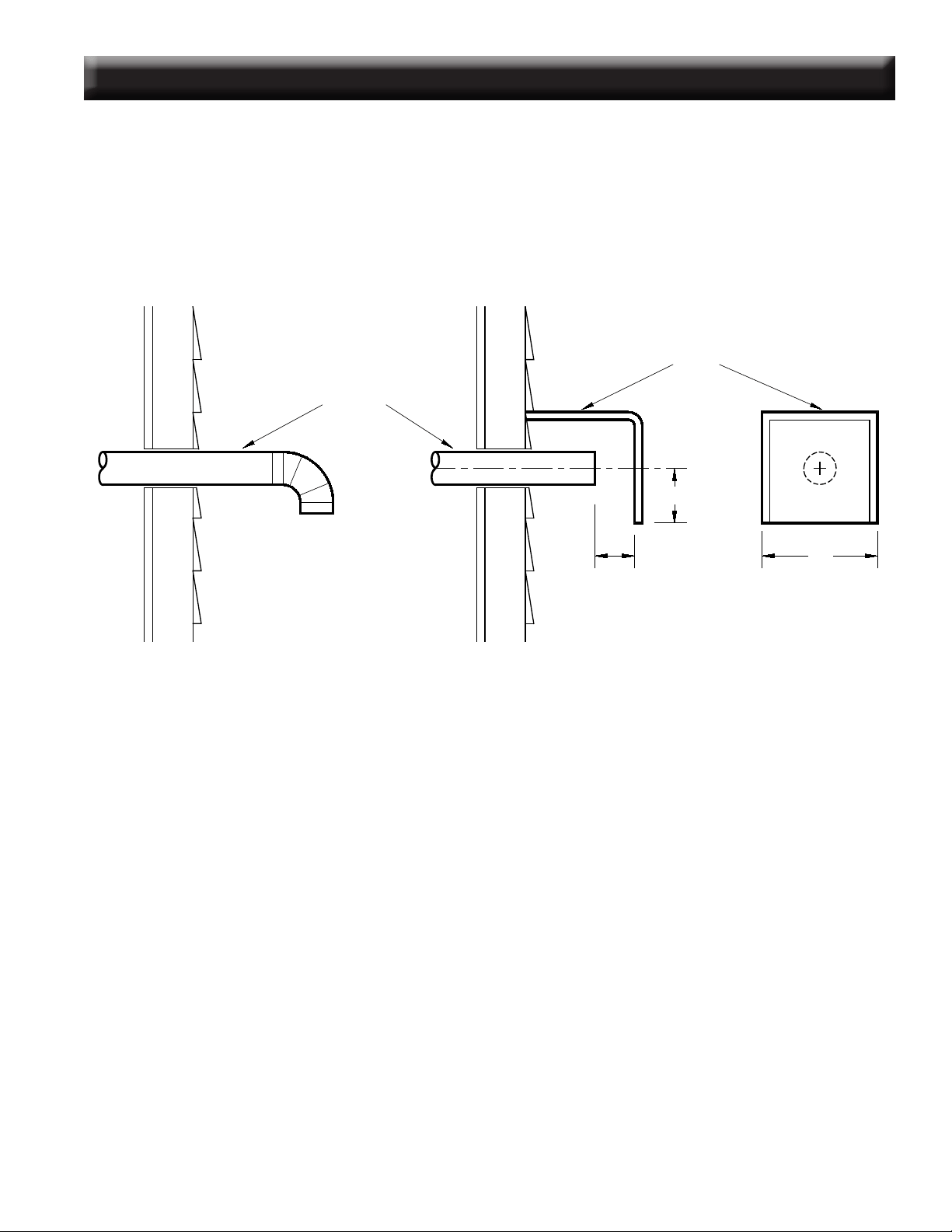
90 DEGREE BEND TERMINATION WIND HOOD TERMINATION
2” Min. Diameter
Wind Hood
2”
3”
6”
NOTE:
A wire mesh screen with a maximum
opening size of 3/8” must be
installed in the pipe or elbow for
rodent exclusion.
DESIGN GUIDELINES FOR OUTSIDE COMBUSTION AIR CONNECTION
3. Only noncombustible pipe 2 inches (or greater) in diameter is approved to use for outside air connections (straight
or exible). PVC pipe is NOT approved and should NEVER be used.
4. If the air inlet is connected to the outside, it MUST be terminated with a vertical 90-degree bend (down) or with a
wind hood. Failure to do so could result in a burn back during high winds blowing directly up the air inlet during a
simultaneous power failure (see diagram above).
5. Blockage, excessive length, or extra bends in the air intake pipe will starve the heater of combustion air. A 90-degree
bend is equivalent in restriction to approximately 30 inches of straight inlet pipe.
CAUTION: The operation of exhaust fans such as bath room fans, attic fans, etc. might starve the heater of combus-
tible air creating a negative pressure in the room. Provide adequate ventilation in the room accompanying the heater.
If not, the pressure switch may shut off operation of the heater. (Due to negative pressure)
12 USSC
The
Multifuel Heater Model 6041TP/6041HF may be installed as
follows:
1) A freestanding unit
The
Multifuel Heater Model 6041I insert may be installed as
follows:
1) In a pre-fab rebox (Factory Built)
2) In an existing masonry replace
3) As a build-in
MOBILE HOME INSTALLATION REQUIREMENTS
IN ADDITION TO THE STANDARD INSTALLATION INSTRUCTION, THE FOLLOWING
REQUIREMENTS ARE MANDATORY FOR INSTALLATION IN A MOBILE HOME:
WARNING
DO NOT INSTALL IN SLEEPING ROOM
CAUTION
THE STRUCTURAL INTEGRITY OF THE MOBILE HOME FLOOR, WALL AND CEILING/
ROOF MUST BE MAINTAINED.
Check with your local building ofcial as other codes may apply.
INSTALLATION CONFIGURATIONS
1) Heater must be permanently bolted to the oor. Remove the Base Trim and bolt thru the base ange.
2) Heater must have permanent outside air source. (69FAK)
3) Heater must be permanently electrically grounded to the steel chassis of the mobile home.
4) All vertical chimney vent must have wall supports.
5) All exhaust systems must have a spark arrestor.
USSC 13
1
1
2
2
3
3
4
4
A A
B B
12 1/8
11 3/4
10 1/16
EXHAUST OULET
3" DIA.
COMBUSTION
AIR INTAKE
1 7/8" DIA.
10 1/16
11 5/8
12
EXHAUST OUTLET
3' DIA
COMBUSTION
AIR INTAKE
1 7/8" DIA
3" PL Vent (12" Long)
Inner Wall Thimble
Outer Wall Thimble
3" PL Vent (12" Long)
3" PL Tee w/ Cleanout
3" PL Vent (12" Long)
3" PL Vent 90° Elbow
3" PL Vent Termination Cap
Note: Always check dimensions on unit before cutting hole in wall
1
1
2
2
3
3
4
4
A A
B B
12 1/8
11 3/4
10 1/16
EXHAUST OULET
3" DIA.
COMBUSTION
AIR INTAKE
1 7/8" DIA.
10 1/16
11 5/8
12
EXHAUST OUTLET
3' DIA
COMBUSTION
AIR INTAKE
1 7/8" DIA
1
1
2
2
3
3
4
4
A A
B B
12 1/8
11 3/4
10 1/16
EXHAUST OULET
3" DIA.
COMBUSTION
AIR INTAKE
1 7/8" DIA.
10 1/16
11 5/8
12
EXHAUST OUTLET
3' DIA
COMBUSTION
AIR INTAKE
1 7/8" DIA
6041TP - PEDESTAL UNIT 6041HF- LEG UNIT
Dimensional tolerance
±1/4”
*For illustrations purposes only
A MINIMUM OF 3 VERTICAL
FEET OF PIPE OUTSIDE THE
HOME IS REQUIRED!
14 USSC
THROUGH THE WALL, VERTICAL PIPE INSTALLATION
WITH TERMINATION CAP
The Hearth Pad is not required under the unit if the oor is noncombustible but is required 6 inches (152mm) beyond
the front of the unit and 6 inches (152mm) beyond each side of the door if the oor is a combustible oor. (wood oor-
ing, carpet, linoleum, etc.)
A MINIMUM OF 3 VERTICAL
FEET OF PIPE OUTSIDE
THE HOME IS REQUIRED!
USSC 15
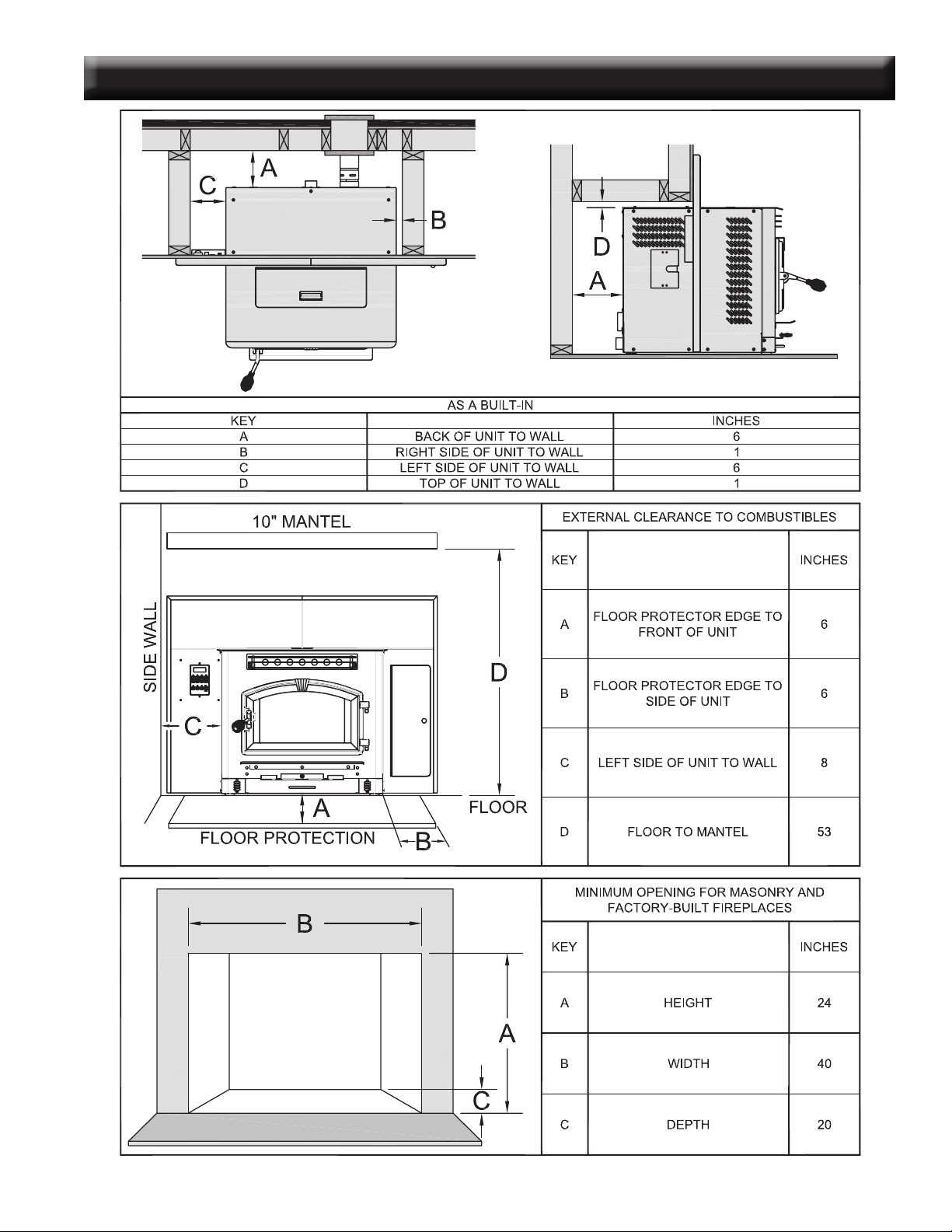
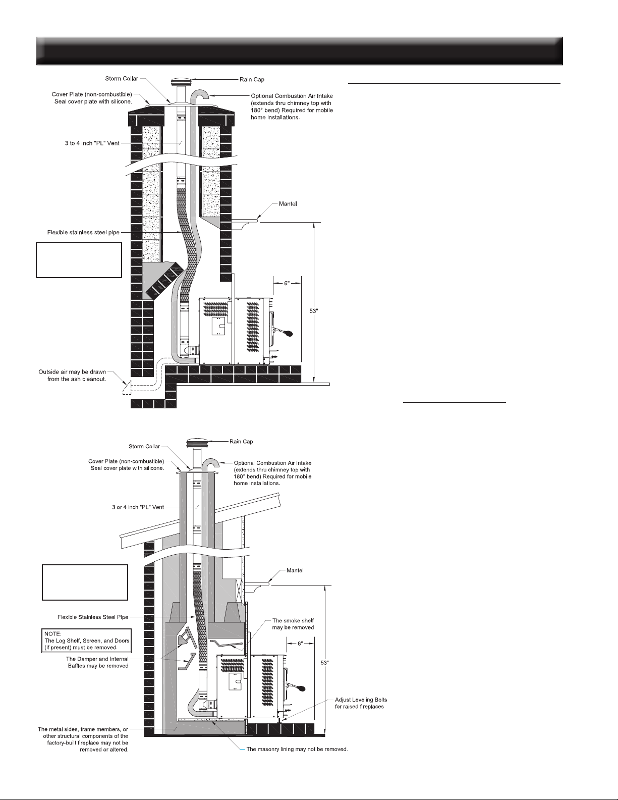
DESIGN GUIDELINES FOR 6041I INSERT INSTALLATION
INSTALLATION AS A BUILT-IN FIREPLACE
A continuous sheet of non-combustible oor protection must be installed underneath the unit to prevent the possibil-
ity of embers falling through to the combustible oor. If the oor beneath the unit is of non-combustible material, the
protector is not required.
See the “Clearance to Combustibles” section of this manual for installation clearances.
Alternative Exhaust Venting
Depending on your installation, you might consider routing your cleanout
tee as illustrated below for ease of cleaning. The access panel in the right
side facade allows you to reach the tee from the front side of the unit if
venting is assembled as shown. The cleanout tee is attached to a 90°
elbow mounted to the unit then rotated at approx. 15-20 degrees. A 12
inch section of “PL” vent is connected to reach the top of the unit to which
a exible pipe may be attached for further termination through a chimney.
Clearance to combustibles must be considered if this installation is chosen.
A distance of 3 inches must be maintained from the exhaust vent to any
combustible material.
A MINIMUM OF 3 VERTICAL
FEET OF PIPE OUTSIDE THE
HOME IS REQUIRED!
16 USSC
DESIGN GUIDELINES FOR 6041I INSERT INSTALLATION
INSTALLATION INTO A MASONRY FIREPLACE
When installing into a masonry replace, DO NOT
remove any bricks or masonry, with the following
exception: masonry or steel, including the damper
plate, may be removed from the smoke shelf and
adjacent damper frame, if necessary, to accommo-
date a chimney liner. Do this only if their removal
will not weaken the structure of the replace or
the chimney, and will not reduce protection for
combustibles to less than that required by national
building codes.
Installation must include a chimney liner (4” Pell
Vent “PL” Piping) that extends the full height of the
chimney and meets type HT requirements. The
liner must be securely attached to the insert and
the chimney top. The chimney must be sealed
either at the top or at the damper area with a non-
combustible plate to prevent room air passage to
chimney cavity.
Outside combustion air may be drawn through the
chimney top or through an existing ash cleanout.
INSTALLATION INTO A FACTORY-BUILT
(METAL) FIREPLACE
When installing into a zero clearance replace, The
rebox must accept the insert without modication
other than removing bolted or screwed together
pieces such as smoke shelf/deectors, ash lips,
screen or door tracks, and damper assemblies.
These items must be re-installed if the insert is
removed and not replaced. The removal of any
part must not alter the integrity of the listed re-
place in any way.
The factory built replace must be listed per UL
127. Installation must include a chimney liner (4”
Pell Vent “PL” Piping) that extends the full height
of the chimney and meets type HT requirements.
The liner must be securely attached to the insert
and the chimney top. The chimney must be sealed
either at the top or at the damper area with a non-
combustible plate to prevent room air passage to
chimney cavity.
For raised hearth installations, adjust the leveling
bolts under the front of the unit.
4” VENT IS MANDA-
TORY FOR INSERT
INSTALLATIONS.
4” VENT IS MANDA-
TORY FOR INSERT
INSTALLATIONS.
USSC 17
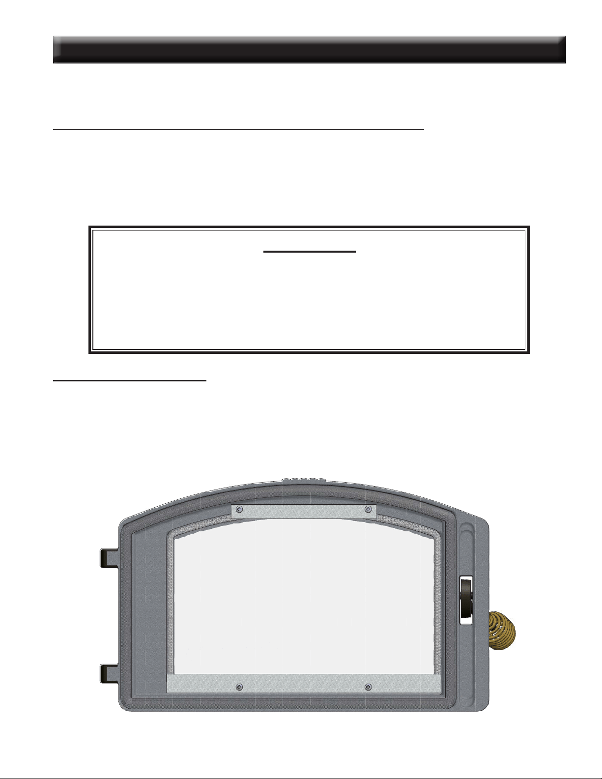
Your
Multi-Fuel
Heater comes to you with the glass door installed in place, ready for use. The glass is surrounded
on the edges with a gasket and seated in a glass channel. It is held in place with two (2) clips.
REMOVAL OF BROKEN OR DAMAGED CERAMIC GLASS
Open the door and then lift it off of the hinges. If the door is tight, tap gently on the bottom of the door with your hand
or rubber hammer. Lay door down on newspaper with glass clips facing you. Using a #2 Phillips screwdriver, loosen the
screws and take off the glass clips. Remove the broken glass carefully and discard.
Reverse the above procedure for replacing new glass with new gasket. Do not over tighten the screws. Over tighten-
ing can cause the glass to break.
WARNING
Do not operate unit with broken glass.
Do not substitute original factory glass.
You must use only factory authorized glass;
Do not slam door shut.
Do not strike glass.
Do not use abrasive cleaners.
CLEANING THE GLASS
When the re is rst started, it will produce some smoke. The soot might accumulate on the glass surface. Before the
glass surface gets hot, open the door and wipe the glass surface off with a rag. Do not touch the surface with your
hands. If after constant use, the glass is dirty, you must clean the glass so that it will not become etched with the y
ash. When the glass has cooled off, take a damp rag and clean with Hearth Glass Cleaner available from your dealer.
Do not use a rag that contains nylon because it will melt to the glass.
GLASS MAINTENANCE, REMOVAL AND REPLACEMENT
1
1
2
2
3
3
4
4
A A
B B
GLASS CLIPS
.
-
18 USSC
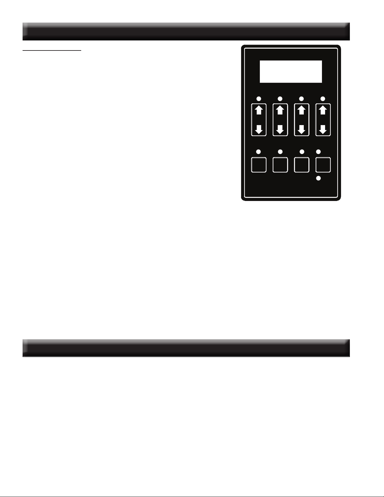
UNDERSTANDING THE CONTROL BOARD
CONTROL PANEL
Turning the heater OFF/ON, as well as adjustments for the fuel feed rate and room
fan speed are performed by pressing the appropriate button(s) on the control panel
which is located on the lower left-hand side of your American Harvest heater. The
insert model 6041I is located on the left facade.
This unit has two fuel operation modes for different fuels, corn or pellet. It may also
be changed between an automatic operation or a manual operation in either of the
fuel modes. The heater comes from the factory in the corn mode.
Pressing the “ON” button on the control panel will begin the start-up sequence for the
heater. The start-up sequence differs depending on which fuel operation mode you
select. See Lighting Instructions for details. Pressing and holding the “ON” button
will rotate the auger continuously until button is released, which feeds additional fuel.
Pressing the “OFF” button on the control panel will cause the heater to enter its shut-
down sequence. The fuel feed system will stop pulling fuel from the hopper and, once
the re goes out and the heater cools down, the fans will stop running.
Pressing the “Heat Range” arrows, up or down, will adjust the amount of fuel being
delivered to the burnpot.
The draft fan (exhaust) will come on as soon as the “ON” button is pressed. The fan
will automatically adjust its speed in accordance
to the heat range setting. However,
this speed can be manually
operated by pressing the “Draft Fan” arrows up or down.
“Draft Fan” when pressed, the display will show “Df-A”, which is automatic. Press
the arrows again to adjust fan speed. When adjusting the Draft Fan setting, try only
1 setting above or below the heat setting. It is better to leave the heater in the automatic mode and adjust the manual draft slide
to control the combustion air.
The room fan will come on once the unit has reached operating temperature (approx. 110°F). By pressing the “Room Fan” buttons,
the display will show “Rf-A” which is automatic or “Rf-1” through “Rf-9” for manual settings. In auto mode, the room fan’s speed
will automatically be adjusted in accordance with the heat range setting. By pressing the “Room Fan” up arrow, you can adjust
the fan speed setting up to “Rf-9”. The fan speed can be adjusted to a higher setting than the heat setting but not lower than the
corresponding heat range.
The “Aux” button is for Agitator operation. When the unit is “OFF” and the heater is cool, pressing the “Aux” arrows will rotate the
agitator for easy removal for cleaning. The agitator, when in Automatic mode, will operate at set intervals. However, these can be
changed by pressing the arrows on the “Aux” button. The agitator can be adjusted from 0 to 9, setting “0” is off and setting “9” is high.
The “Auger Delay” button can be used to pause rotation of the Auger and Agitator for approx. 1 minute. This can be cancelled by
pressing the “ON” button. The “Auger Delay” is normally used only during the start up cycle to slow the fuel delivery down during
the initial ignition.
The “Mode” button is used to switch between manual and automatic mode. When in auto mode, the fan, auger, and agitator will
operate at preset intervals unless changed manually using the buttons mentioned above. When in manual mode, the draft fan
(exhaust) will operate at full speed (100%), so the air must be controlled with the manual slide damper just below the viewing door.
When the heater is in the manual mode, the optional thermostat will not properly control the unit.
During normal operation, the unit is constantly monitored for problems. In the event of an error condition, the unit will stop and an
error will be displayed. See the list of error codes found at the end of this manual.
ON OFF
Auger
Delay
Mode
Auto
Manual
Heat
Range
Room
Fan
Draft
Fan
Aux.
LIGHTING INSTRUCTIONS
CAUTION: DO NOT USE CHEMICALS OR FLUIDS TO START THE FIRE.
HOT WHILE IN OPERATION. KEEP CHILDREN, CLOTHING AND FURNITURE AWAY.
CONTACT MAY CAUSE SKIN BURNS.
Before lighting your heater for the rst time, make sure that all items are out of the hopper, ash pan and rebox area.
Close all doors and lids. Choose which fuel setting that you wish to operate in, Corn or Pellet. Do this by rst pressing the “ON” button,
then press the “Heat Range” Up and Down arrows together for approximately 3-4 seconds and release. A “C” or “P” in the rst digit
of the display will indicate the mode. The ON LED will be blinking and the display will show “Cr-1” or “Pr-1”, depending on the mode.
The “Heat Range” indicator LED and the “Auto” LED should be lit and the dash in the Heat Range display should be ashing. You will
notice the draft fan starts immediately. If you press the “Heat Setting” button up, the draft fan changes speed, increasing speed the
higher the heat setting. You should begin to see the igniter, located in the center and behind the burnpot, begin to glow after a short
period of time. In Corn Mode, the auger and agitator will start rotating after a few minutes, allowing for proper fuel ignition. In Pellet
Mode, the auger will turn immediately, then the agitator will begin to rotate once the heater reaches operating temperature. Note:
The room fan will not operate at this time, as a temperature of at least 110 degrees must be reached before operating. If proper
operation of your heater is conrmed, press the “OFF” button, then ll your hopper with the desired fuel. Ensure there is no foreign
matter in your fuel, hopper or burnpot. You are now ready to light your Multi-Fuel Heater.
USSC 19
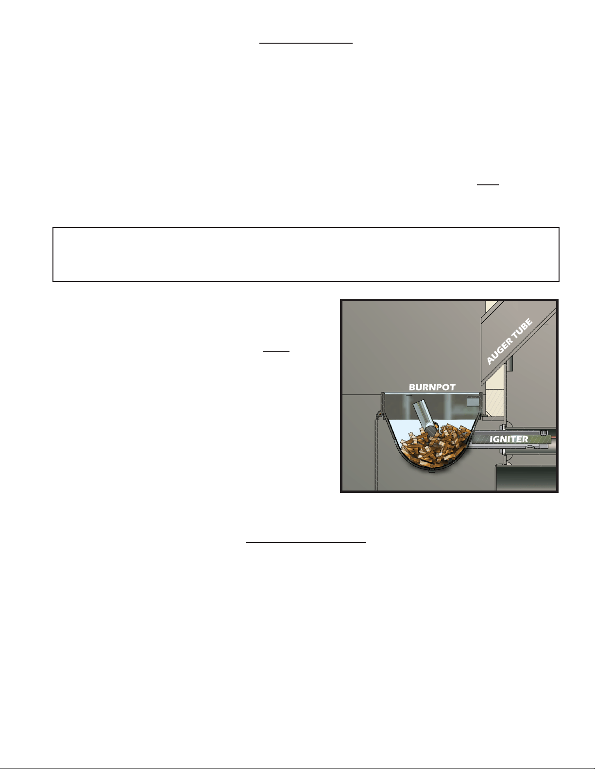
• Fill the burnpot with wood pellets up to the level of the igniter port; See illustration.
• Close all doors, lids, and cleanouts.
• Press the “ON” button and select desired heat range. This will start the
ignition sequence.
Once the wood fuel is ignited and the heater senses heat, the auger and
agitator will begin to rotate, feeding fuel to the burnpot. NOTE: If the start-
ing fuel is not burning hot enough, you may see the re begin to go out as
new fuel is being added. If this occurs, pressing the “Auger Delay” button
will allow the auger to pause for 1 minute. Pressing the “ON” button will
resume the auger if 1 min. is too long. If not enough fuel is the reason
for not burning, pressing and holding the “ON” button will allow the auger
to continuously deliver fuel until you release the button.
• Continue to observe the re until most of the wood pellets have been
consumed and only corn or your selected fuel is burning aggressively.
• Make ne adjustments to the air/fuel with the damper located centered,
under the hearth. You should pull the damper out approximately 1 inch.
It may need to be pulled out more or less depending on your selected
heat setting and fuel quality. Try opening or closing by a 1/4 inch at a
time.
• Once the heater reaches warm temperature, the room fan will start to circulate air into the room.
• Overre Protection - If the heater is being overred, burned too hot, the heater will automatically shutdown to avoid damage
to components in the heater. Refer to “Lighting Instructions” for proper use.
TURNING THE HEATER OFF
Pressing the OFF button will cause the heater to enter a shutdown mode. If the heater has reached operating temperature, the
OFF Indicator will blink until the shutdown procedure succeeds in lowering the heater temperature. The Room Fan will stay on to
cool the heater, and the Exhaust Fan will stay on to remove smoke and heat from the combustion chamber. The Agitator will rotate
continuously until shutdown is complete. The Auger will bump the fuel out every few seconds to prevent the fuel in the auger from
burning. Once the temperature of the burn chamber falls below approximately 90 degrees Fahrenheit and the pressure switch detects
that the door is closed, the fans will stop and the Auger will run for a few seconds to purge the auger system of any burned fuel. At
this point, the OFF Indicator will go out and the heater will turn completely off. If during burning, the heater reached at least 120
degrees Fahrenheit, the shutdown procedure will include a 15 minute shutdown cycle that will keep the heater in the shutdown state
for at least 15 minutes regardless of whether it is cool or pressure is detected. The 15 minute cycle can be turned off by pressing
the off button during shutdown. This will cause the system to exit shutdown and return to the “OFF” mode as soon as the door is
closed and the heater is cool.
Continue to monitor the heater / insert after the shutdown procedure has begun. And remember, varying ambient conditions may
result in a lengthy period of time for adequate cool down and the resultant shut down. Be patient, this is normal. The control board is
telling the heater / insert to gradually “shut down,” rather than initiate a sudden halt of fuel to the re pot. In this way, the possibility
of smoke entering the home is avoided.
i NEVER shutdown or unplug the heater and leave it unattended. Observe operations for at least 20 minutes.
TO START A FIRE...
• Never use gasoline, gasoline-type lantern fuel, kerosene, charcoal lighter uid, or similar liquids to start or “freshen
up” a re in this heater. Keep all such liquids well away from the heater while it is in use.
Using Wood Pellets: Ensure your display shows a “Pr” for pellets.
• Close all doors, lids, and cleanouts.
• Press the “ON” button and select desired heat range. This will start the ignition sequence.
At this point, the igniter will come on and run for preset time limit (approximately 9 minutes). The auger will begin to turn and feed
fuel into the burnpot. After the 9 minutes or if the heater reaches operating temperature, the igniter will shut off and normal opera-
tion will begin.
• Make ne adjustments to the air/fuel with the damper located centered, under the hearth.
• Once the heater reaches warm temperature, the room fan will start to circulate air into the room.
If you would like to increase the life of your ignitor, you can run your heater in the “Cr” mode. However, you must place pellets in
the burnpot, up to the igniter level as shown in the illustration below for auto ignition. Close the door and press the “ON” button. The
igniter only runs approximately half the time in “Cr” as oppose to the “Pr” mode.
Using Corn, Soy Beans, Cherry Pits: Ensure your display shows a “Cr” for corn.
NOTE: Wood pellets MUST be used for auto ignition of the fuel. Corn, Soy Beans, and Cherry Pits have a higher
ash point and requires more heat to combust as opposed to wood pellets. Trying to light the heater with a fuel
other than wood pellets will decrease the life expectancy of your igniter cartridge.
The use of starter gel or starter pellets is not required for this heater.
20 USSC
Soot and Flyash - Formation and Need for Removal
The products of combustion will contain small particles of yash. The yash will collect in the exhaust venting system
and restrict the ow of ue gases. Incomplete combustion, such as occurs during startup, shutdown, or incorrect opera-
tion of the room heater will lead to some soot formation which will collect in the exhaust venting system. The exhaust
venting system should be inspected at least once per month (of heavy use) to determine if cleaning is necessary. Corn
has a high ash content.
Daily Maintenance
• Surfaces on the front of the heater will be extremely hot during operation. Always wear heat resistant gloves
to perform periodic maintenance.
• Using a wooden stick, tap the side heat exchangers that are located on the left and right sides of the rebox. When
you open the door, they are located directly inside to the left and right. When you tap the sides with the wooden stick
the loose y ash will drop out of these holes.
• Inspect inside heater for excessive ash build up. You will learn some fuels produce more ash than others. If excessive,
remove the inside ash clean-outs. Once you have cleaned out the ashes, replace the clean-outs. Depending on your
fuel and use, these clean-outs may be removed only weekly.
• If clinkers develops in the repot,clean thoroughly. You may have to do this once or twice a day depending on the
moisture content of the corn. If this is not cleaned out, it could cause the agitator to jam. USSC highly recommends
an additive (see Fuel Additive) be added to your corn to eliminate these clinkers. Contact your local dealer for avail-
ability and cost. You will need this additive if the agitator “ngers” develop an accumulation or build-up.
• The clinkers on the agitator and burnpot are easily removed when soaked in warm water for 10 minutes.
• The ash pan (especially the model 6041I) should be cleaned out on a daily basis or as needed depending ash build-up.
Disposal of Ashes
Ashes should be placed in a metal container with a tight tting lid. The closed container of ashes should be placed on
a noncombustible oor or on the ground, well away from all combustible materials, pending nal disposal. If the ashes
are disposed of by burial in soil or otherwise locally dispersed, they should be retained in the closed container until all
cinders have been thoroughly cooled.
MAINTENANCE INSTRUCTIONS
DISPOSAL OF ASHES
SPECIAL CLEANING/OPERATIONAL
INSTRUCTIONS:
After cleaning or when operating the
heater, you need to make sure that “both”
clean-outs are in their proper position. If
left out or placed incorrectly, the combus-
tion air is effected greatly and the heater
will not burn properly.
Also, make sure that the ash dumps on
each side of the damper are pushed in
completely. This will also effect the com-
bustion air.
USSC 21
WARNING
These automatic safety features must not be bypassed
Weekly Maintenance
• Shut down the heater as directed in the operating instructions. Allow the heater to cool to room temperature. Re-
move the small clean-out slides in the lower corners of the rebox. Tap the sides of the burn chamber with a wooden
stick. Do not tap the rewall behind the burn box as it may damage the ceramic rebrick. Scrape the y ash from the
clean-out chambers toward the front of the burn chamber. Remove the y ash from the burn chamber and replace
the clean-outs.
• Remove the ash pan and dump the ash into a metal container.
• Cleaning of the exhaust system will depend upon the ash and debris content of your fuel. If your fuel has a high ash
content and/or signicant debris in it, your exhaust system will require weekly cleaning. Cleaner fuels will allow for
monthly cleaning of the exhaust system. Remove the exhaust pipe from the back of your heater and remove any ash
that may have collected in the pipes. Replace the pipes to the heater and seal with high temperature seal tape. If
you have installed proper clean out tees you will not have to take the chimney sections apart.
Spring Cleaning
When the heating season is over make sure that you clean out all of the fuel in the hopper, rebox area, ash pan and
repot area. Corn and any ash can accumulate moisture over the summer months causing the unit to rust and the fuel
to mold. Corn left in the unit will attract mice and can cause internal wiring and insulation damage.
When the unit is cleaned out, take the venting apart, clean out the y ash, rinse the venting out with a water hose and
let dry, take the draft fan off and clean, clean out all areas such as back heat exchanger and lubricate the auger, auger
tube, repot area, agitator shaft and bearings and hopper area with a light oil (something like Pam cooking oil works
great to coat the inside of the unit and the moving parts). Clean the glass, doors and outer cabinet so that you are
ready for the next heating season. Use of a wet/dry vacuum makes all cleaning easier.
AUTOMATIC SAFETY FEATURES
Power Outage
• During a power outage, the heater will shut down. It will not automatically restart when the power returns, unless
the heater is still above the proper operating temperature and a ame still exist in the burnpot.
Overheating
• A high temperature switch will automatically shut down the heater if it overheats. The heater will need to be manually
relit. Allow 45 minutes before relighting.
Hopper Safety Switch and Pressure Switch
• If the hopper lid is open, or if the front viewing door is not closed properly, the auger will not operate.
FUEL ADDITIVE
Chicken Scratch for my Corn Burner?
Yes - Crazy as it may sound, ground Oyster Shells, (calcium carbonate) same as fed to chickens, is the ideal additive to
promote clean burning, especially when the Corn Fuel is extra high in starch. And it’s available at your local Feed and
Seed.
The “average” mixture is 1/2 pound of Oyster Shells (about 2 handfuls) to 60 pound of Corn, a full hopper. IF the “n-
gers” on your agitator (stirrer or rouser) have a noticeable buildup of “clinkers” or stubborn deposits, you have either a
high starch fuel OR are burning with too much air for proper combustion and are reaching the “fusion” temperature of
the Potassium and/or Starch in the Corn. You need Oyster Shells - and maybe more than a couple handfuls.
If you notice a heavy accumulation of “whitish powder” in your burn pot, reduce the amount of Oyster Shell Additive.
Remember, using this additive- as necessary - promotes efciency (higher heat output), reduces maintenance, clinkers
and ash content.
22 USSC
CONTROL BOARD FUNCTIONS
START-UP SEQUENCE OF EVENTS
Once the control panel is turned on, a timer begins that will start, stop and continue operation of the Multi-fuel
Heater as a preset temperature is achieved.
COMPONENT OPERATION START OPERATION END
Draft Fan Starts Immediately Will continue until shutdown. Shutdown will occur
when the operating temperature is below approx. 90
degrees.
Agitator Begins to turn once the heater reaches op-
erating temperature
Will continue intermediately, as determined by the
“HEAT SETTING”, until shutdown.
Auger In Pellet mode: Auger turns immediately.
In Corn mode: Three minutes after starting,
the auger will begin to turn
The auger will continue at the feed rate specied by
the “HEAT SETTING”.
NOTE: Safety switches, HI limit and vacuum sensor,
must be activated to continue proper operation.
Room Fan Begins to run when heater reaches operat-
ing temperature
Will continue to operate until the heater cools down to
below approx. 90 degrees. This may take several hours.
Automatic Shutdown If after 15 minutes, the heater has not
reached the preset operating temperature,
the unit will begin to automatically shut
down.
Should the timer expire before the preset operating
temperature is achieved, simply reset the heater by
pressing the “ON” button.
Normal Operation If after 15 minutes the preset operating tem-
perature of approx. 110 degrees is achieved,
normal operation will continue.
Operation will continue until either the heater’s control
is to the “OFF” position, or the operating temperature
falls below approx. 90 degrees. At such time the heater
will default to the “Automatic Shut Down”.
Igniter Starts immediately Will continue operation for a preset time, then shut-off
SHUTDOWN SEQUENCE OF EVENTS
Once the Heater has reached the normal operating temperature and switched to the “OFF” position, the unit will
initiate a slow down, reducing the fuel rate until the heater’s “LOW LIMIT SAFETY” sensor tells the control board it
is safe to shutdown.
COMPONENT SHUTDOWN OPERATION END
Draft Fan Unchanged operation until preset “OFF”
temperature is achieved.
Continues until the operating temperature falls below
approx. 90 degrees. May take several hours.
Agitator Rotates continuously until preset “OFF” tem-
perature is achieved.
Continues until the operating temperature falls below
approx. 90 degrees.
Auger Slows down to a reduced fuel setting until
preset “OFF” temperature is achieved.
The auger will continue at the reduced feed rates
until the operating temperature falls below approx.
90 degrees.
NOTE: Safety switches, HI limit and vacuum sensor,
must be activated to continue proper operation.
Room Fan Unchanged operation until preset “OFF”
temperature is achieved.
Will continue to operate until the heater cools down to
below approx. 90 degrees. This may take several hours.
Automatic Shutdown If the heater’s “HI LIMIT” sensor snaps open,
this will cause an automatic shutdown. An
error code will be displayed (Err1). NOTE:
“HI LIMIT” errors are usually the result of
operating at the highest heat setting for long
periods of time, room fan failure or loose
wire connection.
It is rare that the HI LIMIT temperature is reached.
However, should this error occur, let the heater cool
down for an hour then restart.
CAUTION: When performing any internal electrical maintenance
• Moving parts inside of the cabinet may cause injury. Do not operate unit with panels removed or open.
• HOT parts. Do not operate the unit with panel open.
• Risk of electric shock. Disconnect power before servicing unit.
• In the event of component failure, replace with the original factory equipment.
USSC 23
Display Indicators
Several situations or events are indicated in normal operation by blinking display indicators or segments in the display:
Flashing On Indicator: This means that the heater is in the “Start Up” awaiting for the ignition procedure to complete.
Flashing Off Indicator: This indicates that the heater is in the “Shutdown” state waiting for the OFF button, or for a 15 minute period
after the heater was turned off, or for the heater to cool down, or for the door to be closed.
Flashing dash in Heat Range Display: This indicates that the heater is in the normal run mode and is ramping from the current
heat range setting to the target heat range setting. Once the ramp is complete, the dash will stop ashing. For ramping from heat
range 1 to 5, the default time is 12 minutes (with a 90 second ramp time).
Flashing heat range value in “Heat Range” display: For example, if the display is showing “Hr-3” and the ‘3’ is blinking, this indi-
cates that the heater thermostat input is open and not calling for heat. While this is happening, the actual heat range value is 1 (low).
Flashing Automatic Mode Indicator: This indicates that the heater is in normal operation and is running in the automatic mode.
However, either the Draft Fan or Auxiliary setting is manually congured.
Flashing Draft Fan Setting Indicator: This indicates that the heater is in normal operation and that the vacuum sensor detects a
loss of pressure either because the door is open or because there is a negative pressure in the room with respect to the exhaust.
Flashing Aux Indicator: This indicates that the igniter is on during the lighting stage.
Quick (changes twice per second) Flashing Heat Range Setting Indicator : This indicates that the heater is in normal operation
and that an over temperature condition exists causing the fuel to stop.
Slow (changes once per second) Flashing Heat Range Setting Indicator : This indicates that the heater is in a cutback condition
in an attempt to prevent an over temperature shutdown.
Factory Defaults
To return the control to its original factory default settings, press and hold the AUX UP and AUX DOWN buttons together for three
seconds.
ERROR CODES and DISPLAY INDICATORS
Error
Code
Error
Description
Possible
Causes
Err1
The high limit temperature sensor
has tripped.
• Inadequate ventilation.
• Room fan failure.
• Exhaust Blockage.
• Electrical Open in the over temperature switch or wiring.
Err2
The low limit temperature sensor
has tripped.
• Hopper Empty.
• Auger output failure or jam.
• Poor ame or fuel quality caused re to burn too slowly or go out.
• Electrical Open in low temperature switch or wiring.
• Fire was not well established before the PCB’s programmed time
limit expired.
Err3
The heater was unable to reach the
Room Fan On temperature within the
startup time.
• Poor ame or fuel quality caused re to burn too slowly or go out.
• Auger output failure or jam Hopper empty on startup.
Err4
The power failed while the heater
was hot, and when power was re-
stored, the re was out.
• Electrical Open in low temperature switch or wiring.
• Power loss
Err5
The Auger output fuse has blown.
• Auger motor jammed or bad.
Err6
The Agitator output fuse has blown.
• Agitator motor jammed or bad.
Err7
The Draft Fan (Exhaust Fan) output
fuse has blown.
• Draft Fan motor jammed or bad.
Err8
The Room Fan output fuse has
blown.
• Room fan motor jammed or bad.
Err9
Zero Crossing Input failed
• AC supply frequency out of range.
Err10
The Igniter output fuse has blown
• Igniter output has shorted/blown or igniter overload.
24 USSC
TROUBLE SHOOTING
PROBLEM CAUSE: Too rich air/fuel mixture
Orange, lazy ame, excessive fuel build-up in
the burnpot.
• Clean out the burnpot
• Make sure the cleanouts on each side of the damper are closed completely.
• Not enough combustion air. Adjust the air damper to a more open position.
• Make sure that the viewing door is closed and sealed properly. If not, adjust the door catch or
replace the gasket.
• Check that all outside connections are clear of any obstructions.
• Check the exhaust system, clean as needed.
PROBLEM Cause: Burnpot out of fuel
Fire goes out or heater shuts down • Hopper is empty, rell the hopper
• Loss of draft pressure. Make sure the viewing door is closed and sealed properly. Check the
outside connections for any obstructions. Check the exhaust system; clean as needed.
• Check that the pressure switch connection to the rebox is free of ashes or clear of any ob-
structions.
• Auger system may be jammed or there is a “bridging” of fuel in the hopper preventing fuel ow
into the auger feed system.
• Too much combustion air. Adjust damper to a more closed position.
PROBLEM Cause: Auto-Start Igniter fails to ignite the fuel in the burnpot.
Heater does not start a re when the “ON” but-
ton is pressed.
• Check the pellets quality. If moist or damp, replace with dryer fuel.
• Check that the auto-start igniter port is not blocked with ash or soot. (The igniter is located
behind the burnpot.)
• The auto-start igniter should glow on start-up. If you can not visible see the igniter glowing,
then it may need to be replaced or there is a problem with the electrical system. Check wiring.
• Loss of draft pressure. Make sure the viewing door is closed and sealed properly. Check the
outside connections for any obstructions. Check the exhaust system; clean as needed.
PROBLEM Cause: Not enough combustion air or fuel has too much moisture.
Viewing glass becomes black shortly after start-
up.
• Adjust the air damper to a more open position.
• Use a fuel with less moisture content.
PROBLEM Cause: Not enough combustion air or fuel has too much moisture.
“Black Popcorn” is present in the burn chamber. • Not enough combustion air. Adjust the air damper to a more open position.
• Check moisture content in corn. Use corn with a moisture content of 11-12% or less.
PROBLEM Cause: Corn is wet or has a high moisture content.
Corn builds up in burnpot or is not burning
completely. Steam is coming from corn.
• Not enough combustion air. Adjust the air damper to a more open position.
• Check moisture content in corn. Use corn with a moisture content of 11-12% or less.
PROBLEM Cause: Chemical reaction between the starches in corn and the heat.
“Clinkers” form in burnpot and on agitator. • Adjust air mixture.
• Add calcium carbonate (aka chicken scratch or oyster shell)
• Try running a mixture of wood pellets and corn.
i Disconnect the power supply before performing any maintenance! NOTE: Turning the heater to “OFF” does
not disconnect the power to all of the electrical components of the heater.
i Never try to repair or replace any part of the heater unless instructions for doing so are given in this manual.
All other work should be done by a trained technician.
USSC 25
WIRING DIAGRAM
WIRING SCHEMATIC
26 USSC
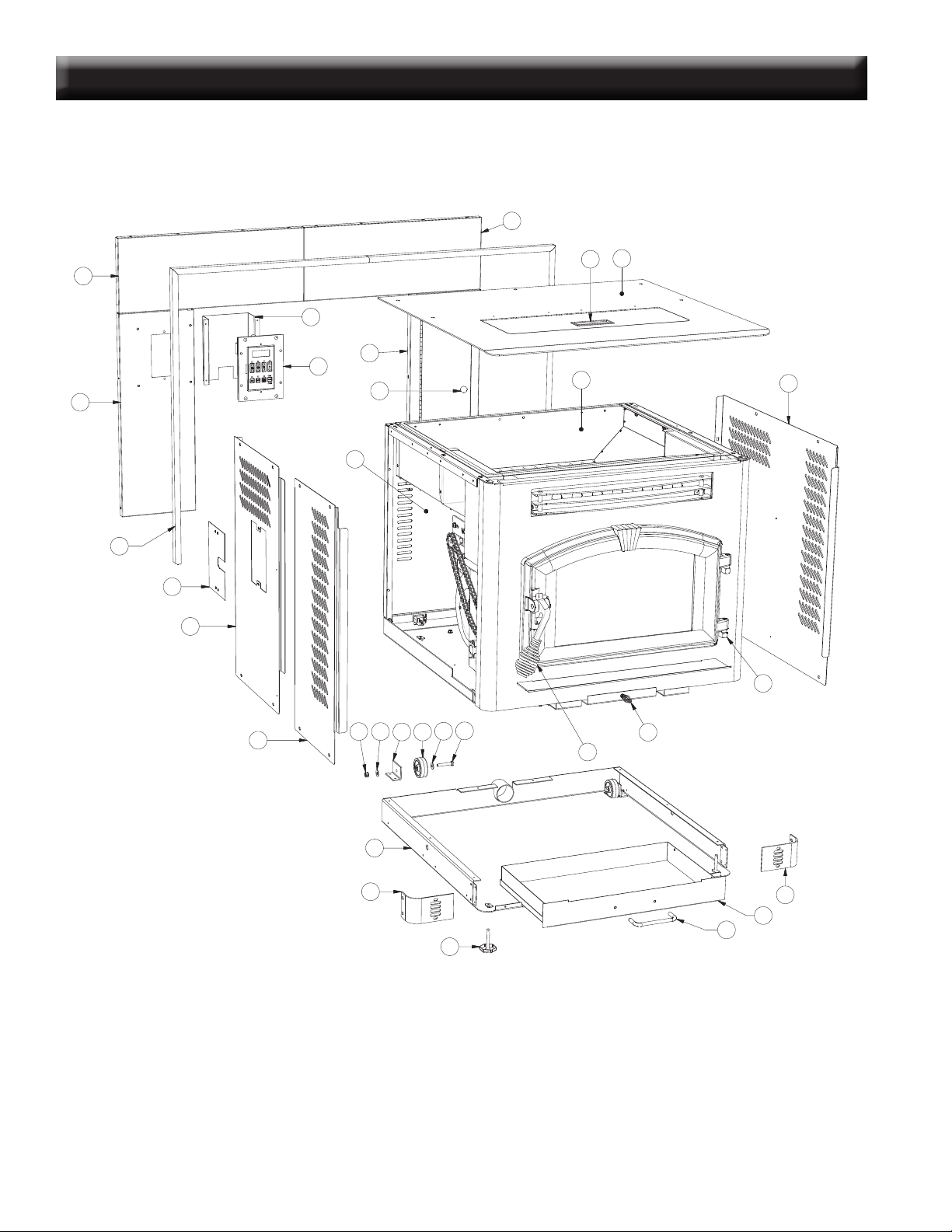
PARTS DIAGRAM - 6041TP
63
2930
68
66
39
38
34
32
31
22
23
24
26
25
59
58
60
36
35
37
33
12
40
41
48
46
45
43
42
28
27
65
64
57
61
62
56
44
47
54
55
49
52
51
50
53
3
21
20
17
18
19
11
10
13
12
72
69
14
15
16
70
2
4
1
71
69
6
7
8
9
5
67
USSC 27
PARTS LIST - 6041TP
1 69529 Pedestal 1
2 25410 Pedestal Bottom 1
3 25451 Pedestal Back 1
4 69478 Ash Pan 1
5 891137 Handle 1
6 25533 Damper/Cleanout Guide 2
7 25532 Cleanout Guide 2
8 25531 Ash Cleanout (Lower) 2
9 69528 Damper 1
10 891660 Burnpot 1
11 891059 Agitator 1
12 83529 Hair Pin 2
13 25524 Ash Cleanout (Inner) 2
14 69593 Igniter Tube Weldment 1
15 88118 Igniter Flange Gasket 1
16 80543 Igniter Cartridge 1
17 69516 Feed Door Assembly 1
18 891135 Spring Handle (Large) 1
19 25080 Door Latch 1
20 891705 Vermaculite Board (Herringbone) 1
21 69497 Louver Assembly 1
22 88116 Insulation (Kaowool) 1
23 86627 Exhaust Duct 1
24 88114 Exhaust Duct Weldment 1
25 80473 Exhaust Blower 1
26 88100 Exhaust Blower Gasket 1
27 80472 Distribution Blower 1
28 88106 Distribution Blower Gasket 1
29 69598 Hopper Assembly - Complete 1
30 80491 Micro Switch 1
31 891164 Auger Housing Weldment 1
32 891141 Auger 1
33 891132 Bottom Bushing
(
Retaining Ring - Pt #: 83534)
1
34 69514 Top Bushing Plate Assy. 1
35 891248 Bottom Plate Retainer 1
36 891195 Drive Motor Bracket 1
37 891169 Hose (2 per) 0.167 ft
38 891180 Auger Cover
39 88120 Gasket, 0.188 x 1.0 Flat FbrGlss. 0.25 ft
40 80488 Drive Motor (Auger) 1
41 80456 Drive Motor (Agitator) 1
42 891083 Sprocket, Motor 1
43 891057 Sprocket, Shaft 1
44 891058 Chain - 36 Links 1
45 69594 Primary Bushing Assembly 1
46 88111 Agitator Bracket Gasket 1
47 69595 Secondary Bushing Assembly 1
48 891706 Drive Shaft - Agitator 1
49 80549 Pressure Switch 1
50 25648 Pressure Switch Bracket 1
51 891121 Silicone Hose 0.4 ft
52 83564 Hose Clamp 1
53 89586 Auger Nipple 1
54 80381 110°F Snap Disc (Low Limit) 1
55 80390 170°F Snap Disc (High Limit) 1
56 69506 Cabinet Support, Top/Left 1
57 25448 Support Frame, Back/Left 1
58 69505 Cabinet Support, Top/Right 1
59 25447 Support Frame, Back/Right 1
60 25412 Right Cabinet Side 1
61 25411 Left Cabinet Side 1
62 80575 PCB, Circuit Board 1
N/S 80485 Wiring Harness, Main 1
63 25682 Cabinet Back 1
64 80462 Receptacle, 3-Prong 1
65 80461 Power Supply Cord 1
66
891707 Top/Lid Assembly 1
67
68 891148 Plastic Handle 1
69 25493 Corner Trim 2
70 25468 Trim, Front Panel 1
71 25472
Trim, Left Panel 1
72 25471 Trim, Right 1
N/S = Not Shown
Key Part No. Description Qty.
Key Part No. Description Qty.
Key Part No. Description Qty.
Key Part No. Description Qty.
28 USSC
PARTS DIAGRAM - 6041I
21
22
19
20
23
24
25
26
17
16
7
6
3
4
6
5
11
10
2
9
8
10
14
13
15
12
18
22
1
27
28
USSC 29
PARTS LIST - 6041I
Parts List
Key Part No. Description Qty. Key Part No. Description Qty.
1 891373 Pad, Door Hinge (Threaded) 2 17 25580 Left Side-Rear Cabinet 1
2 69547 Weldment Sub-Base 1 18 25578 Back, Cabinet 1
3 25569 Bracket, Caster 2 19 25587 Wldmt., Facade Panel Rt-Side 1
4 891424 Caster, Plastic 2 20 89943 Knob, Cabinet Door 1
5 83412 1/4-20 x 1-1/2 Hex Bolt 2 21 25585 Panel-Left Side Facade 1
6 83136 Washer 4 22 25590 Top-Panel, Facade (2 piece) 2
7 83261 1/4-20 Lock Nut 2 23 80575 Circuit Board (PCB) 1
8 69548 Weldment, Ash Pan 1 24 25583 Cover, PCB 1
9 891137 Handle (Brushed Nickel) 1 25 25582 Cover, Panel 1
10 25570 Facade, Bottom 2 26 891435 Kit, Facade Trim (B-Lux) 1
11 83479 Leveler 2 27 891135 Handle, Spring (Large) 1
12 69619 Hopper Assembly 1 28 891331 Handle, Spring (Small) 1
13 25586 Weldment, Cabinet Top 1 N/S 891299 Poker, Burnpot 1
14 891148 Handle, Plastic 1 N/S = Not Shown
Add the sufx “MB” to the part number of any painted part.
15 25581 Right Side Cabinet 1
16 25579 Left Side-Front Cabinet 1
Notice:
For all other repair components not listed above, refer to the 6041TP Repair list and
diagrams for info.
30 USSC
PARTS DIAGRAM/LIST
4
3
1
5
6
7
2
9
8
10
11
1
1
2
2
3
3
4
4
A A
B B
1 86623
LOUVER
3
2 83531
SCREW, STAINLESS
2
3 83532
SPACER
4
4
83530 HEX NUT, STAINLESS 2
5
25444 LOUVER BRACKET (LEFT) 1
6 25445 LOUVER BRACKET (RIGHT) 1
PARTS LIST
ITEM
PART NO
TITLE
QTY
2
3
1
6
4
5
2
1
3
4
6041HF Parts Diagram & List
NOTE:
For internal parts, cabinet parts, etc. see pages 21-22
Louver Assembly (Part No.: 69540)
REAR VIEW-PERSPECTIVE
SCALE 3 / 4
TOP VIEW
SCALE 1 : 1
1
1
2
2
3
3
4
4
A A
B B
TOLERANCES
EXCEPT
AS
NOTED
HOLES
+
.005" -.001"
DECIMAL
.XX = 0.03 XXX = 0.010
ANGULAR
`
2
~
DESCRIPTION
BLANK NUMBER
REFERENCE
SCALE
DWN BY
DATE
SIZE
REV
TITLE NUMBER
UNITED STATES STOVE COMPANY
ESTABLISHED 1869
STEEL LEG w/GUSSET 891216
AB
CDB
10/20/2005
1
OF
3
SHEET
3:4
REVISION HISTORY
REV DESCRIPTION DATE BY
A INITIAL RELEASE 10/20/2005 CDB
.25 1
2 PLCS
0.63
0.63
1a
Parts List
Key Part No. Description Qty. Key Part No. Description Qty.
1 25491 Feed Door 1 7 891131 Glass Ceramic 1
2 25492 Handle, Door 1 8 25464 Retainer, Top Glass 1
3 83506 Roll Pin, 3/8 x 1-1/4 1 9 25465 Retainer, Bottom Glass 1
4 891135 Handle, Spring (Parts Bag) 1 10 83202 Machine Screw 4
5 88112 Gasket, 1/2” Sq. Rope 5 ft 11 83278 #10 Flat Washer 4
6 88087 Gasket, Glass (1 x 3/16) 4 ft
Parts List
Key Part No. Description Qty.
1 891334 Louver, Stainless Steel 3
2 83531 Screw, 10-24UNC x 2” Long 2
3 83532 Spacer 4
4 83295 Nut, 10-24 UNC 2
5 25444 Bracket, Louver (Left) 1
6 25445 Bracket, Louver (Right) 1
Parts List
Key Part No. Description Qty.
1 25523 Leg, Cast Iron 4
1a 891216 Leg, Steel (alternate to item 1) -
2 25425 Guide Rail, Ash Pan 2
3 69622B Ash Pan Weldment 1
4 891138 Handle, Nickel 1

USSC 31
NOTE
32 USSC
This manual will help you obtain efcient, dependable service from the furnace, and
enable you to order repair parts correctly.
Keep this manual in a safe place for future reference.
When placing an order or for warranty claims, please provide the following informa-
tion found on the Certication Plate located below the ash door.
PART NUMBER
PART DESCRIPTION
MODEL NUMBER - 6041 / 6041TP / 6041HF / 6041I
SERIAL NUMBER______________
227 Industrial Park Road
P.O. Box 151
South Pittsburg, TN 37380
(423) 837-2100
Customer Service: (800)-750-2723 • Repair Parts: (888) 299-1440