service@thorgroup.us +1 877-288-8099
THOR KITCHEN OUTDOOR Appliance Cabinet Installation Manual
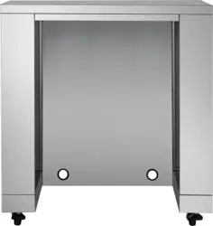
MODEL# MK02SS304 (Appliance Not included)
IMPORTANT:
Save for electrical inspector’s use.
Installer: Leave installation instructions with the homeowner.
Homeowner: Keep installation instructions for future reference

service@thorgroup.us +1 877-288-8099
Welcome
Thank you for purchasing your Thor Kitchen Appliance! We appreciate
your business and we recommend that you read this entire User’s
Manual before operating your new appliance for the first time.
This manual contains instructions on how to properly install and set up
your new range, as well as insights into the unique features that our
product offers. Please keep this manual for future reference, as it
contains answers to questions that you might have as you begin to cook.
For any inquiries, please reach our customer service support at +1 877-
288-8099 at our business hours or email service@thorgroup.us.
Thank you,
Thor Group
This manual applies to the following models’ series:
Model # MK02SS304 (Outdoor Appliance Cabinet)
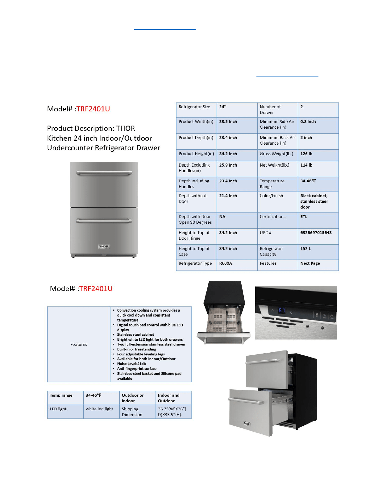
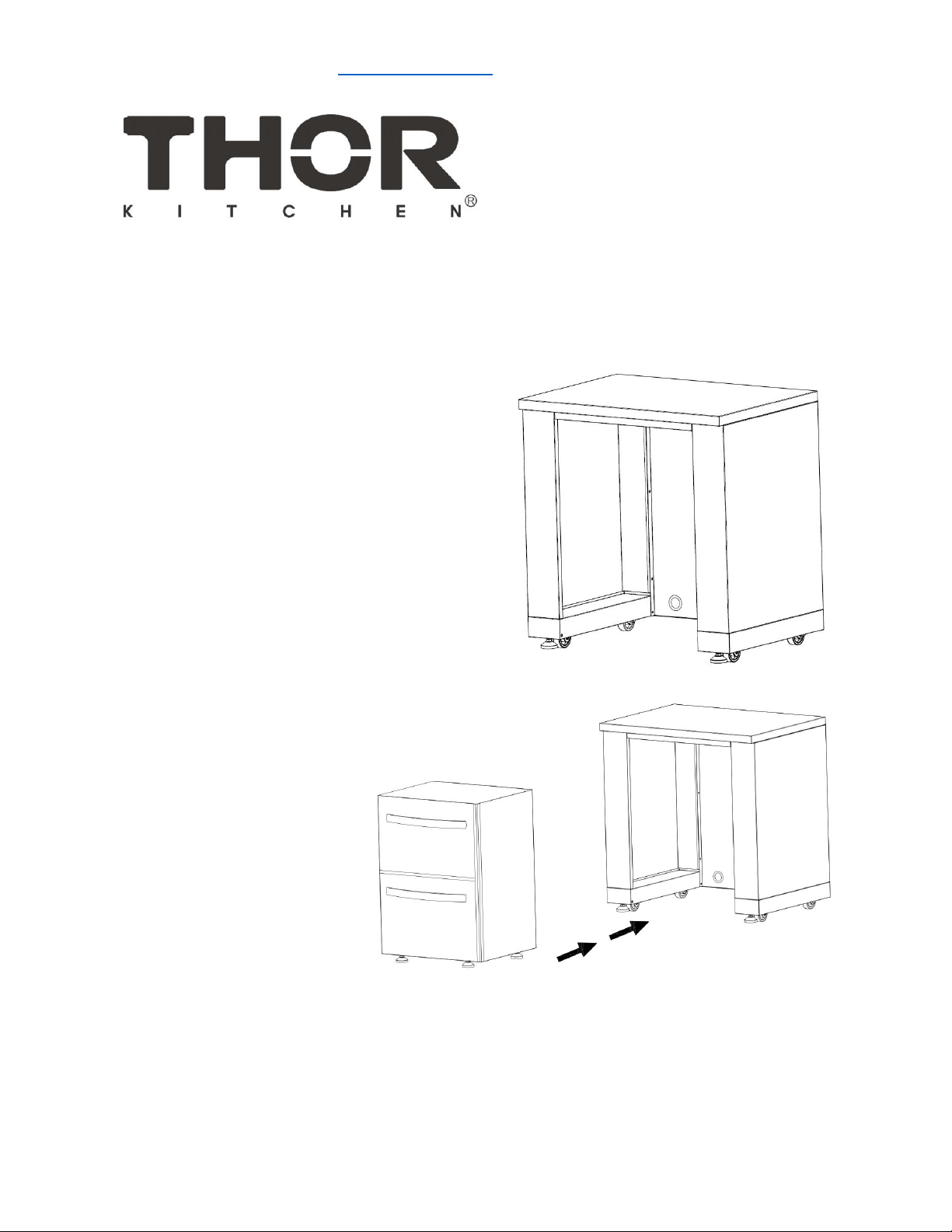
Model # TRF2401U (Outdoor Two-drawer under cabinet refrigerator)
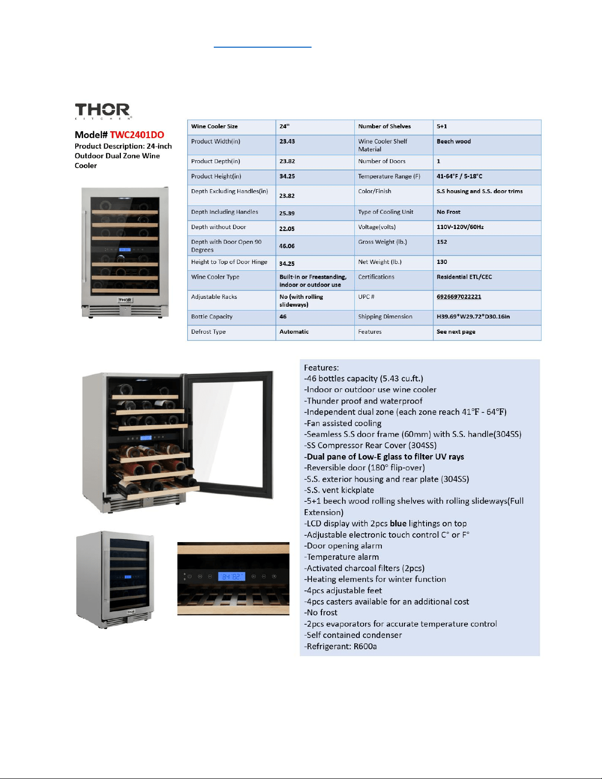
Model # TWC2401DO (Outdoor Wine Cooler)

service@thorgroup.us +1 877-288-8099
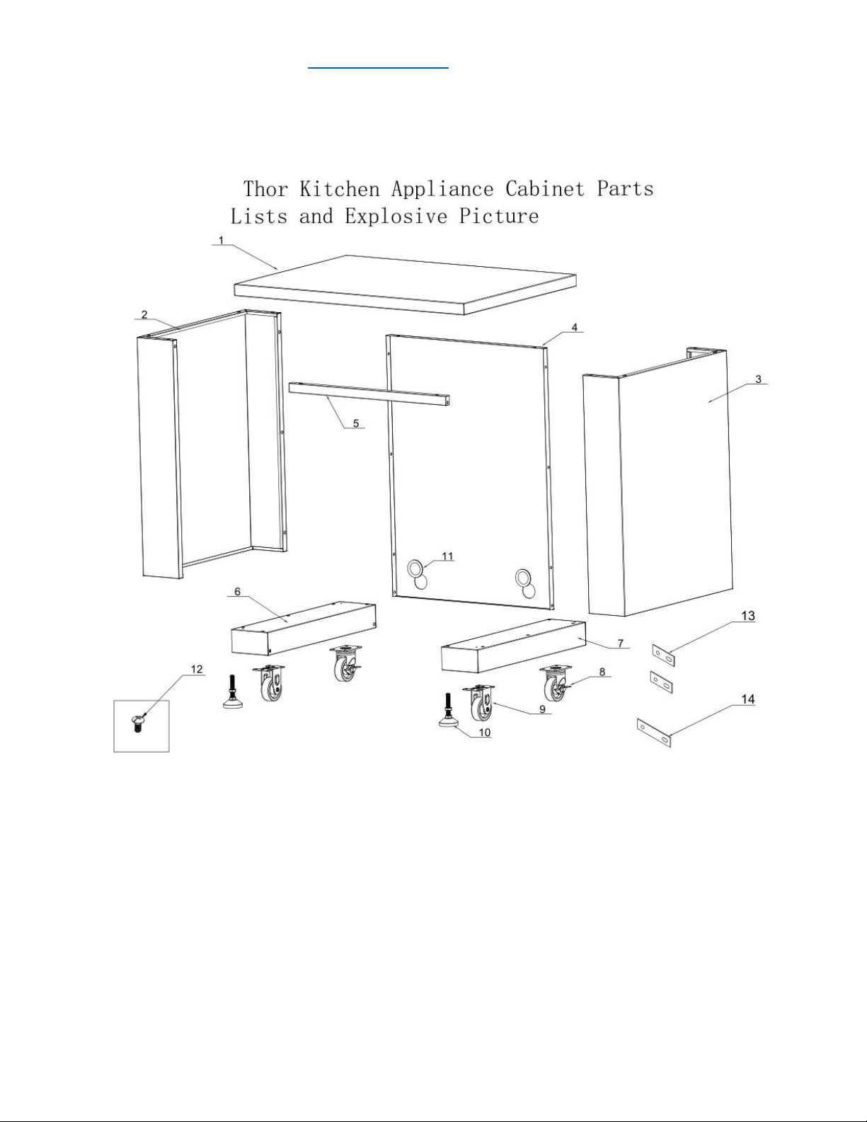
Parts List
If you are missing any part, please contact Thor Kitchen Customer Service Department at 877-
288-8099 at business hours, or email service@thorgroup.us for help.
Explosive #
Part #
Part Name
Quantity
1
20.01.008041-000-A0
Countertop welding assembly
1
2
20.01.001030-000-A0
Left side panel welding assembly
1
3
20.01.001031-000-A0
Right side panel welding assembly
1
4
20.01.001032-000-A0
Back panel welding assembly
1
5
20.01.001033-000-A0
Beam welding assembly
1
6
20.01.008042-000-A0
Right bottom panel welding assembly
1
7
20.01.008043-000-A0
Left bottom panel welding assembly
1
8
05.10.000123-000-A0
Universal caster with brake
2
9
05.10.000122-000-A0
Fixed caster
2
10
05.01.008004-000-A0
Supporting leg
2
11
06.08.008078-000-A0
Rubber gasket
2
12
06.02.000093-000-A0
Philips thumb head screw with anti-slip design
56
13
04.01.002580-000-A0
cabinet back connecting plate
2
14
04.01.002579-000-A0
cabinet front connecting plate
1
service@thorgroup.us +1 877-288-8099
Cabinet Installation
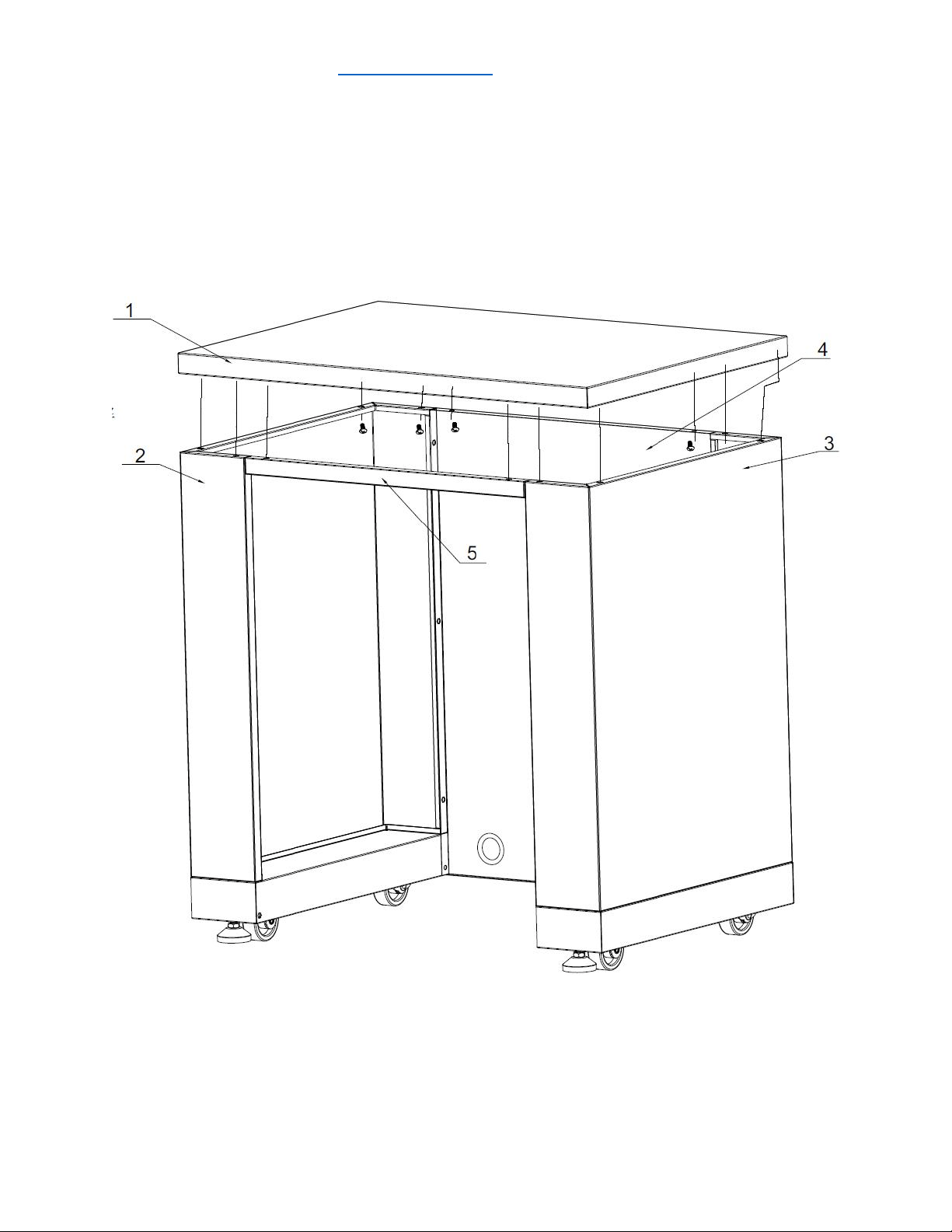
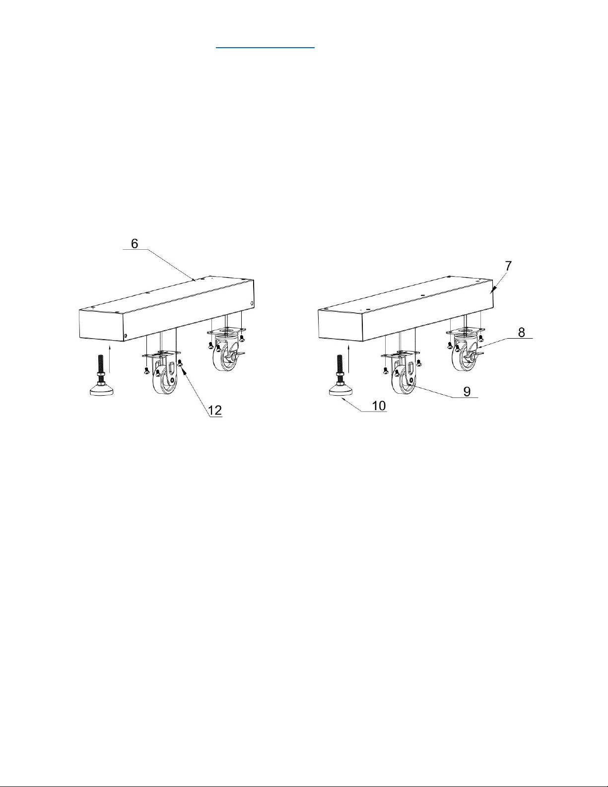
Step 1
1. Install 2 pcs Supporting Leg (Part # 10) to bottom right welding assembly (Part # 6) and
bottom left welding assembly (Part # 7). Use hand to adjust the supporting leg to the
suitable position;
2. Use 16 pcs ¼” flat Philip’s head screw (Part # 12) to connect 2 pcs fixed caster (Part # 9)
and 2 pcs universal casters (Part # 8) to Part #6 and #7.
service@thorgroup.us +1 877-288-8099
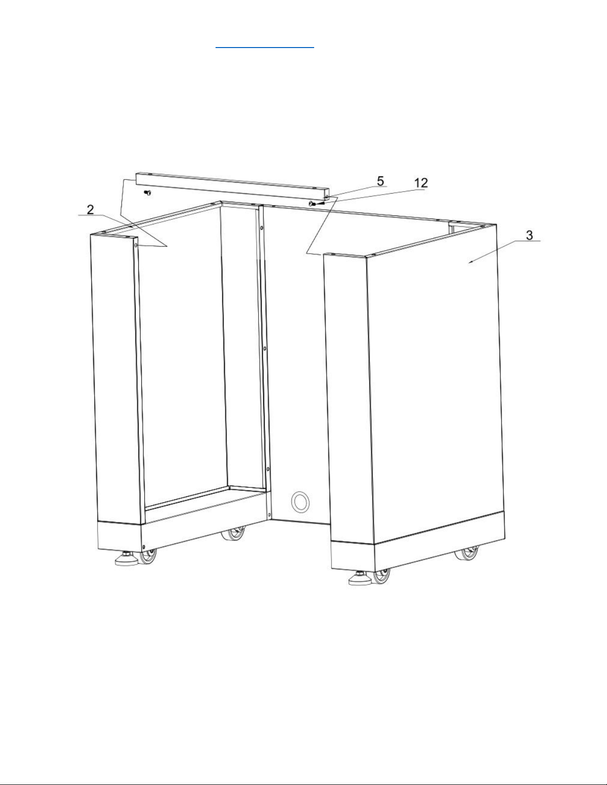
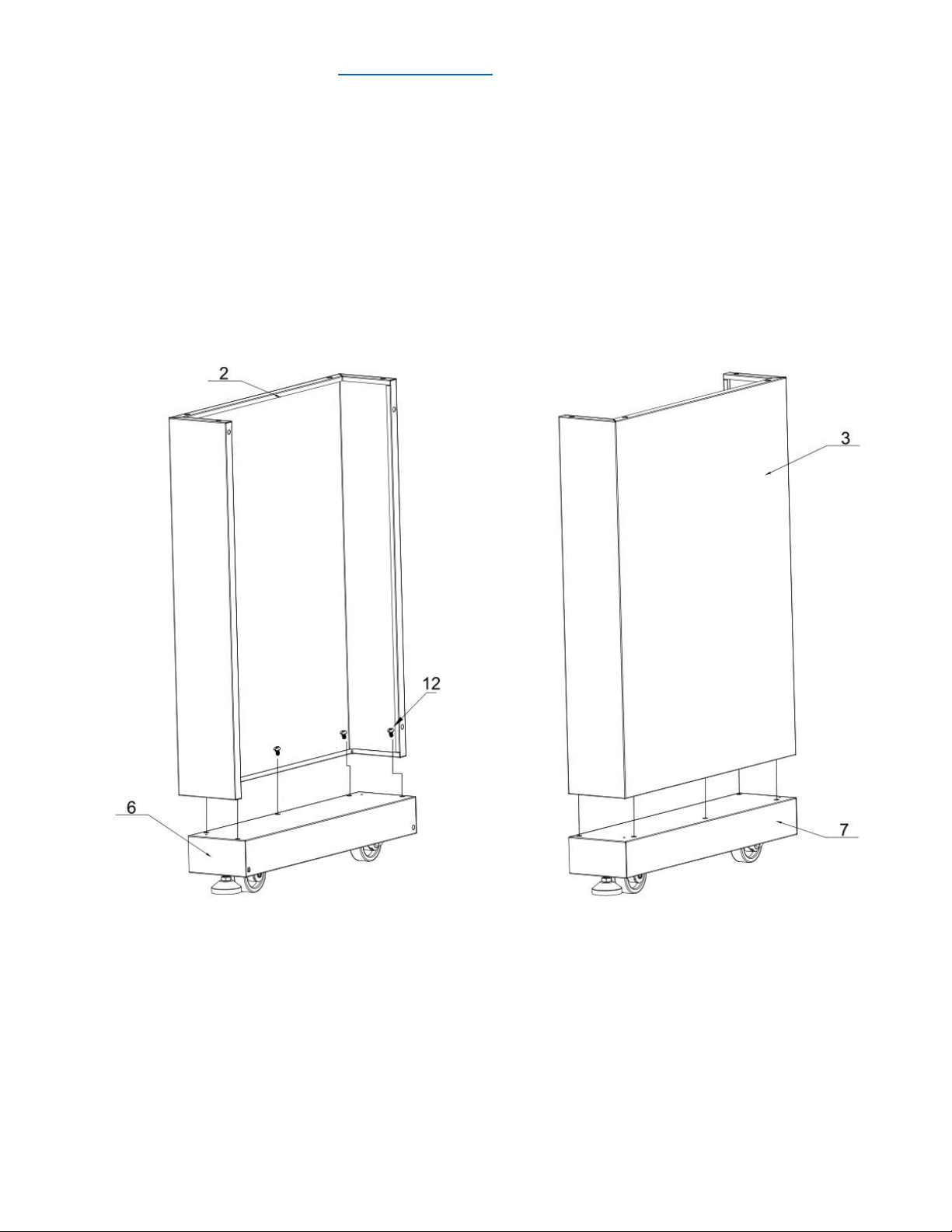
Step 2
1. Use 5 pcs ¼” flat Philip’s head screws (part # 12) to connect left side panel (Part # 2) to
Part #6;
2. Use 5 pcs ¼” flat Philip’s head screws (part # 12) to connect right side panel (Part # 3) to
Part #7;
3. Do not over-tighten all the screws until parts are lined up.
service@thorgroup.us +1 877-288-8099
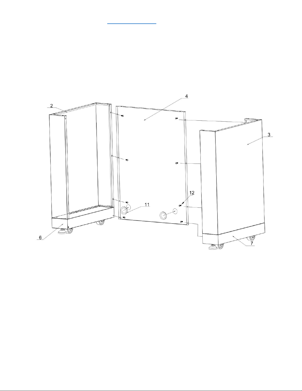
Step 3
1. Install 2 pcs rubber gaskets (Part # 11) to Back Panel (Part # 4);
2. Use 4 pcs ¼” flat Philip’s head screws (Part # 12) to connect Part #4 to Part #2 and #6;
3. Use 4 pcs ¼” flat Philip’s head screws (Part # 12) to connect Part #4 to Part #3 and #7;
4. Do not over-tighten all the screws until parts are lined up.