service@thorgroup.us +1 877-288-8099
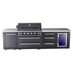
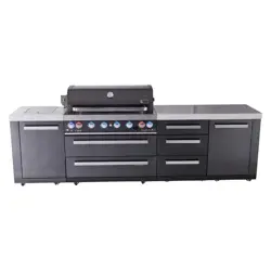
Outdoor Grill Cabinet Installation Manual
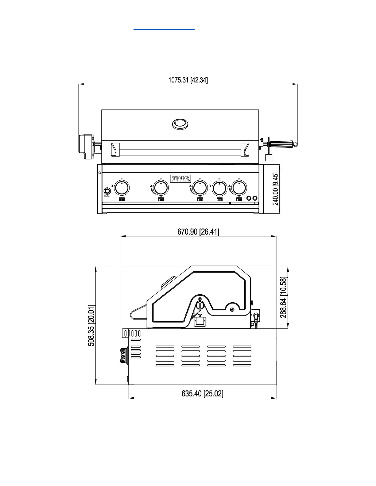
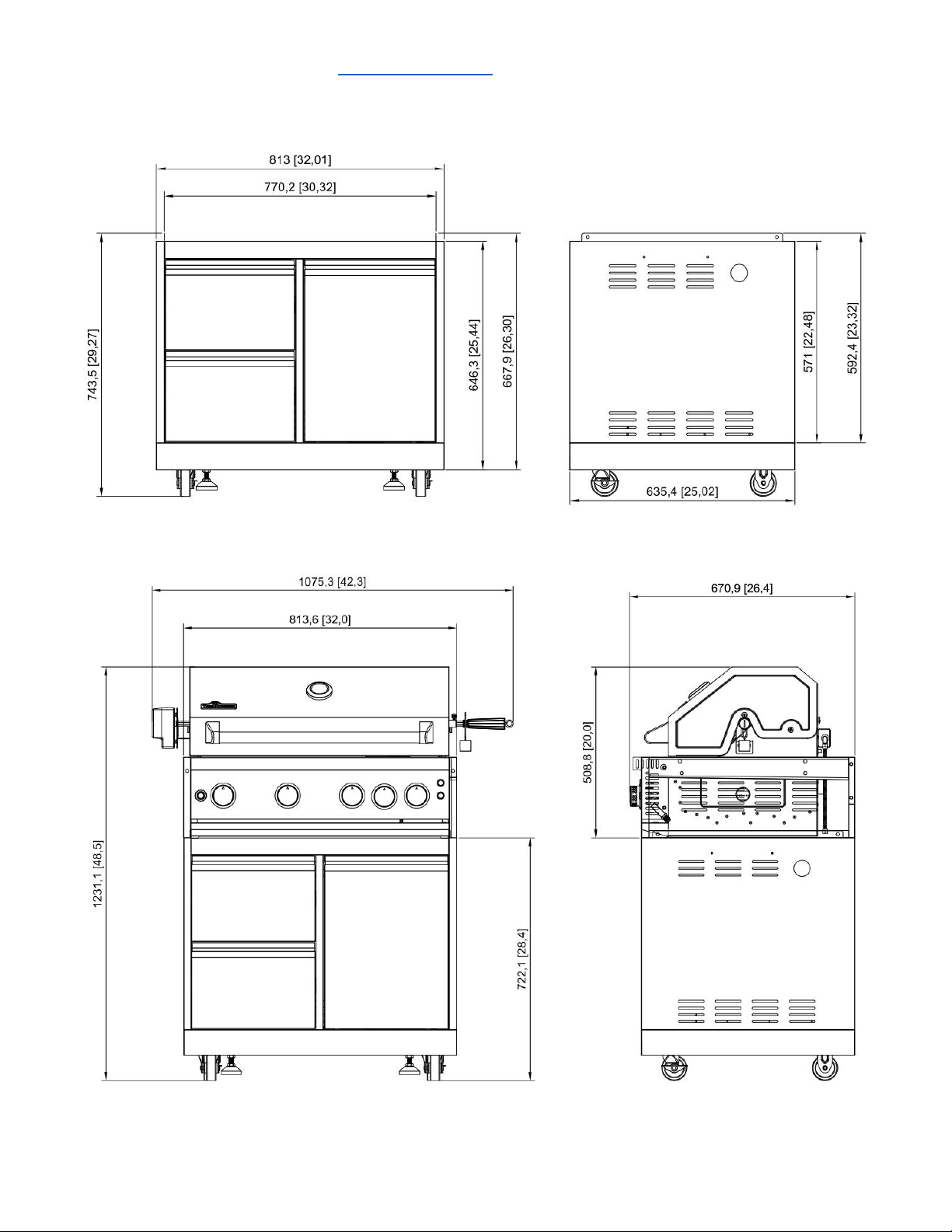
MODEL# MK04SS304 Thor Kitchen Outdoor BBQ Grill (MK03SS304 for Cabinet)
IMPORTANT:
Save for electrical inspector’s use.
Installer: Leave installation instructions with the homeowner.
Homeowner: Keep installation instructions for future reference

service@thorgroup.us +1 877-288-8099
Warnings
These are the most critical warnings summarized below.
***WARNING***
• If the instructions in this manual are not followed exactly, a fire or explosion
may result, causing property damage, personal injury or death.
• Do not store or use gasoline or other flammable substances and liquids near
this or other appliance,
• Installation of this appliance must be done by a qualified, service agency or gas
supplier.
What to do if you smell gas
• Do not light any appliance
• Do not touch an electrical switch
• Immediately call the gas supplier from a neighbor’s phone
• Follow the gas supplier’s instructions
• If you cannot reach the gas supplier, call the fire department

service@thorgroup.us +1 877-288-8099
Welcome
Thank you for purchasing your Thor Kitchen Appliance! We appreciate your
business and we recommend that you read this entire User’s Manual before
operating your new appliance for the first time.
This manual contains instructions on how to properly install and set up your new
range, as well as insights into the unique features that our product offers. Please
keep this manual for future reference, as it contains answers to questions that you
might have as you begin to cook.
For any inquiries, please reach our customer service support at +1 877-288-8099
Thank you,
Thor Group
This manual applies to the following models’ series:
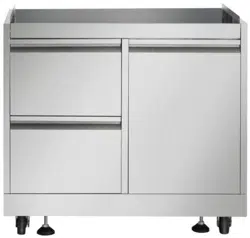
Model # MK03SS304 (Outdoor Grill Cabinet)
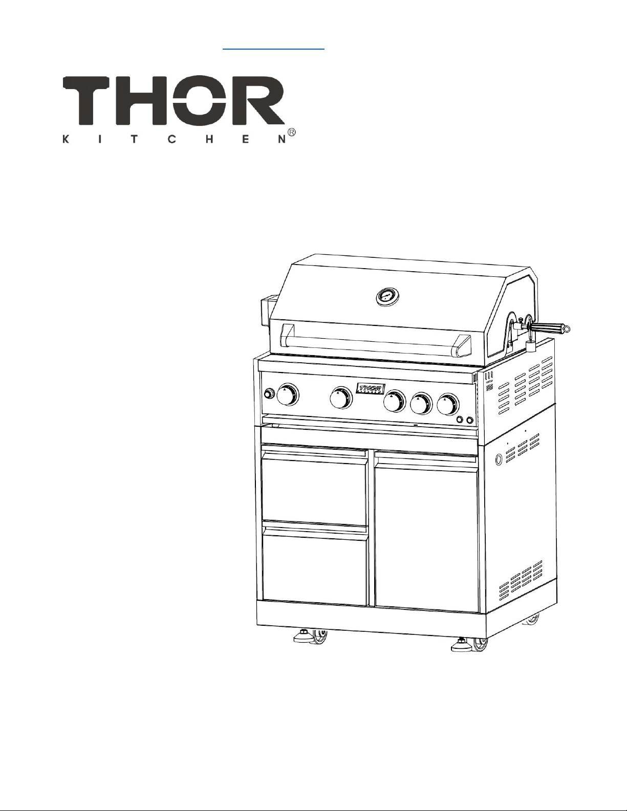
Model # MK04SS304 (Outdoor BBQ Grill)
service@thorgroup.us +1 877-288-8099
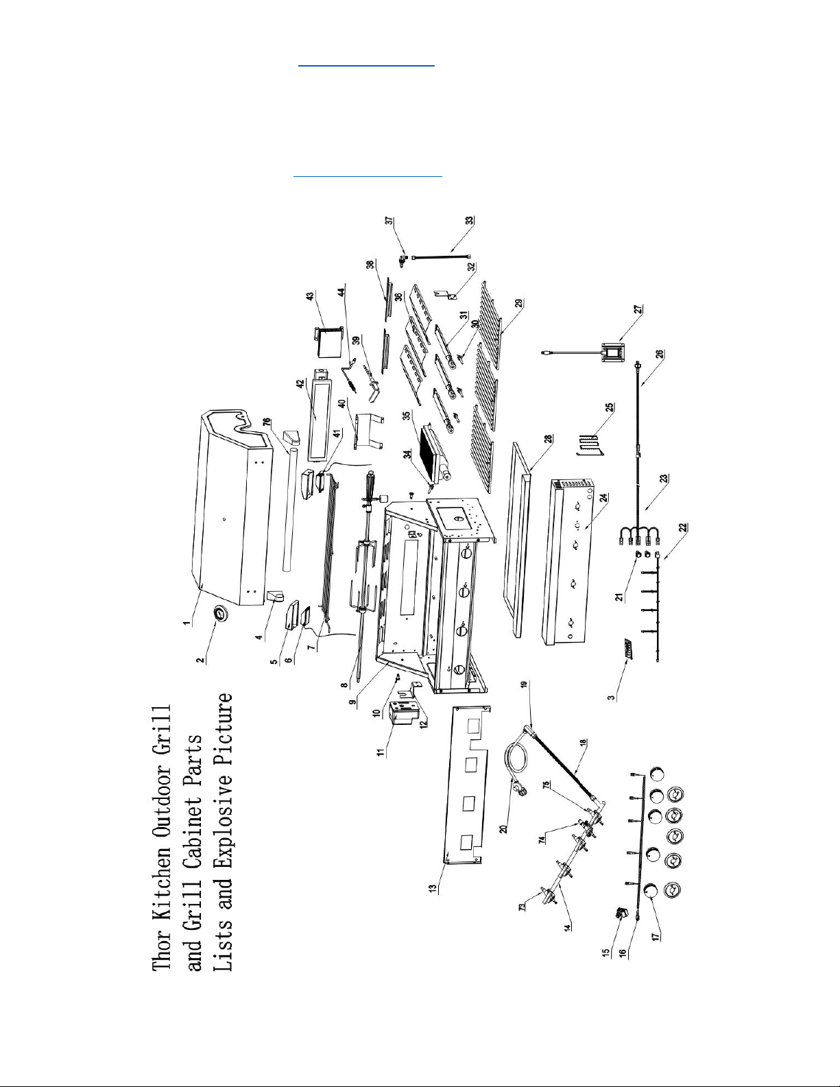
Parts Explosive Pictures
If you are missing any part, please contact Thor Kitchen Customer Service Department at +1 877-288-
8099 at business hours, or email se[email protected] for help. Please provide your proof of purchase
for warranty verification.

service@thorgroup.us +1 877-288-8099
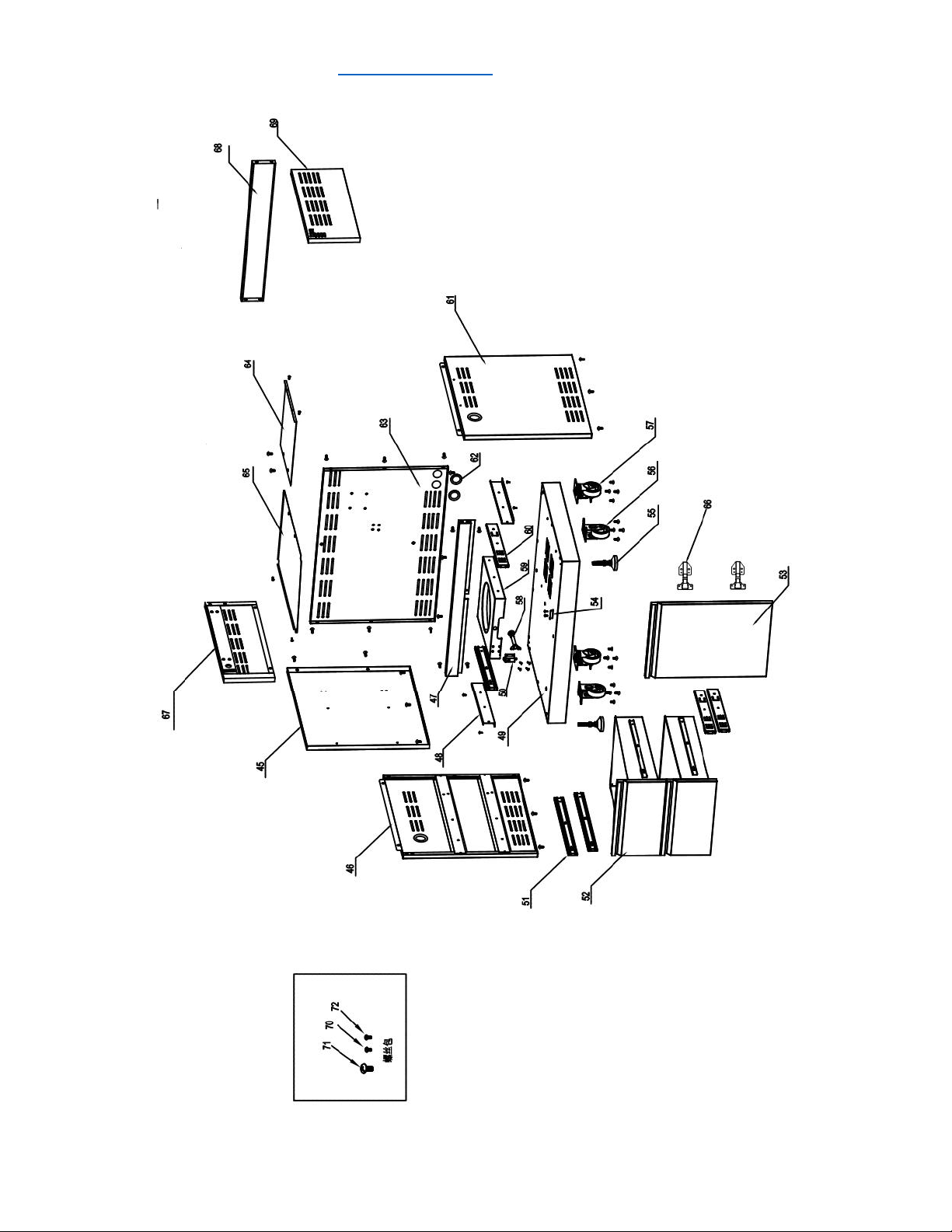
Parts List
Explosive
#
Part #
Part Name
Quantity
1
22.99.008092-000-A0
Grill Top Cover
1
2
05.99.008024-000-A0
Thermometer
1
3
08.01.008041-000-A0
logo
1
4
12.02.000070-000-A0
left handle holder
1
5
04.01.008107-000-A0
Light Cover
2
6
07.04.008001-000-A0
Light #1
1
7
13.99.008002-000-A0
Top warming rack
1
8
05.99.008011-000-A0
Rotisserie
1
9
22.99.009207-000-A0
Grill Cavity
1
10
06.07.008002-000-A1
Top cover rotary pin
2
11
07.14.008001-000-A0
Motor
1
12
04.01.008057-000-A0
Motor holder
1
13
04.03.008002-000-A1
Burner valve holding plate
1
14
22.99.009209-000-A0
Main manifold
1
15
07.07.008004-000-A0
5-point Spark Module
1
16
07.06.008003-000-A0
Main burner ignition harness
1
17
14.01.008001-000-A0
Main Burner Knob
5
18
11.01.008001-000-A0
corrugated pipe
1
19
05.07.008001-000-A0
Embedded joint
1
20
07.99.000266-000-A0
Gas regulator and gas pipe
1
21
07.02.008012-000-A0
Metal push button
2
22
07.06.008006-000-A0
Main burner knob light wiring
1
23
07.06.008002-000-A0
Main switch wiring
1
24
19.07.008002-000-A0
Grill control panel
1
25
05.09.008002-000-A0
match holder
1
26
07.06.008005-000-A0
Main burner power plug
1
27
07.14.008002-000-A0
American-standard transformer
1
28
20.01.008015-000-A2
Grease tray
1
29
13.02.008002-000-A0
Cooking rack
1
30
10.09.008009-000-A0
Main burner electrode
3
31
10.01.008002-000-A2
Tube burner
3
32
04.01.008058-000-A0
Rotisserie holder
1
33
10.04.008002-000-A0
Back broil burner corrugated pipe
1
34
10.09.008010-000-A0
Front broil burner electrode
1
35
10.10.008007-000-A0
Infrared broil burner
1

service@thorgroup.us +1 877-288-8099
36
04.01.008051-000-A0
flame tamer
3
37
10.05.008002-000-A0
Back broil burner orifice - LP
1
38
20.01.008014-000-A1
flame transferring welding plate
2
39
10.09.008004-000-A0
Back broiler burner electrode
1
40
04.01.008060-000-A1
Back broiler burner protection cover
1
41
07.04.008002-000-A0
Light #2
1
42
10.99.008001-000-A0
Back broil burner
1
43
04.01.008053-000-A0
gas-collecting hood
1
44
10.99.008002-000-A0
Temperature rod
1
45
20.01.008086-000-A0
Clapboard welding part
1
46
20.01.008082-000-A0
Left side panel A welding assembly
1
47
20.01.008087-000-A0
beam welding assembly
1
48
04.01.008119-000-A0
LP tank supporting slide
2
49
20.01.008079-000-A0
tank bottom welding assembly
1
50
05.17.008003-000-A0
Snap bolt
1
51
05.14.008001-000-A0
Slideway
4
52
22.99.009199-000-A0
Drawer assembly
2
52.1
20.01.008051-000-A0
drawer front panel welding plate
2
52.2
04.01.008179-000-A0
drawer front panel lining
2
52.3
04.01.008180-000-A0
drawer middle plate
2
52.4
04.01.008181-000-A0
drawer bottom plate
2
53
22.99.009217-000-A0
Door assembly
1
54
04.01.002596-000-A1
Door barrier strip
1
55
05.01.008004-000-A0
Supporting leg
2
56
05.10.000122-000-A0
Fixed caster
2
57
05.10.000123-000-A0
Universal caster with Brake
2
58
05.13.008153-000-A0
Tank fixing rod
1
59
04.01.008117-000-A0
Tank bottom support
1
60
05.14.008012-000-A0
14" Sliders
4
61
20.01.008080-000-A0
Right side panel A welding assembly
1
62
06.08.008078-000-A0
Rubber gasket
4
63
20.01.008084-000-A0
Back panel A welding assembly
1
64
04.01.008183-000-A0
gas tank heat shield
1
65
04.01.008182-000-A0
Laminate board
1
66
05.03.008001-000-A0
Door Hinge
2

service@thorgroup.us +1 877-288-8099
67
20.01.008083-000-A0
Left side panel B welding assembly
1
68
20.01.008085-000-A0
Back Panel B welding assembly
1
69
20.01.008081-000-A0
Right side panel B welding assembly
1
70
06.10.000022-000-A0
5/32“Philips thumb head screw
52
71
06.02.000093-000-A0
1/4“*14 Philips thumb head screw with anti-
slip design
59
72
06.11.008056-000-A0
5/32" *8 flat head screw
12
73
09.01.008008-000-A0
front broil burner valve
1
74
09.04.008003-000-A0
back broil burner valve
1
75
09.01.008007-000-A0
main burner valve
3
76
12.01.008002-000-A0
Top cover handle
1
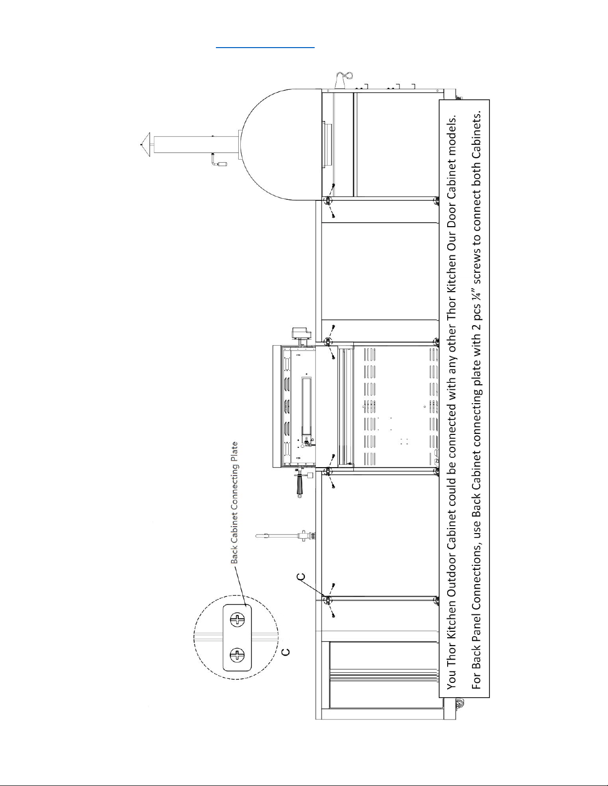
77
04.01.002580-000-A0
cabinet back connecting plate
2
service@thorgroup.us +1 877-288-8099
Cabinet Installation
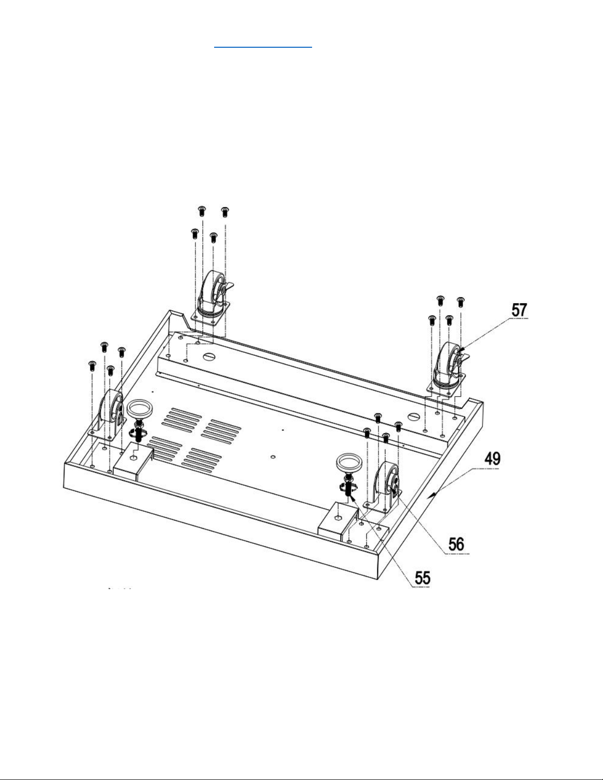
Step 1
1. Flip the bottom base welding assembly (Part #49) so in order to install legs and casters
2. Use 16 pcs ¼” *14 Philips thumb head screw with anti-slip design (Part #71) to install 2 pcs
supporting legs (Part #55), 2 pcs fixed casters (Part #56) and 2 pcs universal casters with brake (Part
#57)
service@thorgroup.us +1 877-288-8099
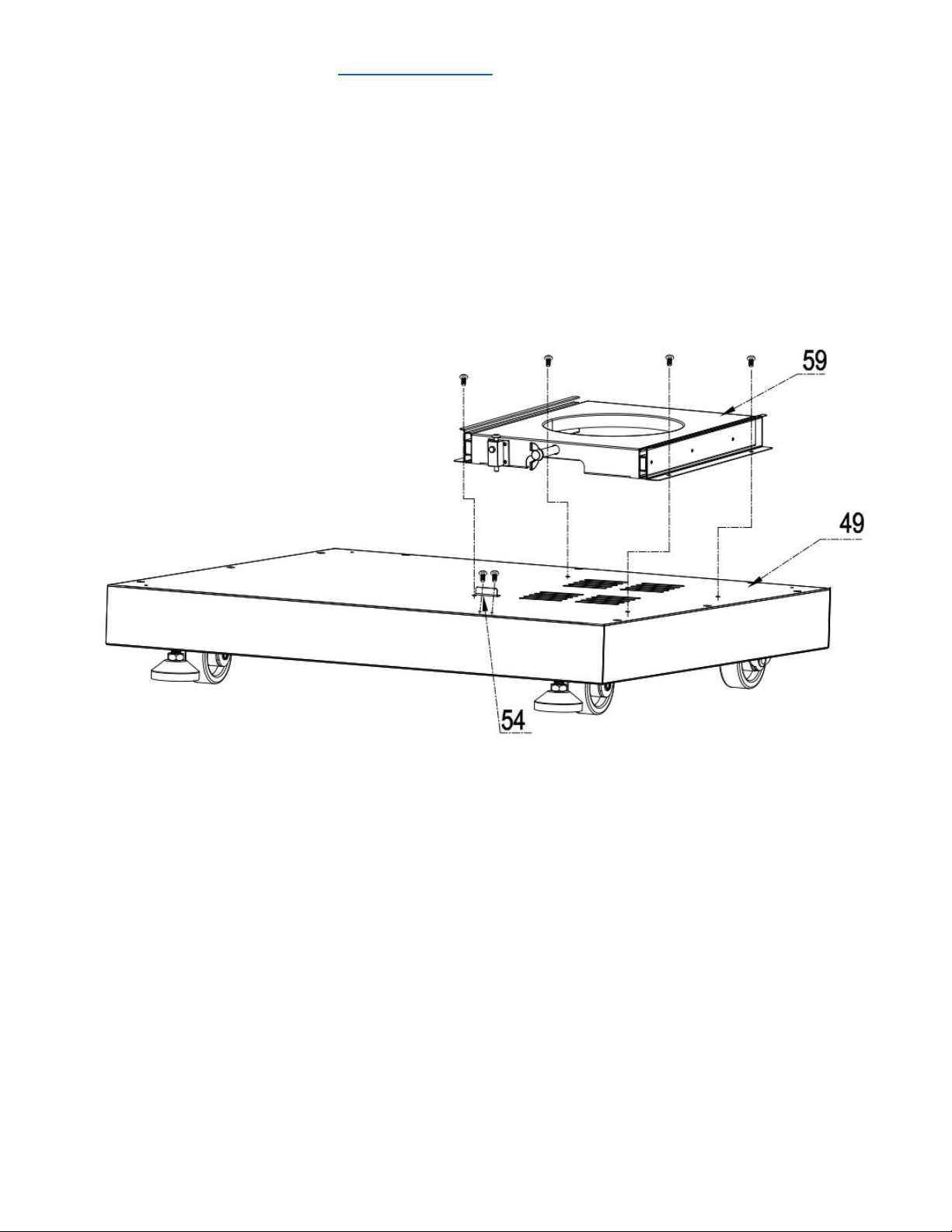
Step 2
1. Flip back the bottom base after casters and legs are installed;
2. Use 4 pcs 5/32” *8 flat head screw (Part # 72) to connect Tank bottom support (Part # 59) to
bottom base welding assembly (Part # 49);
3. Use 2 pcs 5/32” *8 flat head screw (Part # 72) to connect Door barrier strip (Part # 54) to
bottom base welding assembly (Part #49);
service@thorgroup.us +1 877-288-8099
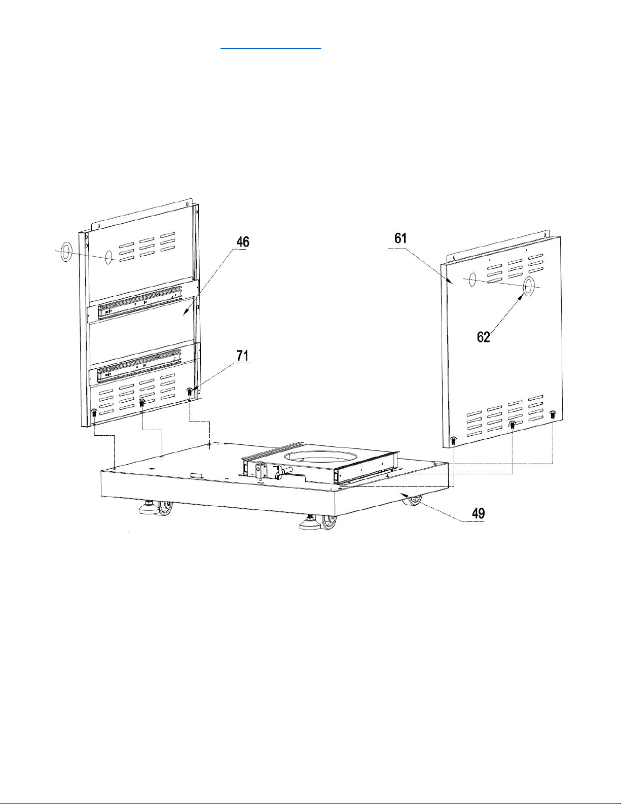
Step 3
1. Use 6 pcs 1/4“*14 Philips thumb head screw with anti-slip design (Part #71) to Left side panel A
welding assembly (Part #46) and Right-side panel A welding assembly (Part # 61) to bottom
base welding assembly (Part #49);
2. Attach 2 pcs Rubber gaskets to related position on Part #46 and Part #61;
service@thorgroup.us +1 877-288-8099
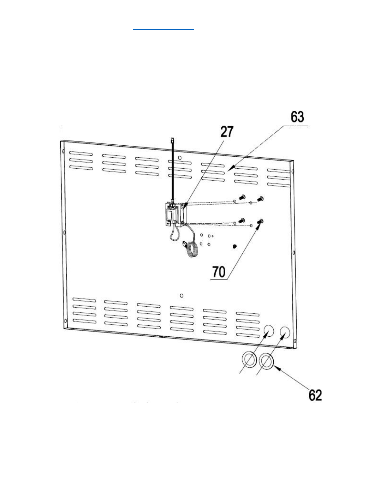
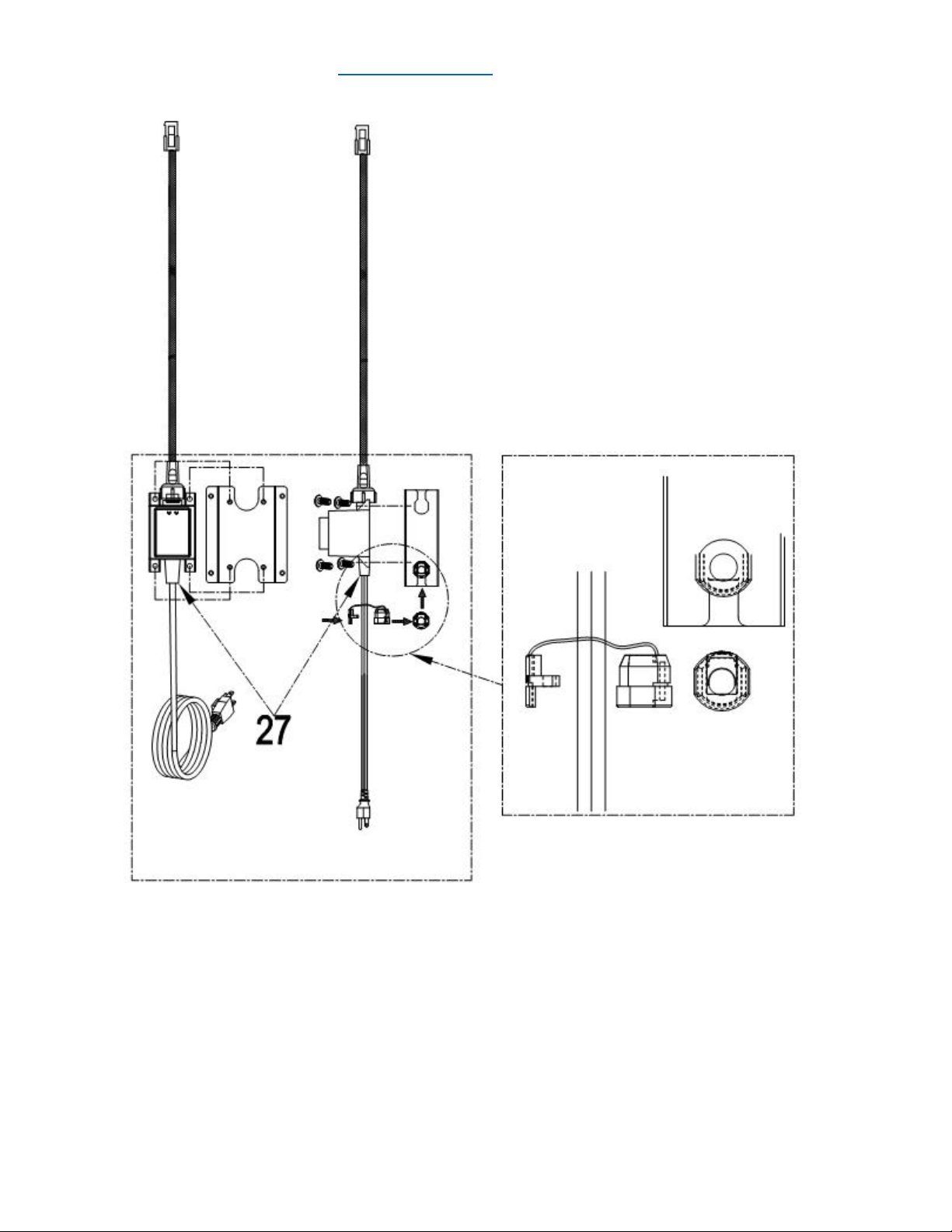
Step 4
1. Use 4 pcs 5/32” *8 flat head screw (Part # 72) to install American-standard transformer (Part #
27) on Back panel A welding assembly (Part # 63); Do not break the power plug on the bottom
and the buckle on the top.
2. Attach 2 pcs Rubber gasket (Part # 62) to related position on Part # 63;
service@thorgroup.us +1 877-288-8099
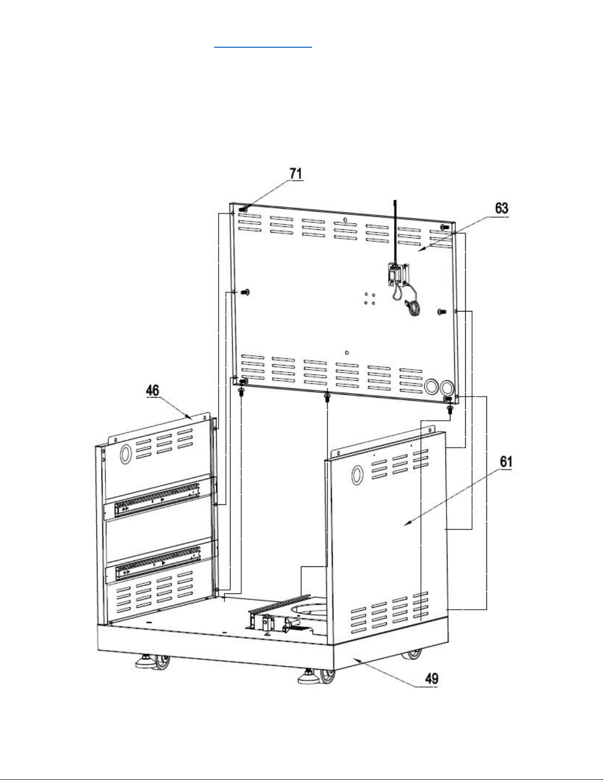
Step 5
1. Use 3 pcs 1/4“*14 Philips thumb head screw with anti-slip design (Part #71) to install Back
panel A welding assembly (Part # 63) to bottom base welding assembly (Part # 49);
2. Use 3 pcs 1/4“*14 Philips thumb head screw with anti-slip design (Part #71) to connect Back
panel A welding assembly (Part # 63) with Part # 46 and # 61
service@thorgroup.us +1 877-288-8099
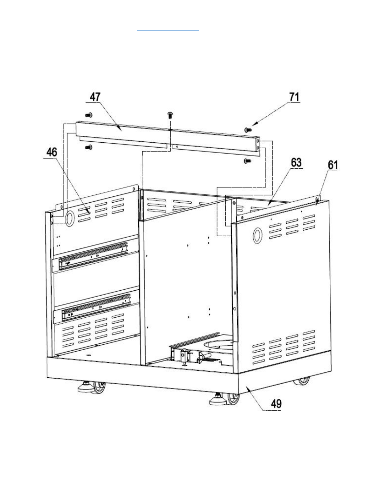
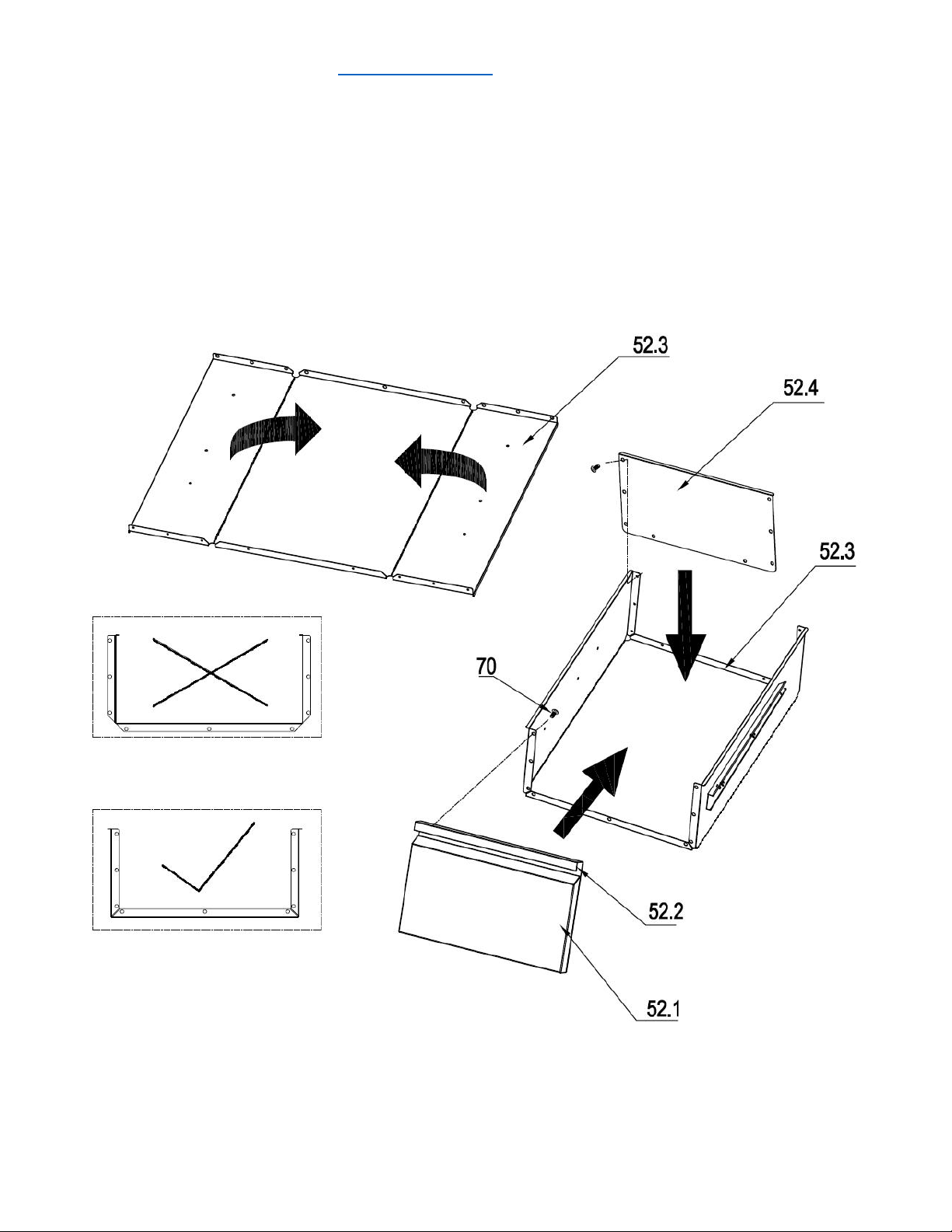
Step 8
1. Check the edge of the middle plate of the drawer assembly (Part #52) and make sure the side
with edge is facing up; otherwise you will get to wrong folding direction (see the picture below
with wrong folding direction with “×”). Be careful with the folding process.
2. Use 8 pcs 5/32 flat Philip’s screw heads (Part # 70) install the bottom plate of drawer assembly
(Part# 52.4) to the middle plate (Part# 52.3)
3. Use 8 pcs 5/32 flat Philip’s screw heads (Part # 70) install the front plate of drawer (Part#
assembly to the middle plate (Part# 52.1 and 52.2)
service@thorgroup.us +1 877-288-8099
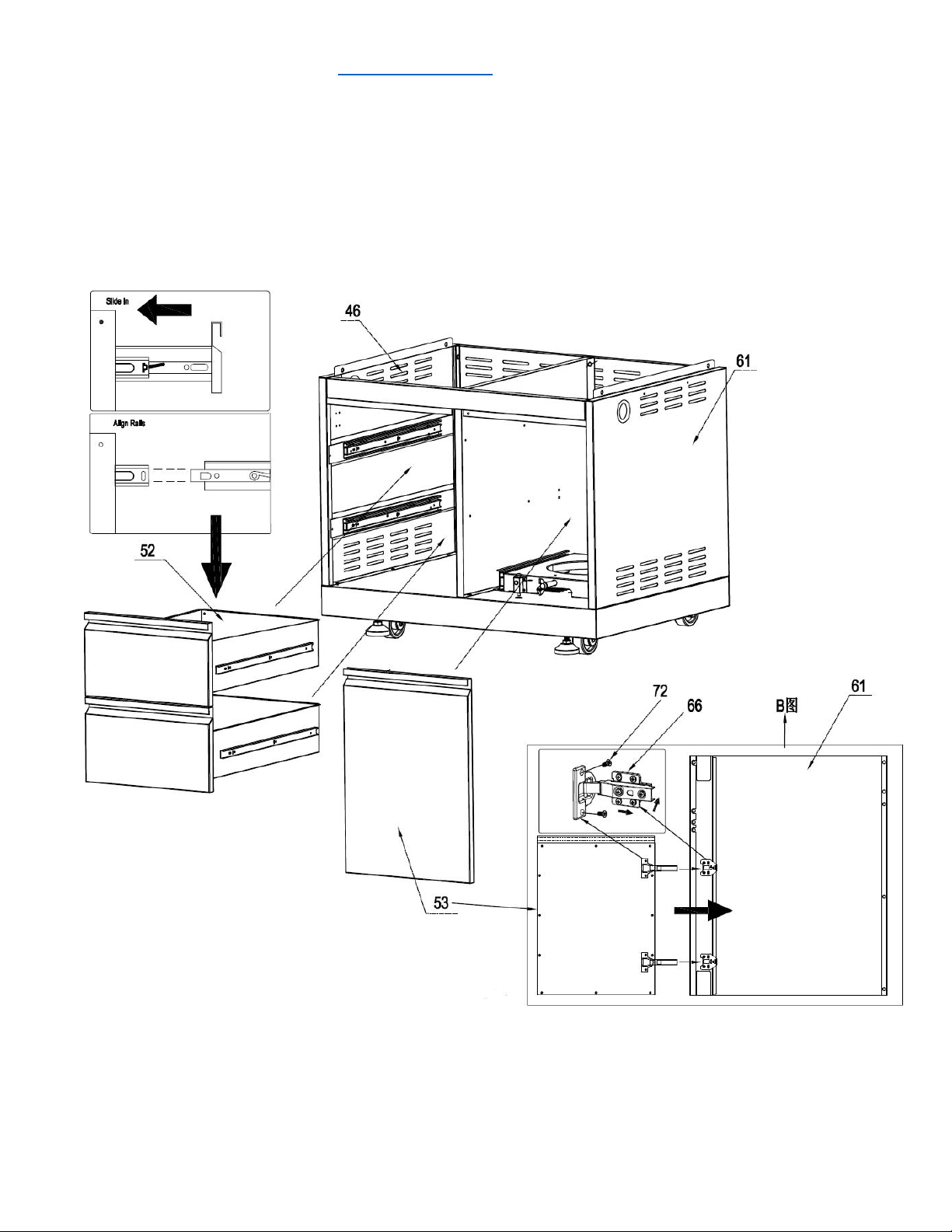
Step 9
1. Insert 2 pcs drawer assemblies (Part #52) into cabinet body;
2. Divide the two parts from door hinge (Part #66) and use 5/32” *8 flat head screw (Part #72) to install
them to right side panel (Part #61) and cabinet door (Part #53)
3. Follow the requirement in the picture to install cabinet door (Part # 53)
service@thorgroup.us +1 877-288-8099
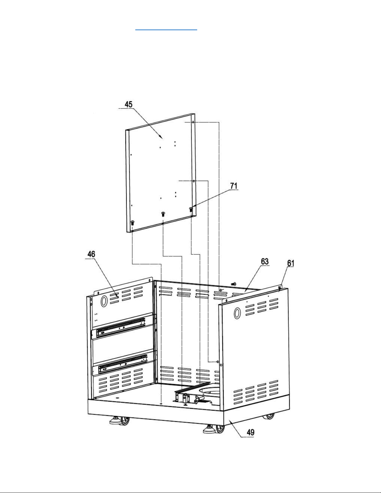
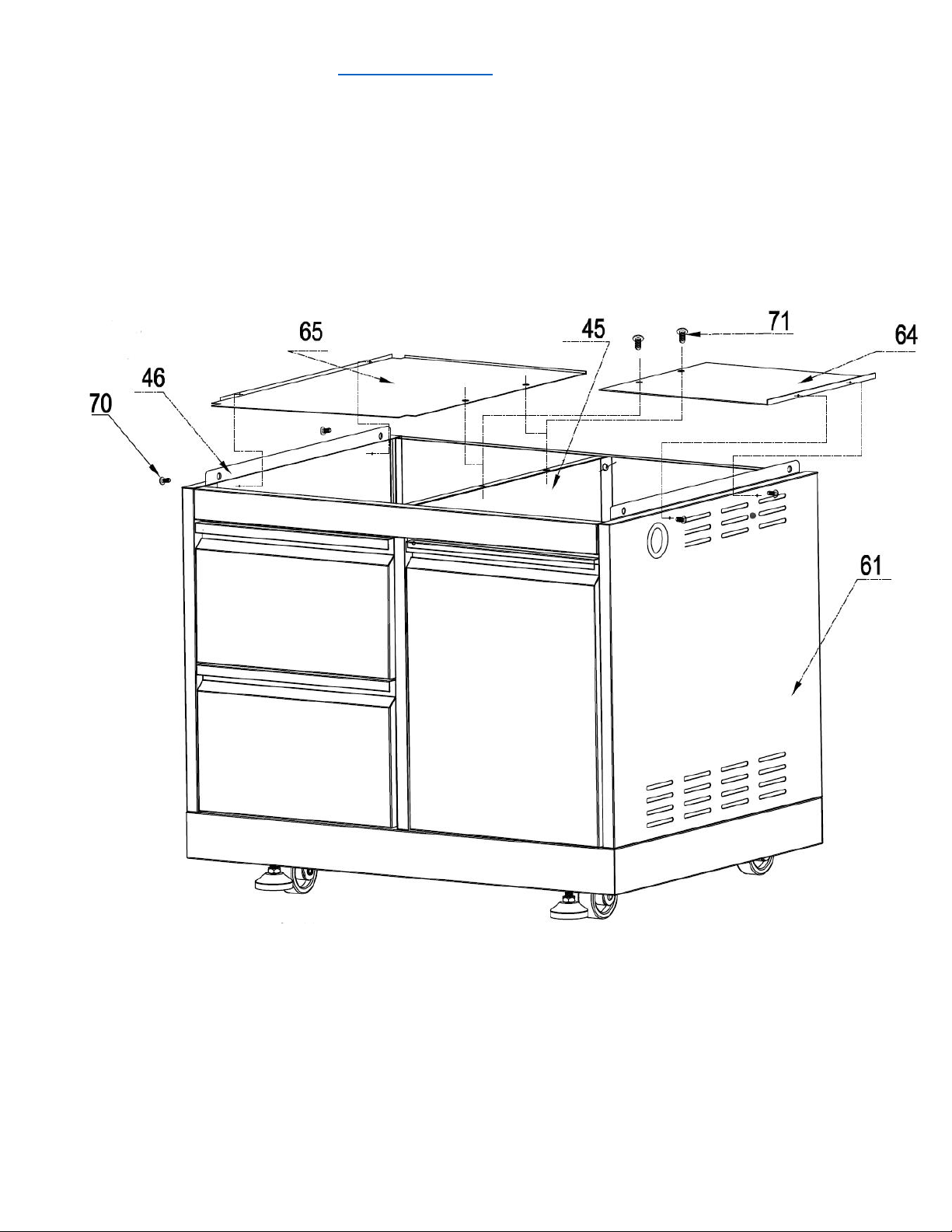
Step. 10
1. Use 2 pcs 5/32" *8 flat head screw (Part # 72) to install laminate board (Part #65) to Left side
panel A welding assembly (Part #46);
2. Use 2 pcs 5/32" *8 flat head screw (Part # 72) to install gas tank heat shield (Part #64) to Right
side panel A welding assembly (Part #61)
3. Use 2 pcs 1/4“*14 Philips thumb head screw with anti-slip design (Part #71) to install Part #64
and Part #65 to Clapboard welding part (Part #45)
service@thorgroup.us +1 877-288-8099
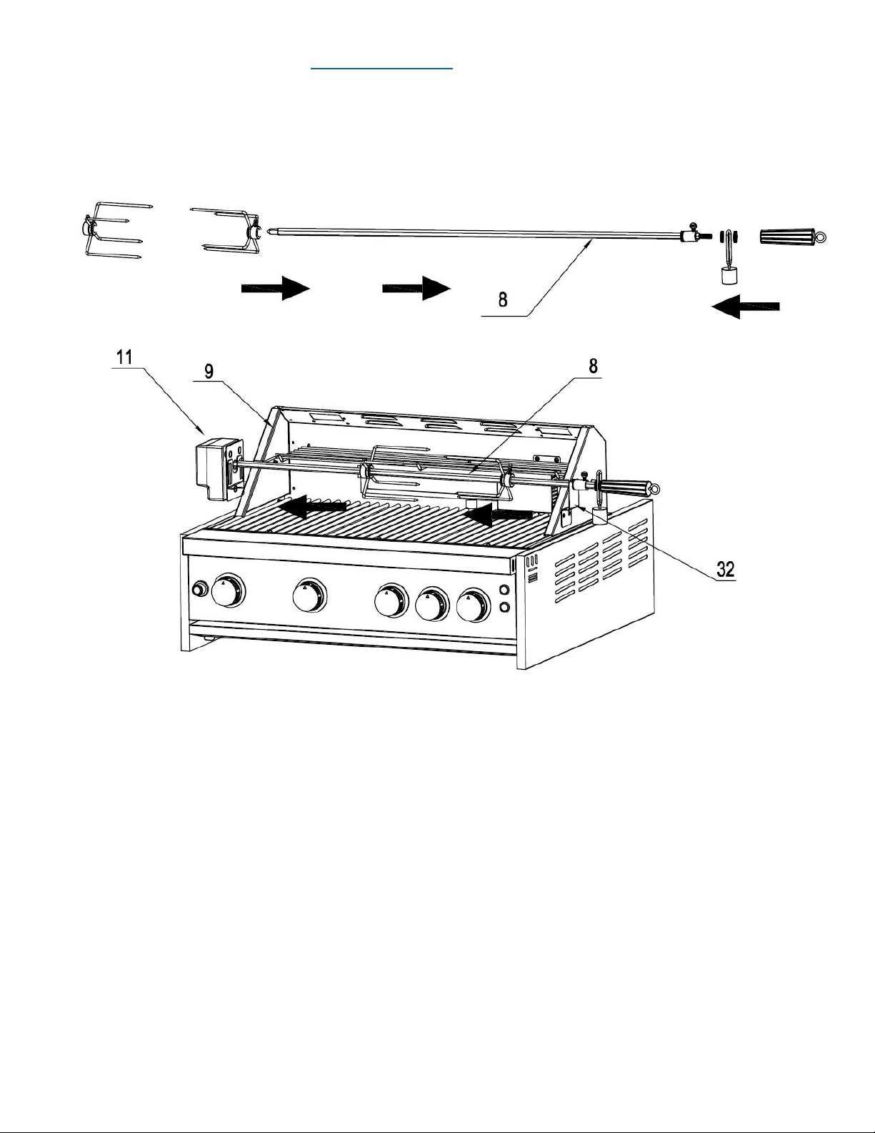
Outdoor Grill Installation
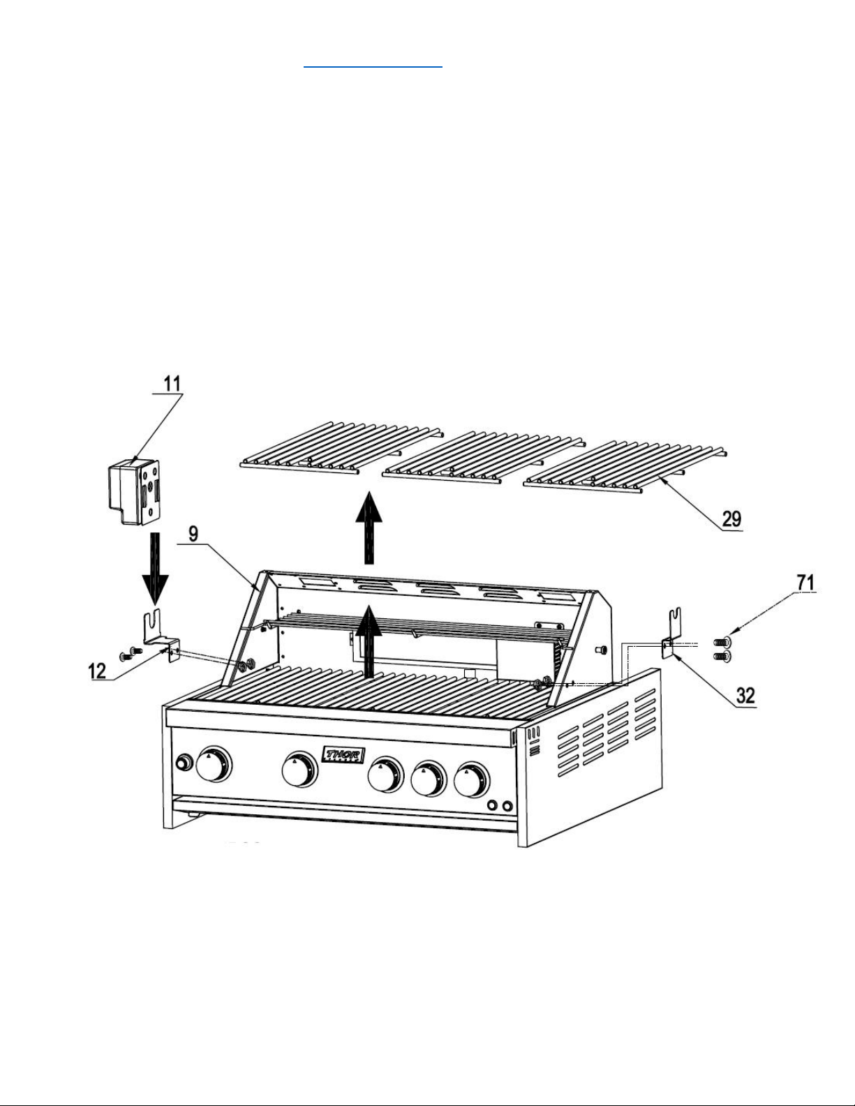
Step 1
1. Open the Grill cover. Remove All 3 pcs cooking racks (Part # 29) for the main burners to avoid
potential damage;
2. Use 2 pcs 1/4“*14 Philips thumb head screw (Part #71) with anti-slip design (Part #71) to install
motor holder (Part #12) to Grill cavity (Part #9);
3. Use 2 pcs 1/4“*14 Philips thumb head screw (Part #71) to install Rotisserie holder (Part #32) to Grill
cavity (Part #9);
4. Put Motor (Part #11) on top of motor support (Part #12) and put back 3 pcs cooking racks (Part #29)