Loading ...
Loading ...
Loading ...
- 16 -
FIG.15
FIG.16
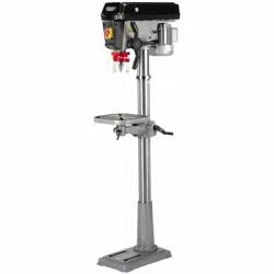
9. SETTING THE DRILL
9.2 DRILL BIT INSTALLATION/
REPLACEMENT - FIG. 15
The drilling machine is equipped with a geared chuck
and a separate key to secure the bit in the chuck
jaws.
Selection of the correct accessory is dependent on
material type and the intended application.
Ensure the selected accessory is suitable and speed
compatible with the drilling machine.
Place the bit into the chuck. Insert the chuck key (X)
into apertures (Y) engaging the teeth.
Rotate the key clockwise to grip. All three apertures
should be tightened to make certain of a firm grip.
Always use a good quality sharp drill bit/cutter.
WARNING: The drill bit will be hot after use.
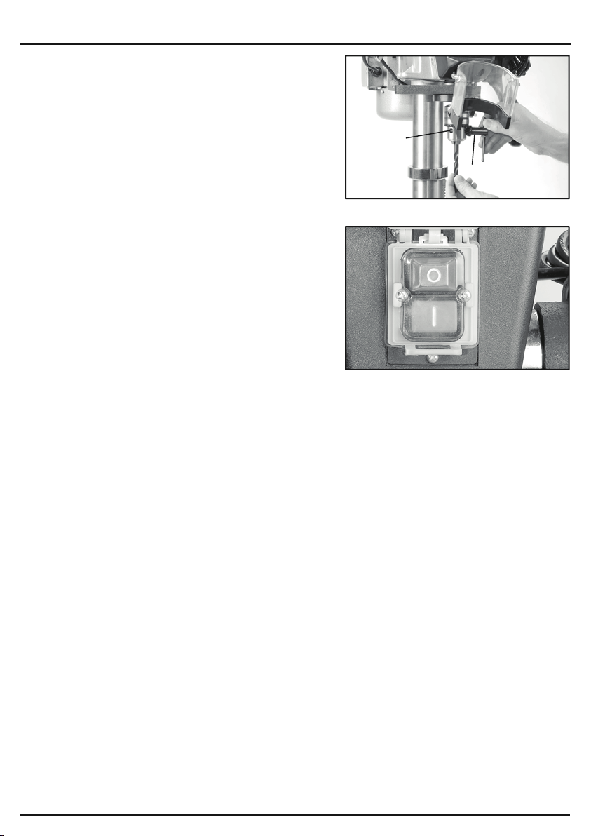
9.3 NO-VOLT SWITCH - FIG. 16
In the event of a power supply disruption the
machine will require manually restarting once
power has been returned.
To switch the machine on, press the green button
marked ‘I’.
To switch the machine off, press the red button
marked ‘O’. However, the yellow cover with integral
red stop button must be left covering the switches
so, in the event of an accident or emergency striking
the stop button will activate the off switch.
Prior to starting the drilling machine make a visual
check, to ensure the guards are in place and
correctly functioning, the bit is correctly installed
with the chuck key removed and no other parts
are damaged proving a potential hazard.
Ensure all locking handles are tight prior to starting
the drilling machine.
(X)
(Y)
FIG.17
FIG.18
9. SETTING THE DRILL
- 17 -
9.4 WORK TABLE ADJUSTMENT -
FIGS. 17 - 18
For versatility, the work table (Z) can be raised or
lowered, tilted ±45° or rotated 360° around the column.
To tilt the table, tighten nut (AA) clockwise until the
locating pin can be removed from the casting. Store in
a safe location. Loosen the 24mm bolt (AB).
Adjust the table’s degree of tilt and re-secure with
locking bolt (AB). Use the scale as a guide.
Alternatively use a protractor off the table to the drill bit
for more accuracy.
When the table is back in a level position insert the
location pin for the factory setting. Move the nut along
the thread until the end of the thread is protected by
the nut, allowing use of a small hammer to tap the pin
in place.
To raise/lower the table working height, loosen locking
handle (AC) and turn the height adjustment crank
handle (AD) to raise or lower the table. Alternatively
while locking handle (AC) is loose the table can be
rotated 180° to further increase the distance between
the chuck and workpiece. When the adjustments are
complete re-secure locking handle (AC).
The slots in the work table and base can
accommodate locking bolts to secure a small vice
enabling safe clamping of the workpiece.
CAUTION: A drill bit snagging on a piece of work will
violently grab the piece of material, whipping it round
and is likely to result in personal injury. Always ensure
the workpiece is securely clamped.
(Z)
(AC)
(AD)
(AB)
(AA)
Loading ...
Loading ...
Loading ...