Loading ...
Loading ...
Loading ...
- 14 -
8. PREPARING THE DRILL
FIG.9
FIG.10
FIG.11
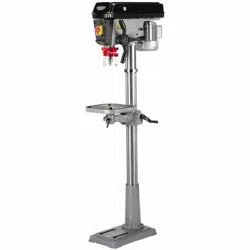
8.6 CHUCK AND ARBOR - FIGS. 9 - 10
The drill chuck, arbor and headstock spindle join
together with an interference fit formed by the matched
tapers of the mating surfaces.
Ensure all mating surfaces are clean as any debris will
cause the taper to miss-align possibly resulting in the
chuck or arbor coming loose creating a potential hazard.
Using the chuck key provided open the chuck until the jaws
are completely recessed and protected from damage.
Insert the short taper end of the arbor (P) into the back
of chuck (Q). A sharp tap with a soft blow mallet will
securely join them together.
NOTE: Ensure the chuck is on a surface that will not
absorb the force of the mallet. If the chuck does not
mate securely, repeat the process.
Insert the long taper end of arbor (P) into the spindle.
Rotate the chuck assembly until the arbor locates
allowing complete insertion.
Tap the chuck to securely locate it in place.
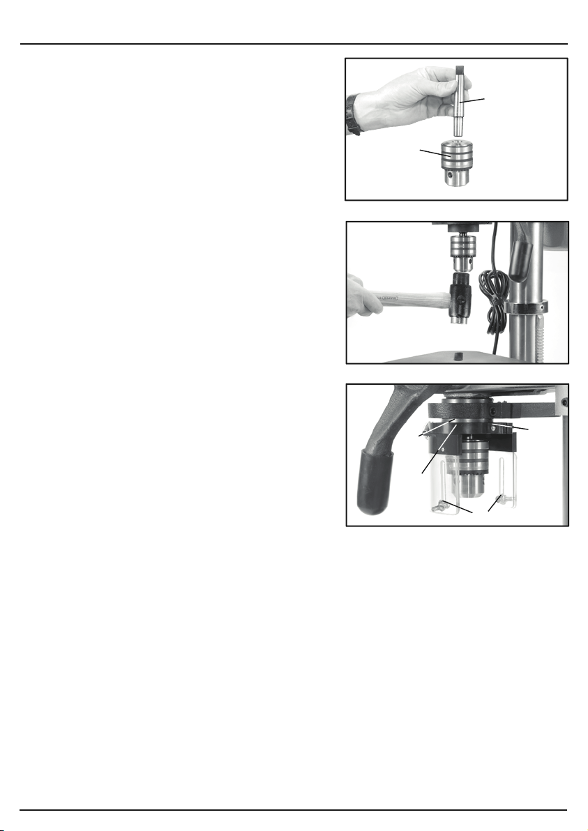
8.7 CHUCK GUARD - FIG. 11
Loosen the cross slot machine screw and nut (R).
Pass the chuck guard (S) over the chuck onto collar
(T). When located fully and aligned on the collar,
tighten the machine screw and nuts to secure the
chuck guard in place.
NOTE: Do not over tighten as it may damage the guard.
To adjust the lower acrylic guard section down and fully
cover the chuck and drill bits, loosen wing nuts (U).
When adjustment is complete, tighten the locking nuts.
NOTE: The chuck guard shall be inspected before
each use to determine effectiveness and correct
functionality.
The chuck guard shall be adjusted and positioned between the chuck and operator for all processes.
Replace a damaged or missing chuck guard before continuing to use the drilling machine.
8.8 BENCH/FLOOR MOUNTING
Securely bolt the drilling machine to a work bench or other secure surface as appropriate through
the various points in the base (fixings are not supplied). Suitable fixings should be sourced
applicable to the load and mounting surface. Ensure there is enough clear space around the
drilling machine to accommodate larger items which may be drilled.
Ensure the load created by the drilling machine, operator and workpiece combined will not
compromise the integrity of the intended mounting surface/floor space.
(P)
(Q)
(U)
(S)
(R)
(T)
9. SETTING THE DRILL
- 15 -
FIG.12
FIG.13FIG.14
NOTE:
Remove the plug from the socket before
carrying out adjustment, servicing or maintenance.
9.1 SPINDLE SPEED ADJUSTMENT
FIGS. 12 - 14
This drilling machine is equipped with 16 drilling speeds.
Remove the pulley cover securing screw.
Select the speed most suitable for the intended
application
†
.
Loosen both the locking knobs (V) and adjust the
motor tension lever (W) releasing the tautness across
the drive belts.
Move the belt to the corresponding sections of the
motor, intermediate and spindle pulleys ensuring the
belts remain horizontal.
Apply pressure to the motor tension lever (W) to
tension the drive belt. With the correct tension
achieved. Tighten both locking knobs (V).
Gently lower the pulley cover before tightening pulley
cover securing screw.
Never attempt to operate the drilling machine with the
pulley cover open or not fully secured.
CAUTION: Over tensioning the drive belt will
accelerate belt wear, increase the loading on drive
bearings and the motor possibly leading to premature
failure. Under tensioning the drive belt will lead to the
drive belt slipping and increased noise.
†
As a general rule material with a softer composition
can be drilled faster as they cut more easily. Harder
materials require a slower speed as attempting to
make the hole at a high speed will result in the drill bit
over heating which may result in a poorly finished hole,
the bit annealing or the bit breaking.
Drilling wood too slowly can cause splintering.
MOTOR
PULLEY
INTERMEDIATE
PULLEY
SPINDLE
PULLEY
A
B
C
D
E
1
2
3
4
1
2
3
4
5
BD650/16E
DP650/16E
Slow
1
Fast
16
Setting
1
2
3
4
5
6
7
8
9
10
11
12
13
14
15
16
Speed
210 min
-1
280 min
-1
320 min
-1
420 min
-1
500 min
-1
540 min
-1
800 min
-1
830 min
-1
1,110 min
-1
1,290 min
-1
1,350 min
-1
1,580 min
-1
2,050 min
-1
2,180 min
-1
2,580 min
-1
3,340 min
-1
Drive Belt Position
Spindle
A - 1
A - 1
B - 2
B - 2
C - 3
A - 1
E - 5
D - 4
E - 5
C - 3
B - 2
D - 4
E - 5
C - 3
D - 4
E - 5
Motor
4 - 4
3 - 3
4 - 4
3 - 3
4 - 4
2 - 2
4 - 4
3 - 3
3 - 3
2 - 2
1 - 1
2 - 2
2 - 2
1 - 1
1 - 1
1 - 1
(V)
(V)
(W)
Loading ...
Loading ...
Loading ...