Loading ...
Loading ...
Loading ...
- 12 -
8. PREPARING THE DRILL
WARNING: The headstock, and consequently when
fully assembled the drilling machine, are extremely
heavy. Care shall be taken when manoeuvring. The
use of a hoist should be employed to ensure safety.
NOTE: Remove the plug from the socket before
carrying out adjustment, servicing or maintenance.
8.1 BASE TO COLUMN - FIG. 1
Align the column (B) onto the base (A) and secure
with the four 16mm bolts (C).
NOTE: Do not overtighten the bolts as this may crack
the casting.
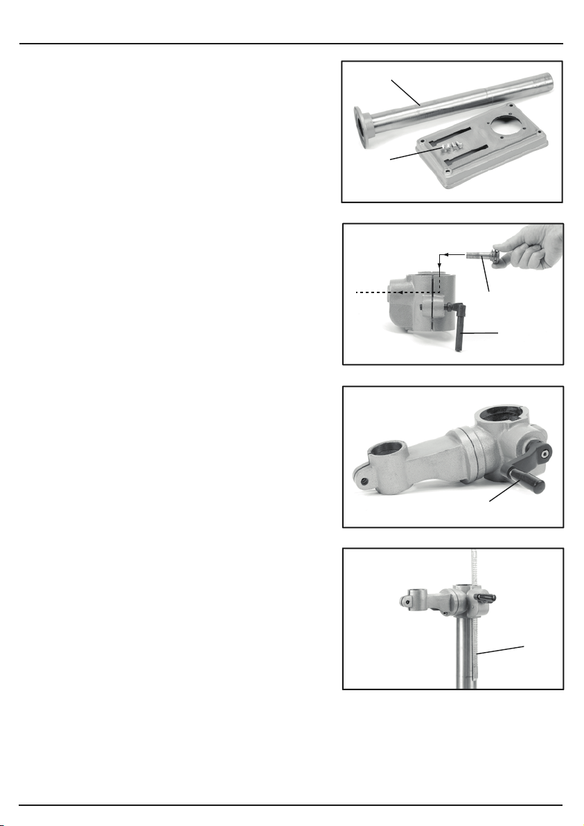
8.2 TABLE BRACKET - FIGS. 2 - 5
Loosely screw locking handle (D) into rear of
the table bracket. Pass the pinion gear (E) inside the
table bracket and pass the shaft out through the
housing side. The pinion gear shaft has one flat side
on which the crank handle (F) secures. Tighten the
locking grub screw with a 3mm hex. key.
NOTE: The toothed rack (G) must be orientated so
the larger non toothed section is upper most.
Position the rack (G) against the column and pass
the table bracket over.
Align the teeth on the rack with those of the worm
gear inside the table arm.
When the gear and rack teeth are intermeshed,
the rack and table arm can be lowered over/down the
column.
NOTE: The rack must be held in position while
lowering to avoid movement.
Locate the bottom end of the rack into the top edge of
the column base. The bevelled edge holds the rack
against the column.
Tighten the table height locking handle.
FIG.1
FIG.2
FIG.3
FIG.4
(C)
(B)
(E)
(F)
8. PREPARING THE DRILL
- 13 -
Slide the column ring (H) over the column and
locate the bevel on the top edge of the rack into
the bevelled rim of the ring. Tighten grub screw
(I) to secure.
NOTE: Adjust the table arm height to suit and
position centrally over the base before securing
the locking handle.
8.5 PLUNGE HANDLES - FIG. 8
Locate the plunge handle assembly (M) onto
the hub ensuring locating pin (N) is in position.
Secure with the hex. socket head bolt and
washer (O).
8.3 TABLE - FIG. 6
Slot the table into the table bracket and tighten
locking handle (J).
8.4 HEADSTOCK - FIG. 7
WARNING: The headstock assembly poses a
significant health and safety hazard while being
lifted and positioned into place. Seek assistance.
Lift the headstock (K) onto the top of the column.
When aligned and located down onto the column
fully, tighten grub screws (L) with the hex. key
supplied.
NOTE: Adjust the drill head over the table and base
before securing. The use of a plumb bob may be
beneficial to improve accuracy.
FIG.5
FIG.6
FIG.7
FIG.8
(I)
(H)
(J)
(L)
(K)
(N)
(O)
(M)
Loading ...
Loading ...
Loading ...