Loading ...
Loading ...
Loading ...
7
ENGLISH
Voltage and Circuit Protection
Refer to the Voltage and Minimum Branch Circuit
Requirements under Specifications.
• Voltage supply to circuit must comply with
the National Electrical Code.
• Circuit is not used to supply any other electrical needs.
NOTE: If compressor is connected to a circuit protected by
fuses, use only time delay fuses. Time delay fuses should be
marked “D” in Canada and “T” in the US.
Main Power Disconnect Switch
Install a main power disconnect switch in the line from the panel
to the compressor. The main power disconnect switch must be
located near the compressor, for ease of use and safety. When
turned OFF, the main power disconnect switch shuts off all power
to the compressor. When it is turned ON, the compressor will start
and stop automatically, controlled by the pressure switch.
Electrical Wiring
WARNING: Improper electrical installation of this
product may void its warranty and your fire insurance.
Have circuit wiring performed by qualified personnel
such as a licensed electrician who is familiar with the
current national electrical code and any prevailing local
electrical codes.
WARNING: Risk of electrical shock. Improper electrical
grounding can result in electrical shock.
The wiring should be done by a qualified electrician.
A qualified electrician needs to know the following before wiring:
• The amperage rating of the electrical box is adequate.
Refer to the Specifications, in the instruction manual, for this
information.
• If the supply line has the same electrical characteristics
(voltage, cycle, phase) as the motor. Refer to the motor
nameplate, on side of motor, for this information.
NOTE: The wiring used must be rated for the motor nameplate
voltage, plus or minus 10%. Refer to local codes for recommend-
ed wire sizes, correct wire size, and maximum wire run.
Undersized wire causes high amp draw and overheating to the
motor.
NOTE: A circuit breaker is recommended. If the air compressor is
connected to a circuit protected by a fuse, use only time delay
fuses.
WARNING: Risk of electrical shock. Electrical wiring
must be located away from hot surfaces such as
manifold assembly, compressor outlet tubes, heads,
or cylinders.
Air Distribution System
WARNING: Risk of bursting. Plastic or PVC pipe is not
designed for use with compressed air. Regardless
of its indicated pressure rating, plastic pipe can
burst from air pressure. Use only metal pipe for air
distribution lines.
INSTALLING AND DISCONNECTING HOSES
WARNING: Risk of unsafe operation. Firmly grasp
hose in hand when installing or disconnecting to
prevent hose whip. Ensure regulated pressure gauge
reads 0 PSI.
The next figure represents a typical air distribution system.
The following are tips to remember when setting up the air
compressor’s air distribution system.
NOTE: Compressed air from oil lubed air compressors will
contain water condensation and oil mist. Several drains, traps
and filters will be needed to supply air without water
(including aerosols) or oil to spray equipment, air tools and
accessories requiring filtered air. Always read the instructions
for the air tools and accessories being used.
• Use pipe that is the same size as the air tank outlet. Piping
that is too small will restrict the flow of air.
• If piping is over 100' (30.5 m) long, use the next larger size.
• Bury underground lines below the frost line and avoid
pockets where condensation can gather and freeze. Apply
pressure before underground lines are covered to make
sure all pipe joints are free of leaks.
• A flexible coupling is recommended to be installed
between the globe valve/air discharge outlet and main air
distribution line to allow for vibration.
• A separate regulator is recommended to control the air
pressure. Air pressure from the tank is usually too high for
individual air driven tools.
• DO NOT install lubricators between the tank and any spray
equipment, air tool or accessory requiring oil-free filtered
air.
• Drain all traps, filters and dirt legs daily.
SEE NEXT PAGE FOR TYPICAL COMPRESSED AIR DISTRIBUTION
SYSTEM
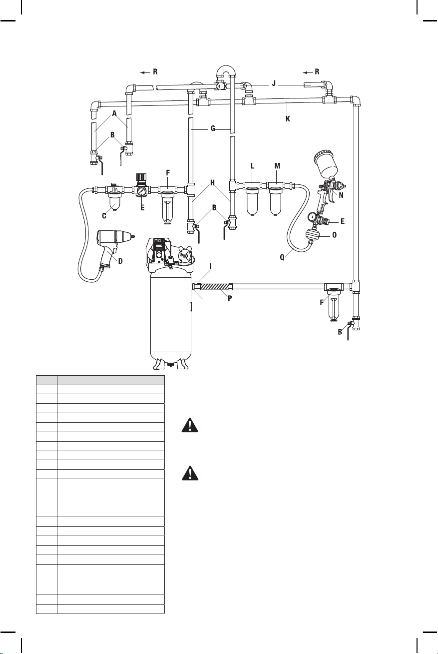
TYPICAL COMPRESSED AIR DISTRIBUTION SYSTEM
ENGLISH
S
Part Description
A
Drain Legs
B
Drain Valves
C
Lubricator
D
Air Tool
E
Regulator
F
Filter / Moisture Trap
G
Air Usage Lines
H
Dirt Legs
I
Air Discharge Valve
J
Feeder Lines Slope with Air Flow
K
Main Distribution Air Lines - Slope pipe in direction
of air flow. Water condensate flows along bottom
of pipe to drain legs, preventing it from entering
feeder lines.
L
5 Micron Filter
M
.01 Micron Filter
N
Spray Gun
O
Ball Fitter
P
Flexible Coupling
Q
For Best Performance - The distance between the
compressor and the moisture trap should be as
long as possi
ble.
R
Air Flow
S
Air Outlet
OPERATION
WARNING: To reduce the risk of serious personal injury, turn
unit off and disconnect it from power source before making
any adjustments or removing/installing attachments or
accessories. An accidental start-up can cause injury.
WARNING: Risk of unsafe operation. Unit cycles
automatically when power is on. When performing
maintenance, you may be exposed to voltage sources,
compressed air, or moving parts. Personal injuries can occur.
Before performing any maintenance or repair, disconnect
power source from the compressor and bleed off all air
pressure.
Loading ...
Loading ...
Loading ...