Loading ...
Loading ...
Loading ...
SERVICE AND
FRONT-TO.:BACK ADJUSTMENT (See Figs. 20 and 2t) _
IMPORTANT; DECK MUST BE LEVEL SIDE-TO-SIDE, IF
THE FOLLOWING FRONT,.TO-BACK ADJUSTMENT iS
NECESSARY. BE SURE TO ADJUST BOTH FRONT LINKS
EQUALLY SO MOWER WILL STAY LEVEL SIDE-TO-SfDE
To obtain the best cutling resuIls, the mower housing
should be adjusted so ]he front is appioximately 1/8" to 1/2"
tower than the rear when the mower is in tls highest
position.
Check adjustment on right side of tractor, Measure dis-
fence _'F' directly in front ol and behind the mandrel at
botlom edge of mower housing as shown
* Before making anynecessaryad_ustments, checkthat
both front links are equal in lenglh
° tf links are not equal in length, adjust one link to same
length as other link
. Tolower front of mower housing. Ioosen nut"G"on both
front links an equal number of turns
• When distance "F" is 1/8" to I/2" lower at front than
ADJUSTMENTS
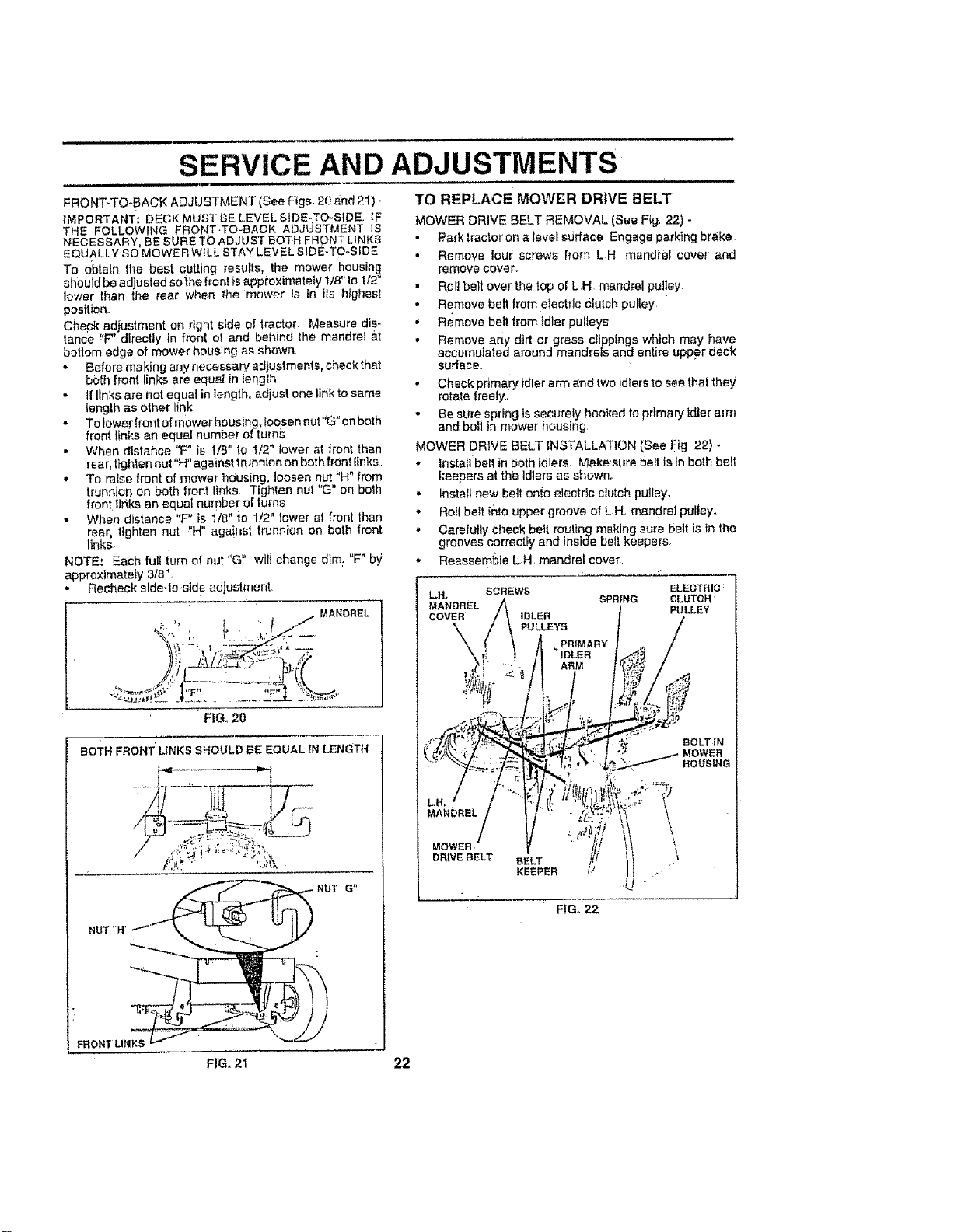
TO REPLACE MOWER DRIVE BELT
MOWER DRIVE BELT REMOVAL (See Fig 22) -
• Park tractor on a level sdrface Engage parking brake
• Remove tour screws from L H mandi'el cover and
remove cover,
• Roll belt over the top of L H mandrel pulley.
• Remove belt from electrlc Clutch puliey
• Remove belt from idler pulleys
• Remove any dirt or grass clippings which may have
accumulated around mandrels and enIire upper deck
sudace.,
" Check primary idler arm and two ldlers to see that they
rotate freely
• Be sure spring is securely hooked to primaryldler arm
and boil in mower housing
MOWER DRIVE BELT INSTALLATION (See Fig 22) -
rear. tighten nut"H" against trunnion on both frOnt links
,, To raise front of mower hdusing loosen nut"H" from
trunnion on both front links Tighten nut 'G on both
front rinks an equal number of turns
• When distance "F" is 1/8" {o 1/2" lower at front than
rear. tighten nut "H" aga!nst trunnion on both front
links-
NOTE.' Each full turn o! nut "G" wilt change dim; "F" by
approxlmateLy 3/8"
° Recheck s_de-to.std e adjustment
. MANDREL
" FIG. 20
BoTH FRONT" LINKS SHOULD BE EQUAL tN LENGTH
,' Install belt in both idlers. Make'sure belt is in both belt
keepers at the idlers as shown.
,, Install new bett onie electric cIutch pulley.
• Roll bett into upper groove of L H. mandrel pulley..
• Carefully cheek betl rou!lng making sure belt is in the
grooves correctly and inside belt keepers.
• Reassembfe L.H, mandrel covet"
ELECTRIC:
CLUTCH
PULLEY
BOLT IN
HOUSING
MANDREL
DRNEBELT BELT
KEEPER tJ
\
\
\
FIG. 22
FRONT LINKS
FIG. 21 22
Loading ...
Loading ...
Loading ...