Loading ...
Loading ...
Loading ...
SERVICE AND ADJUSTMENTS
.,HI., H., ,,J ,,,,H., 11 , ..............................
CAUTION; BEFORE PERFORMING ANY SERVICE OR ADJUSTMENTSi ...............
Depress clutch/brake pedal fully and set parking brake,,
Place motion control lever in neutral (N} position_
Place attachment clutch In "DISENGAGED" positiom
Turn ignition key "OFF" and remove key.
• Make su_e the blades and all moving parts have completely stopped.
• Disconnect sparkplug wire from spark plug and place wire Where it cannot come In contact with
plug,
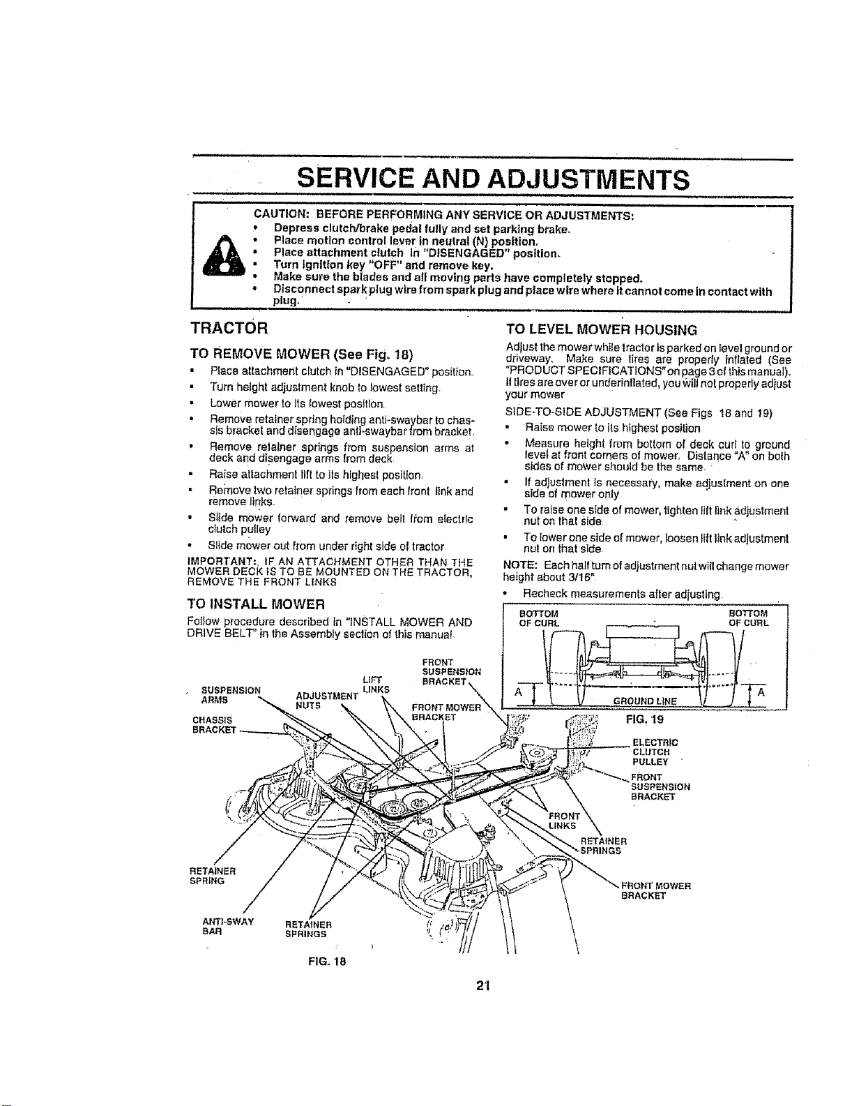
TRACTOR TO LEVEL MowER HOUSING
Adlust the mower white tractor is parked on level ground or
TO REMOVE MOWER (See Fig_18) driveway, Make sure liree are properly inflated (See
• Place attachment clutch in "DISENGAGED" pos[tiOn.r "PRODUCTSPECIFICATIONS"onpage3oIthismanual),
• Turn height adjustment knob fo lowest setting Iltlresareoverorunderinflated, you_viltnoipreperlyad ust
your mower
• Lower mower to Its lowest position siDE-TO-SIDE ADJUSTMENT (See Figs 18 and 19)
• Remove retainer spring holding antJ-swaybar to chas-
Sis bracket and disengage anli-swaybar from bracket • Raise mower to its highest position
, Remove relalner springs from suspension arms at " Measure height from bottom of dec{ cur!, o ground
deck and disengage arms from deck levef at front corners of mower, Distance A on bo{h
• sides of mower should be the same.
• Raise atlachmen! till to its highest position, • If adjustment is necessary, make adjustment on one
• Remove two retainer springs from each front link and side of mower only
remove links.
. To raise one side of mower, tighten lift link adjustment
• Slide mower forward and remove bell !,_om electric nut on that Side
clutch
-"_"pudey • To fewer one side of mower, loosen lift }Inkadjustment
• Slide mower out from under right side el tractor nut on that side
IMPORTANT:, iF AN ATTACHMENT OTHER THAN THE NOTE: Eachhaffturnofadiustmentnutwillchangemower
MOWER DECK IS TO BE MOUNTED ON THE TRACTOR, height about 3/16"
REMOVE THE FRONT LINKS
TO INSTALL MOWER Recheck measurements after adjusting
BOTTOM BOTTOM
FoIIow procedure described in "INSTALL MOWER AND OFCURL t- _, ..1 OFCURL
DR'VE BELT' in the Assembly section of this manua, l(_tf_ _._ _--'-_ /
FHONT /J I_-=,, -_I_l It
LIFT BRACKET_ _ _...... LV_ " -" , -- _'_ tvl .....
SUSPENSION LINKS A
" NUTS FRONTMOWER_,, _' ..............
CHASSIS BRACKET X,,_I'_;; FIG. 19
ELECTRIC
CLUTCH
PULLEY "
FRONT
SUSPENSION
i/ BRACKET
\
RETAINER
SPRING
FIG. 18
FRONT MOWER
BRACKET
21
Loading ...
Loading ...
Loading ...