Loading ...
Loading ...
Loading ...
12
W415-0764 / C / 11.19.13
EN
4.0.2 FACTORY BUILT FIREPLACE
4.1 LOW CLEARANCE FLUE CONNECTOR (1402)
An optional low clearance fl ue connector is available to facilitate hook up into a tight fi tting fi replace. Consult your
local dealer for details.
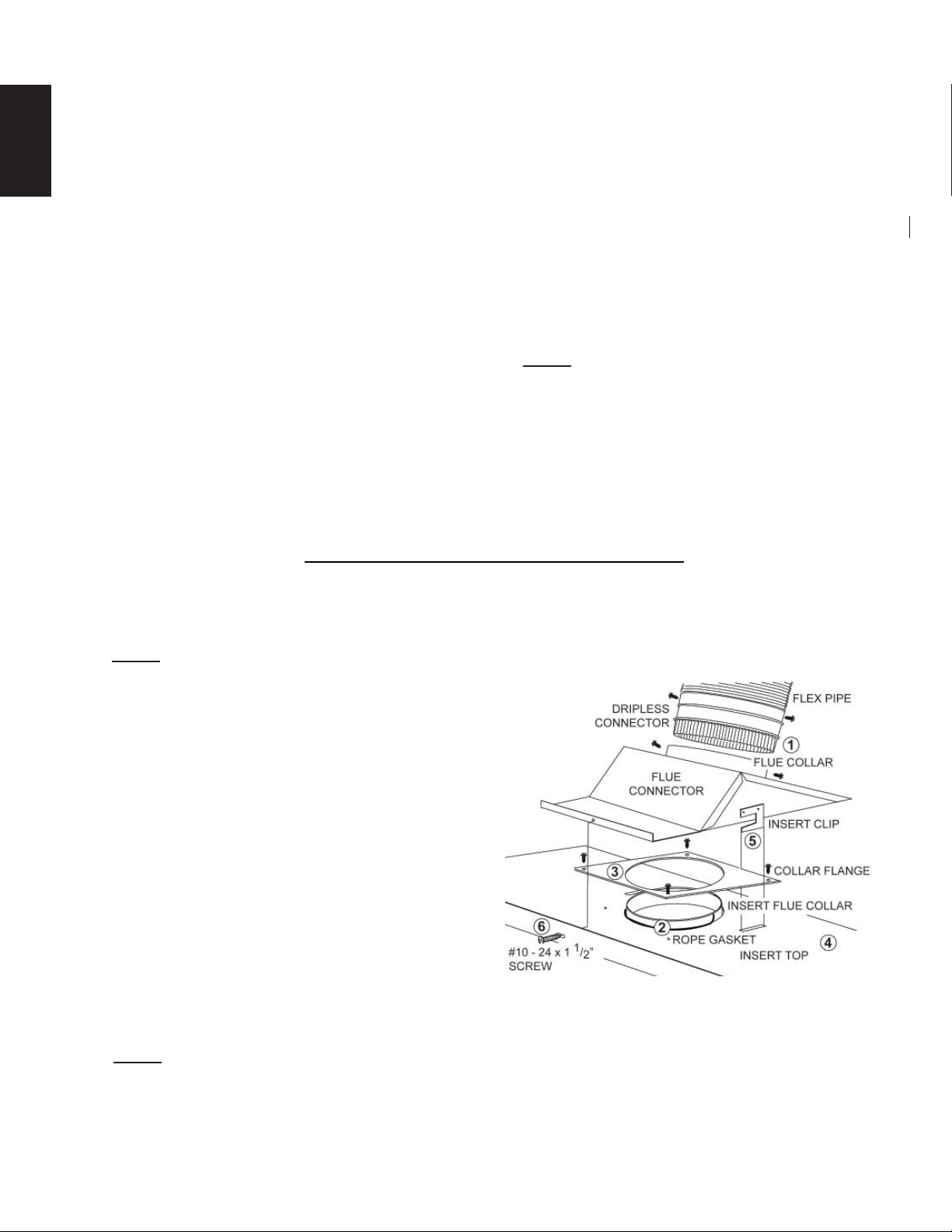
NOTE: This kit should be used in conjunction with a dripless connector between the fl ue collar and fl ex
liner.
4.1.1 Having ensured that the chimney is thoroughly
clean, install the fl ex liner. Insert a dripless con-
nector into the fl ue collar. Attach the fl ex liner to
other end of the adapter. Secure using 6 - #8
screws.
4.1.2-3 Coil the rope gasket around the insert fl ue collar
sealing the gap between the collar and the insert
top. Using 4 - #8 screws, attach the collar fl ange,
squeezing the gasket tightly into place.
4.1.4-5 Move the insert into place in the fi replace. Ma-
neuver the insert clips into the two slots located
on the insert top by reaching through the insert
fl ue collar from inside the insert.
4.1.6 Thread the #10 - 24 screw through the slot located on the insert top and into the threaded hole on the
fl ue connector, allowing the fl ue connector to be drawn forward into place.
NOTE: Check for a good seal between the insert top and the fl ue connector (by holding a fl ashlight up
through the insert collar, etc.).
The following installation requirements must be observed when installing solid fuel burning inserts into factory
built fi replaces.
A. The factory built fi replace must be listed per UL 127 or ULC S610.
B. Clearances to any combustible material surrounding this insert as identifi ed must be followed. These
clearance requirements supersede any pre-existing facing material clearances listed for the factory
built fi replace.
C. Installation must include a full height listed chimney liner meeting HT requirements (2100°F/1149°C)
as required in UL 1777 (U.S.) or ULC S635 (Canada). The liner must be securely attached to the insert
fl ue collar and the chimney top.
D. Means must be provided to prevent room air passage to the chimney cavity of the fi replace. This may
be accomplished by sealing the damper area around the chimney liner, or sealing the appliance front.
E. The air fl ow within and around the appliance shall not be altered by the installation of the insert (i.e.
no louvres or cooling air inlet or outlet ports are blocked), unless specifi cally tested as such for each
factory built fi replace manufacturer and model line. NOTE: Using a louvered face plate (surround)
complies with this requirement.
F. Alteration of the appliance in any manner is not permitted with the following exceptions;
A. External trim pieces which do not affect the operation of the appliance may be removed providing
they can be stored on or within the fi replace for reassembly if the insert is removed.
B. The chimney damper may be removed to install the chimney liner.
G. Circulating air chambers (i.e. in a steel fi replace liner or metal heat circulator) shall not be blocked.
H. Means must be provided for removal of the insert to clean the chimney fl ue.
I. Inserts that project in front of the fi replace must be supplied with appropriate support means.
J. A permanent metal warning label must be attached to the back of the fi replace stating that the fi replace
must be restored to its original condition for safe use without the insert.
80.2B
Loading ...
Loading ...
Loading ...