Loading ...
Loading ...
Loading ...
English 12
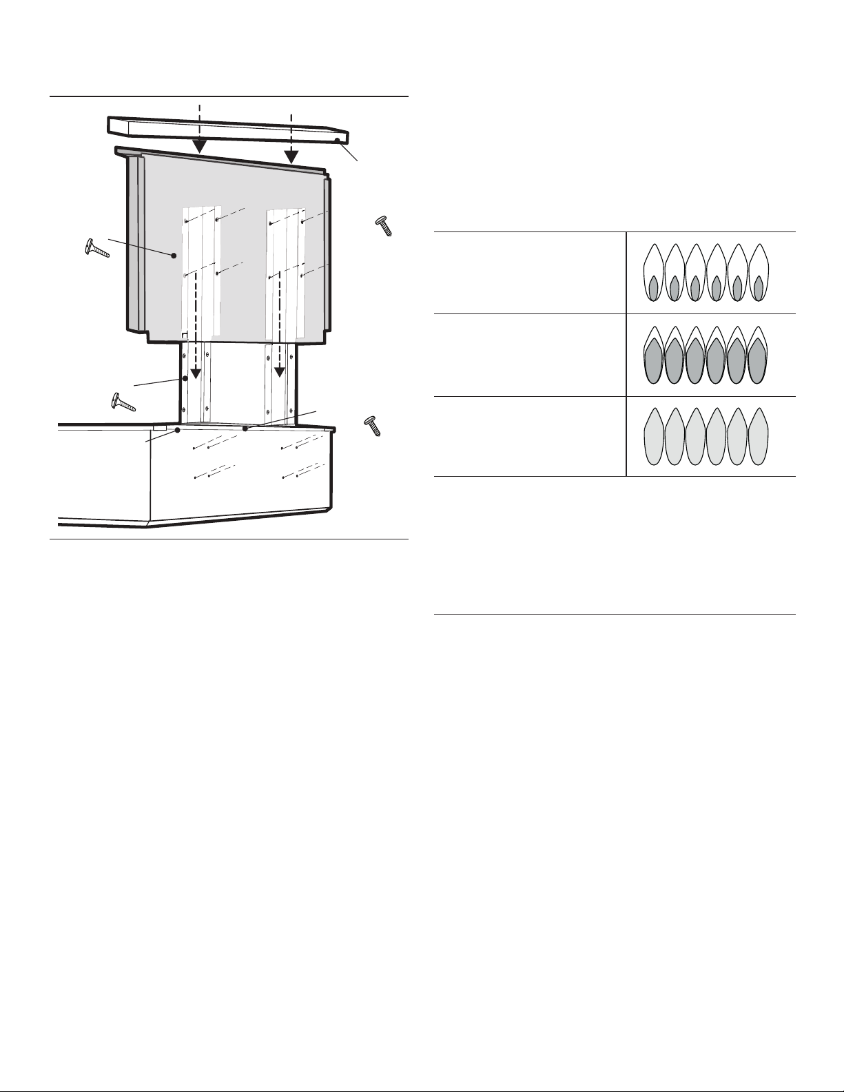
e. Place the backguard cap on top and secure using 2 x
½'' (12.7 mm) stainless screws (E, Figure 12).
Step 7: Burner Test
Test Rangetop Burners
Install any loose components, such as burner caps and
grates that may have been removed earlier. Be certain that
burner caps seat properly into the burner bases. Before
testing operation of the appliance, verify that the unit and
the gas supply have been carefully checked for leaks and
that the unit has been connected to the electrical power
supply. Turn the manual gas shut-off valve to the open
position.
Test Burner Ignition. Select a rangetop burner knob.
Push in and turn counterclockwise to HI. The ignitor/spark
module will produce a clicking sound. Once the air has
been purged from the supply lines, the burner should light
within four (4) seconds.
Test Flame: High Setting. Turn burner on to HI. See
Figure 13 for appropriate flame characteristics. If any of the
rangetop burners continue to burn mostly or completely
yellow, verify that the burner cap is positioned properly on
the burner base, then re-test. If flame characteristics do not
improve, call THERMADOR
®
service.
Test Flame: Low Setting. Turn burner on to LOW. Verify
that the flame completely surrounds the burner. There
should be a flame at each burner port and there should be
no air gap between the flame and the burner. If any burners
do not carry over, call THERMADOR service.
The XLO
®
feature of some of the rangetop burners will
make the flame to cycle on and off when the knob is set to
the XLO range. This is normal operation.
Repeat the Ignition and Flame Test procedures described
above for each rangetop burner.
When flame is properly adjusted:
• There should be a flame at each burner port.
• There should be no air gap between the flame and
burner port.
Call THERMADOR service if:
1. Any of the burners do not light.
2. Any of the burners continue to burn yellow.
Figure 12: Low Back Attachment
c.) Slide backguard
over support brackets
& secure with 8 x
1½" (38 mm) screws
c.) Slide backguard
over support brackets
& secure with 8 x
1½" (38 mm) screws
c.) Slide backguard
over support brackets
& secure with 8 x
1½" (38 mm) screws
e.) Fasten cap
with 2 x ½"
(12.7 mm)
screws
e.) Fasten cap
with 2 x ½"
(12.7 mm)
screws
e.) Fasten cap
with 2 x ½"
(12.7 mm)
screws
d.) Secure front
with ½" (12.7 mm
)
stainless screws
a.) Remove Trim
a.) Remove Trim
a.) Remove Trim
b.) Install support
brackets with 8
x 1½" (38 mm)
screws
b.) Install support
brackets with 8
x 1½" (38 mm)
screws
b.) Install support
brackets with 8
x 1½" (38 mm)
screws
Yellow Flames:
Further Adjustment is
required.
Yellow Tips on Outer
Cones:
Normal for LP Gas
Soft Blue Flames:
Normal for Natural Gas
If the flame is completely or mostly yellow, verify that the
regulator is set for the correct fuel. After adjustment,
retest.
Some orange-colored streaking is normal during the
initial start-up.
Allow unit to operate 4-5 minutes and re-evaluate before
making adjustments.
Figure 13: Flame Characteristics
Loading ...
Loading ...
Loading ...