Loading ...
Loading ...
Loading ...
English 11
• Observe all governing codes and ordinances when
grounding. In the absence of these codes or
ordinances observe National Electrical Code ANSI/
NFPA No. 70 current issue. See Figure 10 for
recommended grounding method.
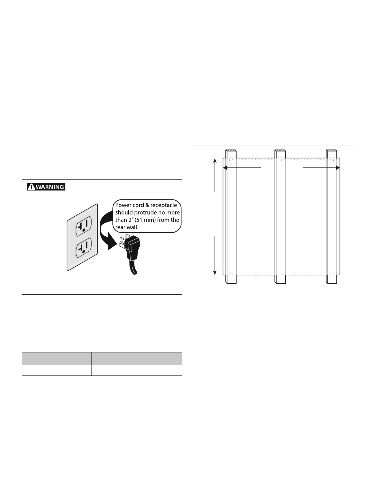
• Power cord and receptacle should protrude no more
than 2'' (51 mm) from the rear wall.
• An electrical wiring diagram and schematic have been
attached to the back of the rangetop chassis for access
by a qualified service technician. Do not remove or
discard this important information.
• Installer - show the owner the location of the circuit
breaker. Mark it for easy reference.
Grounding Method
The rangetop is factory equipped with a power supply cord
with a three-prong grounding plug (with polarized parallel
blades).
Step 6: Backguard Installation
(optional)
Backsplash Installation (PA30JBS)
The Backsplash must be installed prior to installing an
overhead hood given that the hood shell covers the top
mounting screws of the Backsplash.
To protect against scratches, leave protective film on the
Backsplash until after installation is complete.
1. Locate and lightly mark wall studs. Wall studs are
usually installed with a 16'' or 24'' (406 or 610 mm)
space on center.
2. The height of the hood will determine the height of the
top edge of the Backsplash. The Backsplash should be
mounted so that the bottom rear edge of the hood
overlaps the Backsplash 1
½'' (38 mm).
3. Per each wall stud, use two (2) 1'' (25.4 mm) Phillips
head screws to secure both the top and bottom of the
Backsplash (see Figure 11). Space screws evenly
across top and bottom of Backsplash.
• Due to variable wall stud widths and varying
Backsplash widths, in some cases only one wall
stud may be found at the mounting location.
4. Remove protective plastic.
Low Back Installation (PA30GLBC)
Attach the backguard before sliding the appliance into the
final installed position. Follow Steps A through E below:
a. Remove the 2 stainless Torx screws in the front face of
the included Zero Clearance Trim. Lift up to fully
remove the Zero Clearance Trim.
b. Slide the support brackets between the two rangetop
chassis back panels. Secure each bracket with 4 x 1½''
(38 mm) screws (B, Figure 12).
c. Slide backguard over the two brackets on the rear of
the rangetop. Fasten them together with 8 x 1½''
(38 mm) screws (C, Figure 12).
d. Fasten the front of the backguard to the rangetop with
2 or 3 x ½'' (12.7 mm) screws (D, Figure 12).
Figure 10: Recommended Grounding Method
12'' Low Back Backsplash
PA30GLBC PA30JBS
7KLVSURGXFWPXVWEHSURSHUO\JURXQGHG
/05&1MVHTUZMFTNBZWBSZ
Figure 11: Backsplash Installation
42" (1067 mm)
30" (762 mm)
Loading ...
Loading ...
Loading ...