Loading ...
Loading ...
Loading ...
English 9
Step 3: Unpacking and Moving
the Rangetop
1. Verify that the appliance is correct for the type of gas
being provided. Refer to Step 4 before proceeding with
the installation.
2. Remove the outer carton and packing material from the
shipping base. Ensure that you have
all rangetop
components before proceeding.
3. Remove the cooking grates and burner caps
to reduce
rangetop’s weight.
4.
Leave protective film
over brushed-metal surfaces, to
protect finish from scratches, until the rangetop is
installed in its final position.
5. Using a Phillips head screwdriver, remove the three
mounting brackets securing the rangetop to the pallet.
Discard the screws and brackets after removal.
6. Attach the backguard (optional) before sliding the
appliance into the final installed position (see Step 6).
7. Lift and place the rangetop in the countertop opening.
Be careful not to pinch the power cord or gas inlet.
Care should be used not to scratch the countertop.
8. Make sure that the power cord is free and hanging
loose.
9. The rangetop must be level for proper performance.
10. Replace the cooking grates and burner caps. Ensure
that the burner caps are correctly seated on the burner
bases.
Step 4: Gas Requirements and
Hookup
Rangetops are shipped by the factory to operate on natural
gas.They must be converted for use with propane. Verify
the type of gas being used at the installation site matches
the type of gas used by the appliance.
If the location site requires conversion from natural gas to
propane (LP), contact the dealer where the unit was
purchased or contact THERMADOR
®
to purchase a
conversion kit. The field conversion kit for the rangetops in
this series is THERMADOR Model PALPKITHP. Obey all
instructions in this kit for correct conversion of the gas
regulator and settings for the gas valves. Field conversion
must be done by qualified service personnel only.
Natural Gas Requirements:
Inlet Connection: 1/2'' NPT (min. 3/4'' dia. flex line)
Supply Pressure: 6'' min. to 14'' max. water column
(14.9 to 34.9 mb)
Manifold Pressure: 5'' water column (12.5 mb)
Propane Gas Requirements:
Inlet Connection: 1/2'' NPT (min. 3/4'' dia. flex line)
Supply Pressure: 11'' min. to 14'' max. water column
(27.4 mb to 34.9 mb)
Manifold Pressure: 10'' water column (24.9 mb)
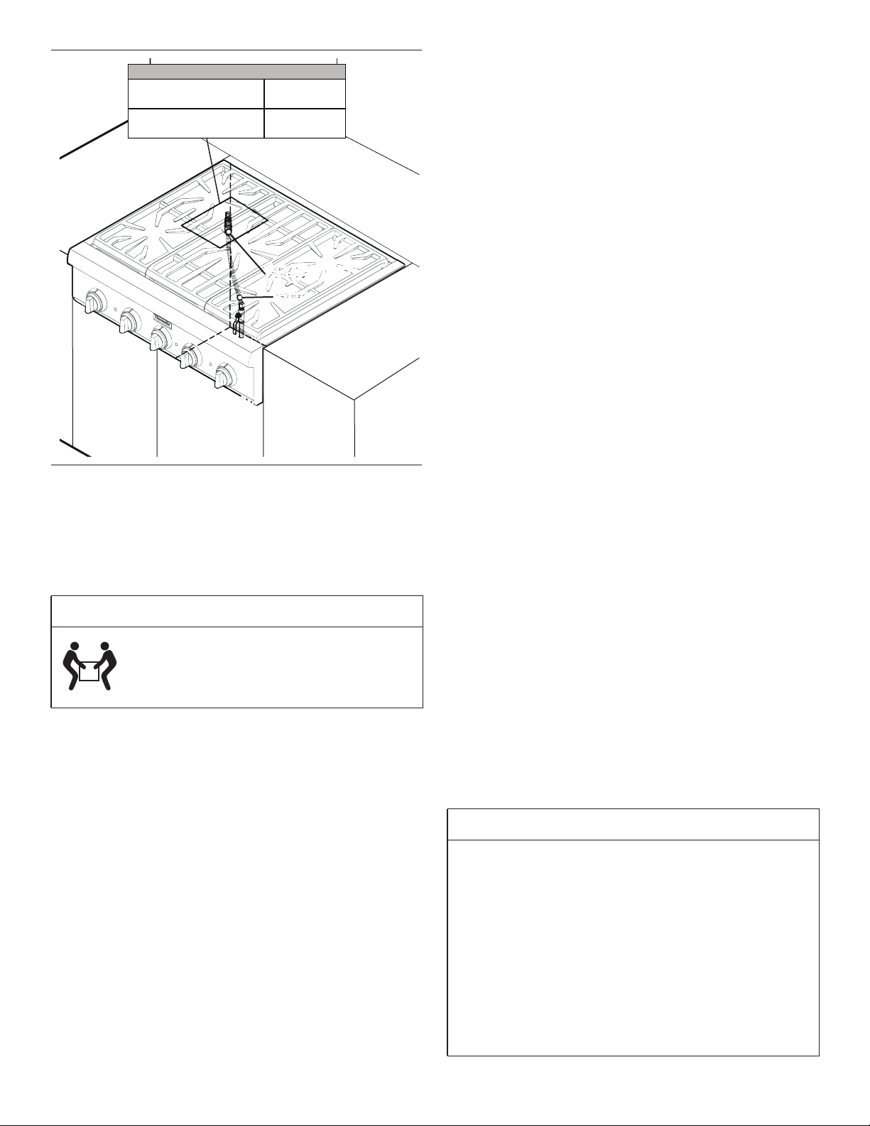
Figure 9: Gas Location
CAUTION
Proper equipment and adequate manpower
must be used in moving the appliance to
avoid damage and/or personal injury. The unit
is heavy and should be handled accordingly.
¾" (19 mm) flex line
¾" (19 mm) flex line
¾" (19 mm) flex line
½" (12.7 mm) NPT
½" (12.7 mm) NPT
½" (12.7 mm) NPT
A manual valve must be installed external
to the appliance, in an accessible location
A manual valve must be installed external
to the appliance, in an accessible location
A manual valve must be installed external
to the appliance, in an accessible location
from the front, for the purpose of shutting
off the
g
as su
pp
l
y
.
from the front, for the purpose of shutting
off the gas supply.
from the front, for the purpose of shutting
off the
g
as su
pp
l
y
.
From left side to
centerline of gas inlet
5⅝" (143 mm)
From rear to centerline
of gas inlet
8½" (215 mm)
GAS INLET LOCATION
WARNING
If a gas conversion kit is used, the kit shall be installed
by a qualified service agency in accordance with the
manufacturer’s instructions and all applicable codes and
requirements of the authority having jurisdiction. If the
information in the instructions is not followed exactly, a
fire, explosion or production of carbon monoxide may
result causing property damage, personal injury or loss
of life. The qualified service agency is responsible for the
proper installation of the kit. The installation is not proper
and complete until the operation of the converted
appliance is checked as specified in the manufacturer’s
instructions supplied with the kit.
Loading ...
Loading ...
Loading ...