Loading ...
Loading ...
Loading ...
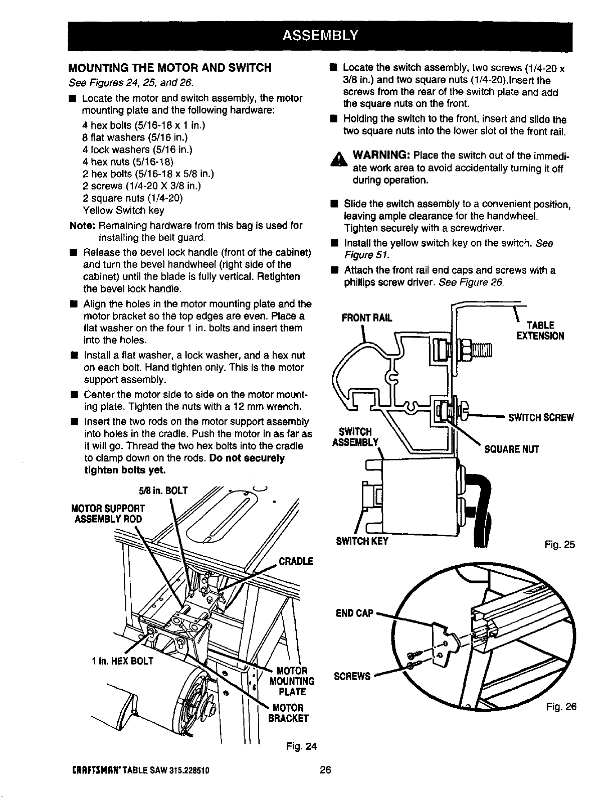
MOUNTING THE MOTOR AND SWITCH
See Figures 24, 25, and 26.
• Locate the motor and switch assembly, the motor
mounting plate and the following hardware:
4 hex bolts (5/16-18 x 1 in.)
8 flat washers (5/16 in.)
4 lock washers (5/16 in.)
4 hex nuts (5/16-18)
2 hex bolts (5/16-18 x 5/8 in.)
2 screws (1/4-20 X 3/8 in.)
2 square nuts (1/4-20)
Yellow Switch key
Note: Remaining hardware from this bag is used for
installing the belt guard.
• Release the bevel lock handle (frontof the cabinet)
and turn the bevel handwheel (right side of the
cabinet) until the blade is fully vertical. Retighten
the bevel lock handle.
• Align the holes in the motor mounting plate and the
motor bracket so the top edges are even. Place a
flat washer on the four 1 in. bolts and insert them
into the holes.
• Install a flat washer, a lock washer, and a hex nut
on each bolt. Hand tighten only. This is the motor
support assembly.
• Center the motor side to side on the motor mount-
ing plate. Tighten the nuts with a 12 mm wrench.
• Insert the two rods on the motor support assembly
into holes in the cradle. Push the motor in as far as
it will go. Thread the two hex bolts into the cradle
to clamp down on the rods. Do not securely
tighten bolts yet.
MOTORSUPPORT
ASSEMBLYROD
lin. HEXBOLT
MOTOR
MOUNTING
PLATE
BRACKET
• Locate the switch assembly, two screws (1/4-20 x
3/8 in.) and two square nuts (1/4-20).Insert the
screws from the rear of the switch plate and add
the square nuts on the front.
• Holding the switch to the front, insert and slide the
two square nuts into the lower slot of the front rail.
,_ WARNING" Place the switch out ofthe immedi-
ate work area to avoid accidentally turning it off
during operation.
• Slide the switch assembly to a convenient position,
leaving ample clearance for the handwheel.
Tighten securely with a screwdriver.
• Install the yellow switch key on the switch. See
Figure 51.
• Attach the front rail end caps and screws with a
phillips screw driver. See Figure 26.
FRONTRAIL
\
TABLE
EXTENSION
SWITCHSCREW
SWITCH
ASSEMBLY
;OUARENUT
SWITCHKEY Fig. 25
ENDCAP
(RRFTSMRN"TABLESAW315.228510
Fig. 24
26
Loading ...
Loading ...
Loading ...