Loading ...
Loading ...
Loading ...
Control locations of the gas surface burners
Your built-in range is equipped with gas surface burners
with different BTU ratings. The ability to heat food quicker
and in larger volumes increases as the burner size
increases.
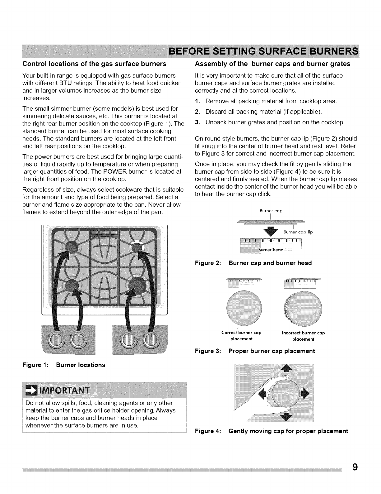
The small simmer burner (some models) is best used for
simmering delicate sauces, etc. This burner is located at
the right rear burner position on the cooktop (Figure 1). The
standard burner can be used for most surface cooking
needs. The standard burners are located at the left front
and left rear positions on the cooktop.
The power burners are best used for bringing large quanti-
ties of liquid rapidly up to temperature or when preparing
larger quantities of food. The POWER burner is located at
the right front position on the cooktop.
Regardless of size, always select cookware that is suitable
for the amount and type of food being prepared. Select a
burner and flame size appropriate to the pan. Never allow
flames to extend beyond the outer edge of the pan.
Assembly of the burner caps and burner grates
It is very important to make sure that all of the surface
burner caps and surface burner grates are installed
correctly and at the correct locations.
1. Remove all packing material from cooktop area.
2. Discard all packing material (if applicable).
3. Unpack burner grates and position on the cooktop.
On round style burners, the burner cap lip (Figure 2) should
fit snug into the center of burner head and rest level. Refer
to Figure 3 for correct and incorrect burner cap placement.
Once in place, you may check the fit by gently sliding the
burner cap from side to side (Figure 4) to be sure it is
centered and firmly seated. When the burner cap lip makes
contact inside the center of the burner head you will be able
to hear the burner cap click.
Burner cap
I
,Burner cap lip
Figure 1: Burner locations
Do not allow spills, food, cleaning agents or any other
material to enter the gas orifice holder opening. Always
keep the burner caps and burner heads in place
whenever the surface burners are in use.
Figure 2: Burner cap and burner head
Correct burner cap Incorrect burner cap
placement placement
Figure 3: Proper burner cap placement
Figure 4:
iiiiiiiiiiiiiiiiiiiiiiiiiiiiiiiiiiiiiiiiiiiiiiiii:iiiiiiiiiiiiiiiiiilii!ii!iiiiiiiiiiiiiiiiiiiiiiiiiiiiiiiiiiiiiiiiiiiiiiiiiiiiiiiiiiiiiiiiiiiiiiiiiiii i ! !! !! !! !! !! !! !! !! !! !! !! !! !! !! !! !! !! !! !! !! !! ! i i i ii ii ii ii ii iiiiiiiiiiiiiiiiiii i i ! ! ! ! ! ! ii iiii i i ii !i i! ii ii ii ii ii ii ii ii ii ii ii ii ii ii ii ii ii ii ii ii ii ii ii ii ii ii i i i i i!i i!i i!
....
Gently moving cap for proper placement
Loading ...
Loading ...
Loading ...