Loading ...
Loading ...
Loading ...
Installation instructions _ l_
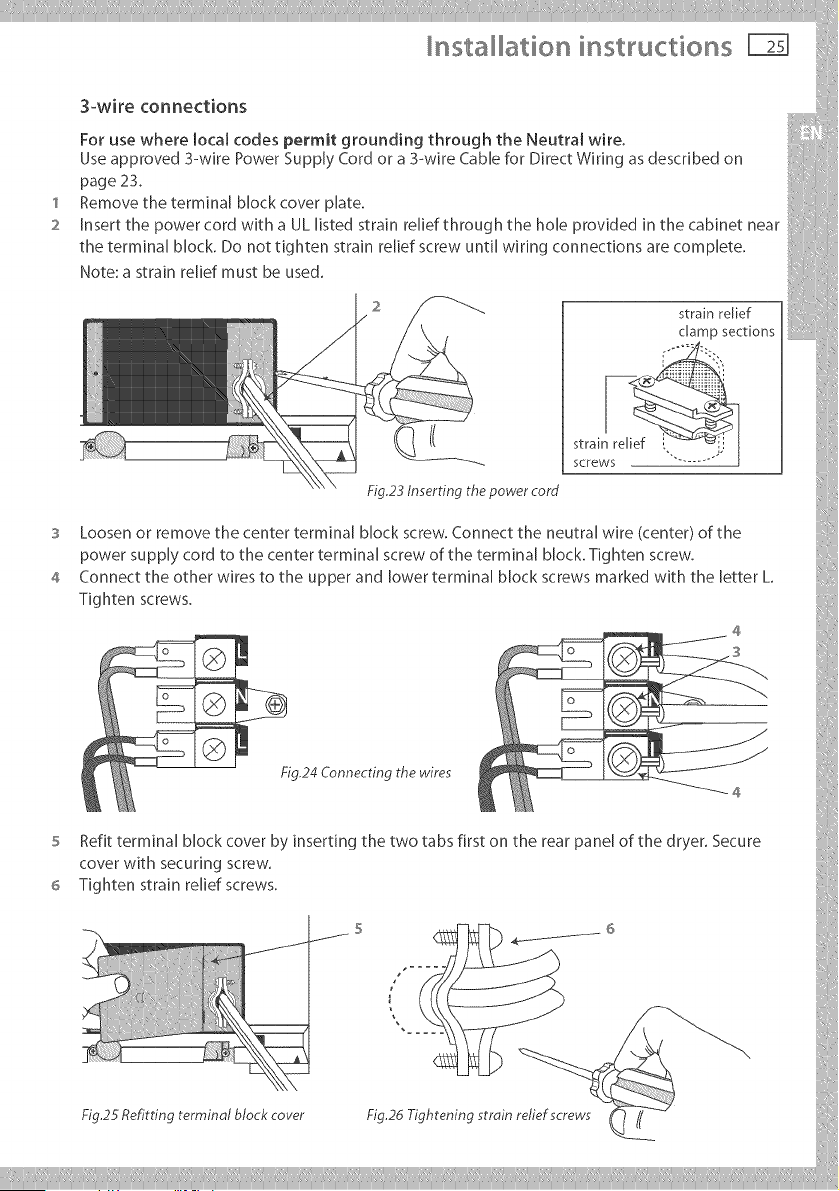
3-wire connections
For use where local codes permit grounding through the Neutral wire. _ :i
Use approved 3-wire Power Supply Cord or a 3-wire CaMe for Direct Wiring as described on
page 23. i
1 Remove the terminal Mock cover plate.
2 Insert the power cord with a UL listed strain relief through the hole provided in the cabinet near
the terminal block, Do not tighten strain relief screw until wiring connections are complete.
Note: a strain relief must be used. i::1
( ' stral
{ )
power supply cord to the center terminal screw of the terminal block. Tighten screw. ::
4 ConnocttheotherwirestotheupperandlowerterminalblockscrewsmarkedwiththeletterL ....
Tighten screws. {:
S Refit terminal block cover by inserting the two tabs first on the rear panel of the dryer. Secure
coverwithsecuringscrew.
6 Tightenstrainreliefscrews.
,..... iii
Fig.25Set!itting terminal block cover Fig.26 Tightening strain relief screws { _ /( )
Loading ...
Loading ...
Loading ...