Loading ...
Loading ...
Loading ...
nsta ation instructions
Fire Hazard
The dryer must be vented to the outdoors.
Use rigid or thick wall flexiMe metal exhaust duct°
Do not use a plastic exhaust duct°
Do not use a meta_ foil exhaust duct°
Failure to follow these instructions can result in death or fire°
The dryer must be exhausted to the outdoors. This w[[[ prevent the build up of lint and moisture
in the room in which it is located and reduce the risk of fire.
This appliance must always be vented to the outdoors.
Exhaust ducting products can be purchased from your local Appliance store or Hardware store.
Plastic or metal foil flexible duct can kink, sag, be punctured, reduce airflow, extend drying
times and affect dryer operation.
A minimum of 4 inch (100 mm) thick wail flexible metal or rigid galvanised metal duct must be
used. Using ducts larger than 4 inches (100 ram) diameter may result in more lint accumulating.
Using straight rigid metal ducting will minimize lint accumulation. Thick wall flexible metal
ducting may be used but care must be exercised to avoid sharp bends which may squash the
duct and cause blockages. Do not use plastic ducting or thin wail flexible metal ducting.
Use duct tape to secure joints. Do not use screws as they collect [int.
Keep ducting as short and straight as possible. Do not exceed the maximum exhaust duct
lengths stated later in these installation instructions.
Do not exhaust the dryer into any other duct, chimney or gas vent, a wail, a ceiling or any
concealed space in a building. Do not exhaust the dryer under a house or mobile home or a
porch, or into a window well or other area that wi[[ accumulate [int.
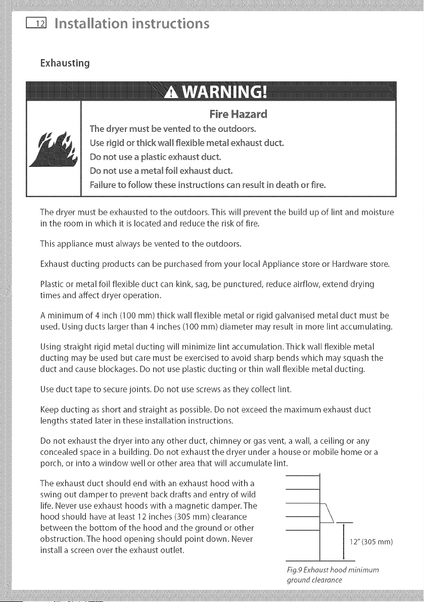
The exhaust duct should end with an exhaust hood with a
swing out damper to prevent back drafts and entry of wild
life. Never use exhaust hoods with a magnetic damper. The
hood should have at least 12 inches (305 ram) clearance
between the bottom of the hood and the ground or other
obstruction. The hood opening should point down. Never
install a screen over the exhaust outlet.
12" (305 mm)
Fig.9Exhousthood minimum
ground cteoronce
Loading ...
Loading ...
Loading ...