Loading ...
Loading ...
Loading ...
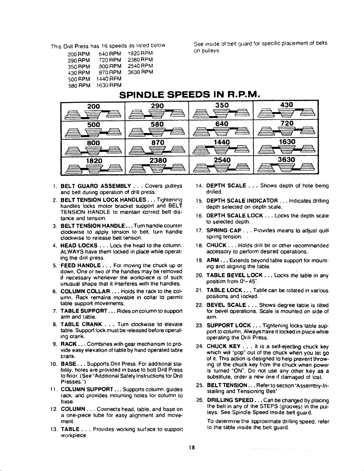
This Drill Press has 16 speeds as hsted Cerow
200RPM 640RPM 1820RPM
290RPM 720RPM 2380RPM
350RPM 800RPM 2540RPM
430RPM 870RPM 3630RPM
500RPM 1440RPM
580RPM 1630RPM
See _nside of belt guard for specific placement of ioelts
on pulleys
SPINDLE SPEEDS IN R.P.M.
, , , ,, , ,,,, i
200
500
8O0
290
1820
580
870
2380
350
640
1440
430
720'
1630
3630
1. BELT GUARD ASSEMBLY . . . Covers pulleys
and belt during operation of drill press.
2. BELT TENSION LOCK HANDLES... Tightening
handles locks motor bracket support and BELT
TENSION HANDLE to maintain correct belt dis-
lance and tension.
3. BELT TENSION HANDLE... Turn handle counter
clockwise to apply tension to belt, turn handle
clockwise to release belt tension.
4. HEAD LOCKS... Lock the head to the column.
ALWAYS have them locked in place while operat-
ing the drill press.
5. "FEED HANDLE... For moving the chuck up or
down, One or two of the handles may be removed
if necessary whenever the workpiece is of such
unusual shape that it interferes with. the handles.
6. COLUMN COLLAR... Holds the rack to the col-
umn. Rack remains movable in collar to permit
table support movements,
7. TABLE SUPPORT... Rides on column tosupport
arm and table.
8. TABLE CRANK . . . Turn clockwise to elevate
table. Support lock must be released before operat-
ing crank.
9. RACK... Combines with gear mechanism to pro-
vide easy elevation of table by hand operated table
crank.
10. BASE... Supports Drill Press. For additional sta-
bility, holes are provided in base to bolt Drill Press
tofloor. (.See "Additional Safety Instructions for Drill
Presses,")
11, COLUMN SUPPORT... Supports column, guides
rack. and provides mounting holes for column to
base.
12. COLUMN... Connects head. table, and base on
a one-piece tube for easy alignment and move-
ment.
13. TABLE... Provides working surface to support
workpiece
14.
15.
16.
17.
18.
19.
20.
21.
22.
23.
24.
25.
26.
DEPTH SCALE... Shows depth of hole being
drilled.
DEPTH SCALE INDICATOR... Indicates drilling
depth selected on depth scale.
DEPTH SCALE LOCK... Locks the depth scale
to selected depth.
SPRING CAP... Provides means to adjust quill
spring tension.
CHUCK... Holds drill bit or other recommended
accessory to perform desired operations.
ARM... Extends beyond table support for mount-
ing and aligning the table.
TABLE BEVEL LOCK... Locks the table in any
position from 0"-45 _.
TABLE LOCK... Table can be rotated in various
positions and locked.
BEVEL SCALE... Shows degree table is tilted
for bevel operations. Scale is mounted on side of
arm.
SUPPORT LOCK... Tightening locks table sup-
port to column. Always have it locked in place while
operating the Drill Press.
CHUCK KEY... It is a self-ejecting chuck key
which will "pop" out of the chuck when you let go
of it. This action is designed to help prevent throw-
ing of the chuck key from the chuck when power
is turned "ON". Do not use any other key as a
substitute, order a new one if damaged of lost.
BELT TENSION... Refer tosection"Assembly-In-
stalling and Tensioning Belt"
DRILLING SPEED... Can be changed by placing
the belt in any of the STEPS (grooves) in the pul-
leys. See Spindle Speed inside belt guard.
To determine the approximate drilling speed, refer
to the table inside the belt guard.
18 .....
Loading ...
Loading ...
Loading ...